C1-C2 Posterior Screw-Rod Fixation
Charbel D. Moussallem
Ahmad Nassr
Bradford L. Currier
Many traumatic, degenerative, inflammatory conditions may result in atlantoaxial instability, which, in certain circumstances, requires surgical stabilization. The C1-C2 joint is highly mobile, has a unique anatomy, and accounts for 50% of the rotation and 10% of the flexion and extension of the cervical spine (25,28), which may predispose this joint to instability. Several techniques have been described to address C1-C2 instability, including wiring techniques, transarticular screw fixation, and rod and screw fixation of C1-C2 (Box 11-1). Surgery for atlantoaxial instability can be challenging because of the unique anatomic and biomechanical considerations of this region. Methods based on C1 lateral mass screws and C2 pedicle or pars interarticularis screws, originally described by Goel and Laheri (12) and popularized by Harms and Melcher (13), have become widely used adjuncts because of their high fusion rates and construct rigidity, which eliminate the need for external halovest immobilization.
The modern technique, described by Harms and Melcher in 2001 (13), uses rods to connect C1 lateral mass screws and C2 screws to stabilize the atlantoaxial joint. This technique is based on the posterior C1-C2 plate and screw construct developed by Goel and Laheri (12) and described in 1994. In their original paper, Harms and Melcher (13) described 37 patients treated by this novel technique. All these patients had solid fusion without any vascular or neurologic complications and without the need for halo immobilization. In this chapter, we describe the indications, contraindications, and surgical steps involved in applying this technique.
INDICATIONS AND CONTRAINDICATIONS
The most common indication for surgery is a displaced odontoid fracture in a patient for whom direct anterior screw fixation is not feasible or is a poor choice. Other indications include less common injury patterns (e.g., displaced fractures of C1, C2, and/or ligamentous instability); inflammatory conditions with resultant instability (e.g., rheumatoid arthritis); congenital or developmental conditions (e.g., symptomatic os odontoideum, Down syndrome, fixed rotatory subluxation) (Fig. 11-1); pathologic lesions with resultant or potential instability; and iatrogenic instability (e.g,, anterior resection of the odontoid).
Surgical stabilization of the C1-C2 joint may also be considered after failure of conservative management of fractures that present with late instability, pain, or myelopathy and in patients in whom external immobilization with a halo-vest is contraindicated.
Contraindications are primarily those related to patient factors and inability to tolerate general anesthesia. In some patients, a severe deformity or erosions caused by inflammatory disorders like rheumatoid arthritis distort the anatomy. Care must be taken when anatomic landmarks for screw fixation are lost. Often, these patients can still undergo the procedure but may require intraoperative navigation to help identify safe avenues for screw passage.
Anatomic variations of the vertebral artery (VA) anatomy may make certain screws dangerous, and careful examination of preoperative images and meticulous planning can avoid a catastrophic vascular injury.
Fractures with severe comminution of the lateral masses of C1 or C2 are also contraindications to the technique.
BOX 11.1 Internal Fixation Methods of the Atlantoaxial Complex
Sublaminar wires, cables, interposition grafting
Interspinous wires, cables, interposition grafting
Clamps, hooks
Transarticular screws
C1 lateral mass with C2 screws (connected by a rod or plate):
Pars interarticularis
Pedicle
Translaminar
Combination of fixation methods
PREOPERATIVE PREPARATION
Imaging
Plain upright radiographs of the cervical spine, including anteroposterior, lateral, and odontoid views, can help the evaluation and surgical plan. In some patients, when instability is not already apparent, lateral flexion and extension views may be helpful to identify dynamic instability. This is not necessary and is potentially dangerous in the acute traumatic patient. A computed tomographic (CT) scan with axial, sagittal, and coronal thin-cut (1 to 2 mm) images is necessary to identify anatomic abnormalities and to help determine the optimal screw length, diameter, entry points, and trajectory. It is ideal to have the CT reconstructed in the plane of the C1 ring for accurate templating. CT angiography can be performed simultaneously to identify the proximity of the internal carotid artery (ICA) to the anterior arch of C1 and to rule out vascular anomalies of the VA (7). CT angiography can help in planning for unicortical versus bicortical C1 screw fixation. Magnetic resonance imaging (MRI) may help define ligamentous injury, the degree of cord compression and myelomalacia, and the space available for supplementary wire fixation. Careful examination of the MRI or magnetic resonance angiography (MRA) can also define the VA anatomy and dominance. Up to 20% of patients may have a VA anomaly (20), and this can be detected on a preoperative CT (or CT angiography) or MRI (or MRA). Another common anomaly is the ponticulus posticus, which can often be detected on the lateral radiograph or CT scan. It is important to recognize this anatomic variant, which is present in 15.5% of patients (32). The presence of ponticulus posticus can give a false sense that the C1 ring is large enough in the cranial-caudal direction to accept a screw placed through the posterior arch of C1 into the lateral mass, resulting in catastrophic VA injury.
Technique
Anesthesia and Monitoring
Awake fiberoptic intubation may be necessary in patients with spinal instability or when the patient does not have adequate mobility of the neck or mouth to allow standard intubation. After induction of general anesthesia, appropriate intravenous access is obtained. Often, an arterial line is placed to monitor blood pressure, which may be necessary in patients with severe myelopathy to maintain adequate cord perfusion pressure. Neuromonitoring with motor and sensory evoked potentials is often used. Prepositioning baseline tracings are obtained, and the tests are repeated after positioning and throughout the procedure. In patients with considerable instability, the head can be secured to the Jackson table with Mayfield pinions or a halo with the patient in the supine position. The patient is then sandwiched between the posterior and anterior portion of the table and then turned to the prone position through the rotating frame. Turning the patient minimizes motion through the cervical spine. Antibiotic prophylaxis should be initiated 30 minutes before incision and then readministered every 3 to 4 hours throughout the procedure.
Positioning
Under general anesthesia, the patient is positioned prone on a Jackson table (or rotated to the prone position as described above), with his or her head fixed with either Mayfield pinions or Gardner-Wells tongs and bivector traction (Figs. 11-2 and 11-3), depending on surgeon preference and the needs of the procedure (26). All bony prominences are carefully padded. The upper extremities are padded and positioned along the sides of the patient’s trunk. The knees should be flexed and well padded. Fluoroscopy is used to check the reduction and alignment of the cervical
spine before preparing the patient. Access to the patient’s head is desirable to allow for manipulation during the procedure to aid in reduction and is one advantage of the bivector traction setup as the head can be manipulated freely.
spine before preparing the patient. Access to the patient’s head is desirable to allow for manipulation during the procedure to aid in reduction and is one advantage of the bivector traction setup as the head can be manipulated freely.
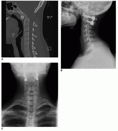 FIGURE 11-1 A: Midsagittal CT scan of the cervical spine showing an os odontoideum that was symptomatic in a young patient. B: Postoperative lateral radiograph showing adequate fusion with a C1-C2 screw-rod construct supplemented by wiring. C: Anteroposterior radiograph of the cervical spine showing the C1-C2 construct. |
Prepping and Draping
The patient’s hair is clipped to a few centimeters above the external occipital protuberance. The skin incision is planned in the midline from just distal to the external occipital protuberance to the level of the C2 spinous process. A chlorhexidine and alcohol solution is used for skin sterilization. An antimicrobial surgical adhesive is used to cover the surgical site as well as sites of possible autograft harvest. We typically include the neck as well as the patient’s trunk in the surgical field to have access to the iliac crests and ribs as potential sites of autologous bone graft. This preparation can also allow for mobilization of a trapezial flap in patients who have had previous radiation or in thin patients when a muscle flap is needed to cover the instrumentation.
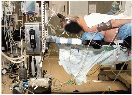 FIGURE 11-2 Positioning of a patient on the operating table in a prone position with bivector traction, with the upper extremities well padded on the sides of the trunk. |
Surgical Exposure
Prior to incision, a solution of 1% lidocaine with 1:100,000 epinephrine is injected into the subcutaneous tissue to help provide hemostasis in patients with good skin vascularity and integrity. A posterior midline incision is made in customary fashion; dissection of the subcutaneous tissue is made by electrocautery to decrease bleeding. The fascia is divided in the midline. Deep dissection is carried out in the midline through the thin white median raphe of the neck to avoid excessive bleeding. Subperiosteal dissection is carried out along the posterior aspect of C1 and C2. Care is taken to avoid injury to the VA along the superior surface of the C1 ring. We try to preserve the attachments of the semispinalis cervicis muscle on the caudal aspect of the C2 spinous process. If detachment is necessary, this can be accomplished by removing the muscle with a small amount of bone for later reattachment to the spinous process (Fig. 11-4). As the exposure is carried laterally, careful subperiosteal dissection should be performed to avoid inadvertent injury to the VA above the ring of C1. Generally, the dissection does not extend further than 1.5 cm laterally on either side. The exact location of the VA can be determined on preoperative MRA or CT angiography.
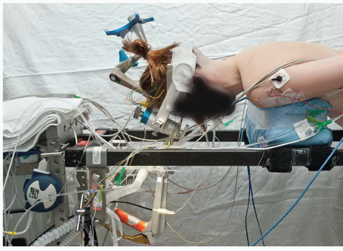 FIGURE 11-3 Positioning of a patient on the operating table with the frame for navigation attached to the Mayfield frame. |
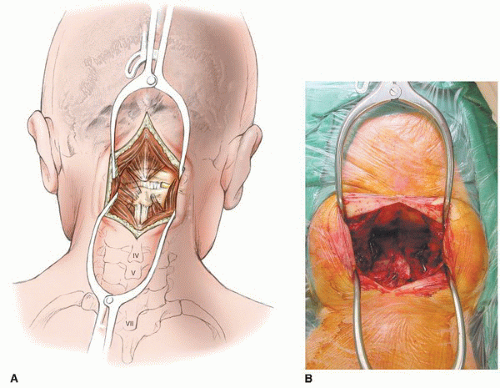 FIGURE 11-4 A,B: Exposure of the atlantoaxial complex after surgical preparation. |
C1 Screw Fixation
Identification of the medial border of the pars interarticularis of C2 locates the entry point of the C1 lateral mass. The medial aspect of the lateral mass of C1 is directly cranial to this point, and this relationship helps determine where to start the dissection caudal to the C1 arch. A Penfield 4 elevator can be used to slide caudal to the arch of C1 just lateral to the location of the C2 pars interarticularis (Fig. 11-5). Hugging the bone of the pedicle analogue of C1, the instrument slides anteriorly until it docks on the posterior aspect of the lateral mass of C1. From here, the Penfield can be slid caudally on the lateral mass to the level of the C1-C2 joint. The second cervical nerve (greater occipital nerve) is retracted caudally with this maneuver. It is often possible to enter the C1-C2 joint through its capsule with the Penfield 4 and thereby maintain retraction of the C2 nerve. Some surgeons elect to sacrifice this nerve (2), but we try to preserve it to avoid postoperative dysesthesia in the distribution of this nerve (16). Surrounding the C2 nerve root and ganglion is a large venous plexus that can bleed easily and obscure the entry point of the screw. Hemostatic agents such as microfibrillar collagen and thrombin or thrombin-soaked sterile compressed sponge (Gelfoam) can be used as necessary. Gentle retraction is key for a safe insertion of the screw. A persistent first segmental artery is a vascular anomaly that is uncommon but presents frequently in patients with bony anomalies. In these patients, the VA is actually caudal to the posterior arch of C1 rather than cranial to it, and it is in the direct path of a lateral mass screw. Preoperative CT angiography or MRA can identify this anomaly and avoid injury to the artery. The venous plexus itself can bleed vigorously and give the impression that a persistent first segmental artery has been injured. Powdered hemostatic agents, a well-placed compressed rayon pad (cottonoid patties), and patience generally take care of the bleeding. In patients with a C1 pedicle analogue (portion of the bone connecting the posterior arch to the lateral mass) large enough to accommodate a screw caudal to the VA, the entry point can be on the posterior arch rather than the lateral mass (5). Care must be taken to ensure the arch is thick enough to avoid injury to the VA in the superior sulcus of C1. The anatomy can often be misleading in patients with a ponticulus posticus (32). Placement of the screw through the posterior arch of C1 can be desirable because it increases the purchase of the screw inside bone, and retracting the C2 nerve and the surrounding venous plexus can be avoided. Unfortunately, placement of this posterior arch screw can be done in only 20% to 40% of patients (5,18


Related posts:


Stay updated, free articles. Join our Telegram channel
Full access? Get Clinical Tree
