Chapter 14 Biomechanics and Vibroarthrography of the Patellofemoral Joint
Biomechanical Functions of the Patella
The patella plays an essential role in transmitting the forces of the extensor mechanism across the knee joint complex. John Sheldon, in 1789, identified this mechanical function, felicitously explaining that “muscles extend the leg by pulling up the Patella, which plays in the groove between the two condyles of the Os Femoris, as a rope in a pulley, and therefore these muscles … act with great mechanical advantage; they not only extend the leg, but assist, likewise, in keeping the thigh-bone fixed upon the Tibia in the erect posture; in balancing the body; and in straightening the knee-joint.”98 However, this message was not accepted universally. In 1937, Brooke concluded that the function of the knee could be improved by performing a patellectomy,9 and the excision as a treatment won many followers.42,113 This treatment protocol was also supported through a number of long-term clinical studies.37,114,119 Tippett further insisted that “one must learn to accept the fact that the patella, like the appendix, is superfluous—a recessive structure.”106 However, more recent research has proven that the knee extension is impaired56 and the peak torque of the quadriceps is significantly reduced after patellectomy. Therefore, preservation of the patella is now being recommended whenever possible.54,59 Moreover, if patellectomy is necessary, reconstructive procedures such as a tibial tuberoplasty are also recommended for consideration.
The articulating portion of the patella is completely covered by hyaline cartilage (4 to 5 mm thick in its central portion), making it the thickest articular cartilage in the body.33 The hyaline cartilage is aneural and therefore well suited for transmitting high compressive forces, several times higher than body weight. The resulting patellofemoral contact stresses are distributed within the thick cartilage, preventing the pain threshold in subchondral bone from being exceeded. These properties, along with the synovial fluid lubrication in the knee joint, allow the patella to transmit considerably high forces in an almost frictionless manner.80
Quadriceps Mechanism Moment Arms
What Is a Moment Arm?
The patella facilitates the extension of the knee by increasing the moment arms of the extensor mechanism forces. To interpret this function correctly, it is necessary to clarify the definition of the moment arm. According to principles of engineering dynamics, the moment of a force is the cross product of a position vector and force vector. This position vector is measured from the reference point to any point on the line of action of the force.58 The force  acting on a particle P shown in Figure 14-1 creates moment
  about the origin of the coordinate system O:
where  is the position vector from the origin O to the particle P. The resulting moment
  will be perpendicular to the plane created by the vectors
  and
and  .
.
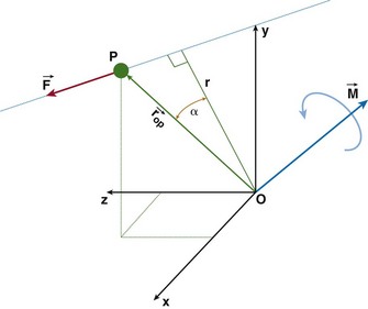
Equation (1) can be rewritten in scalar form as
where r is the moment arm (also called lever arm) of the force  . This equation implies that the magnitude of the moment is equal to the perpendicular distance between the reference point and the line of action of the force, multiplied by the magnitude of that force. Alternatively, we can reformulate this statement and make the following definition of the moment arm: moment arm is the perpendicular (hence, minimum) distance between the reference point and the line of action of the force creating the moment.
It is important to note that the moment arm will depend on the choice of the reference point about which the moment is defined. The choice of the reference point is arbitrary. Engineers use this fact to their advantage and often choose it to be located on the line of action of the force that is unknown or difficult to calculate. By doing this, the moment arm of this force equals zero and the moment of this force is automatically eliminated from the equations of motion. Figure 14-2 shows the schematic, two-dimensional representation of the forces acting on the femoral bone and their moment arms determined with respect to the tibiofemoral contact point (TFCP). The resulting moment equation (applying the convention that moments acting in the clockwise direction are positive, and counterclockwise moments are negative) is as follows:

where d is moment arm, PFJR is the patellofemoral joint reaction, Quad is quadriceps, and W is weight of thigh. Because the tibiofemoral reaction force passes through the TFCP, its moment arm is zero, and this force does not come into the equation. If, for the same system, the reference point was chosen to be at the instantaneous center of rotation (see Fig. 14-2C), the moment equation would be as follows:
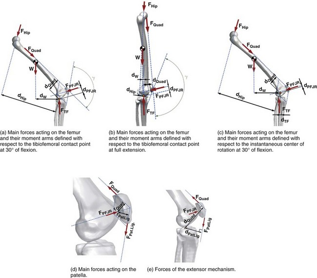
Note that the distances dQuad, dPFJR, dW, and dHip used in equations 3 and 4 are not equal.
Literature Data Discrepancy
The moment arm of the patellar ligament force has been calculated using a number of different reference points, such as the TFCP,* instantaneous center of rotation,59,101,111 intersection of the cruciate ligaments,38,52 or with respect to the instantaneous screw (helical) axis.63 As a consequence, although theoretically all measurements are correct, they differ considerably in magnitude and cannot be accurately compared. Figure 14-3 presents the patellar ligament moment arm calculated in vivo for the same subject using medial and lateral tibiofemoral contact points (see Fig. 14-3A) and the instantaneous center of rotation (see Fig. 14-3B) as reference points. The differences in the moment arm length between the two measurements are shown in Figure 14-3C.
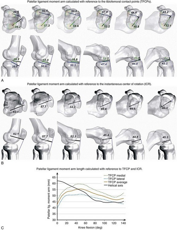
The choice of the instantaneous center of rotation or the screw axis as the reference may be problematic. To find the instantaneous screw axis (ISA) or instantaneous center of rotation (ICR), it is necessary to obtain the relative orientation of the femur and tibia on at least two consecutive instances of motion. Therefore, it cannot be applied to static scenarios. In dynamic scenarios, there may be situations between instances, in which the femur only translates without rotation with respect to tibia. In such case, the center of rotation would be located at infinity and could not be used as a reference. Finally, even in the presence of tibiofemoral rotation, the calculation of the location of the ICR and ISA is prone to error and the accuracy decreases with decreasing intervals between the measurements.78,85,115
The rationale of using the intersection point of the anterior cruciate ligament (ACL) and posterior cruciate ligament (PCL) stems from the classic model of knee kinematics, the crossed four-bar linkage.120 This model assumes that the cruciate ligaments act as ropes and are in tension at all times. Under these assumptions, the crossing point is the point of zero velocity and coincides with the center of rotation. The application of this method under in vivo conditions requires tracking of the two cruciate ligaments, which cannot be done using x-rays or CT scans, but can be located only under static conditions using MRI images. Thus, it may be difficult to use this method effectively under dynamic conditions.
Moment Arms in Natural, Patellectomy, and Total Knee Arthroplasty Knees
In the knee joint, the patella acts as a spacer, increasing the patellar ligament and quadriceps tendon moment arms (see Fig. 14-2E). This mechanical advantage facilitates the process of balancing the moments acting on the knee joint because according to equation 2, for a given moment MO, the increase of moment arm r allows the decrease of the force F.
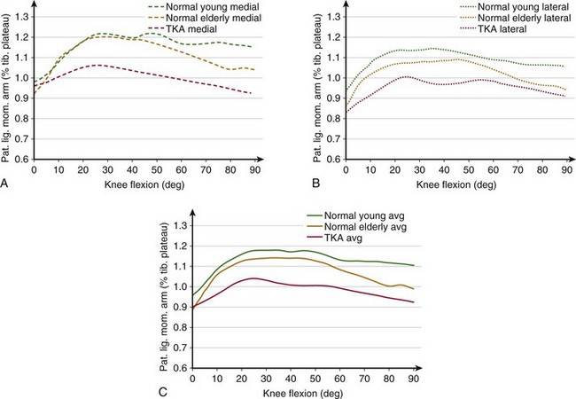
In the first 30 degrees of knee flexion, the patella enters the trochlear groove but is still located anterior to the femur, thus significantly increasing the patellar tendon moment arm (Fig. 14-4). At the same time, the femur rotates externally, the Q angle decreases, and the extensor mechanism becomes aligned in a more straight line, thus reducing the risk of lateral subluxation of the patella. Also, the tibiofemoral contact points move posteriorly because of changes in the geometry of the distal portion of the femoral condyles.31 This posterior motion of the TFCPs significantly increases the moment arms of the patellar ligament and quadriceps tendon. The moment arms remain near their maximum length until approximately 60 degrees, after which the patella begins sinking into the intercondylar groove and its ability to offset the line of action of the extensor mechanism decreases. However, in the healthy joint, the TFCPs continue translating posteriorly until maximum flexion and therefore the moment arms remain larger than at full extension. This compensating effect of posterior translation of TFCPs may be diminished in older and total knee arthroplasty (TKA) patients. TFCPs translate less posteriorly for TKA subjects,22 which may explain the decrease in the patellar ligament moment arm.
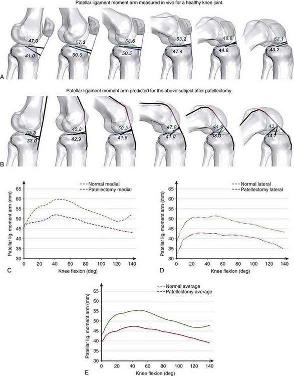
The loss of mechanical advantage of the patella is especially severe for patients undergoing patellectomy. Figure 14-5 shows the patellar ligament moment arm determined in vivo for a healthy individual and the effects of a simulated removal of the patella for the same subject. After patellectomy, the moment arm would be reduced by 14% of the presurgical length (see Fig. 14-5E), which would diminish the performance of the extensor mechanism. Kaufer59 has demonstrated that the extensor mechanism’s power is reduced by 15% after patellectomy and transverse closure and by 30% after patellectomy and longitudinal closure. These adverse effects may explain the inability to extend the knee fully, often observed in patients after patellectomy.
Patellofemoral Kinematics, Tracking, and Contact
Unambiguous Description
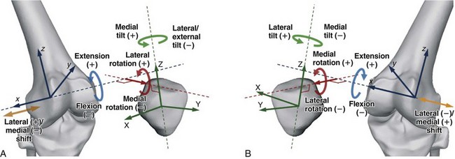
Therefore, in 2002, the Standardization and Terminology Committee of the International Society of Biomechanics (ISB) recommended using the joint coordinate system,117 introduced originally by Grood and Suntay in 1983,41 as the standard for reporting human joint kinematics. Application of this convention offers two main advantages: (1) the rotations remain consistent with clinical terminologies throughout the range of motion; and (2) the rotations are sequentially independent. Bull and colleagues11 have scrutinized the discrepancies among existing systems describing patellofemoral kinematics and have also recommended using the Grood and Suntay convention to describe patellar motion adequately. Therefore, throughout this chapter, their proposed standard will be used, as shown in Figure 14-6.
Patellar Kinematics
Patellar Shift
At full extension, the patella is located above the trochlear groove and may not be in contact with the femur, but it comes quickly into contact when the knee is being flexed. When the patella enters the trochlea, it is located centrally with respect to the groove (Fig. 14-7A). Within the first 30 degrees of knee flexion, the femur rotates externally and the patella either remains centrally or moves slightly medially.49,70 With increasing flexion, it slides distally and into the femoral groove. At this point, the quadriceps is contracting to help balance the knee and the forces exerted by the extensor mechanism pull the patella against the femur. Therefore, the confines of the trochlear groove restrict the patellar medial-lateral translation and “guide” the patella along the trochlea. In vitro studies have shown that after initially remaining centrally, the patella shifts laterally with increasing flexion,14 which was confirmed in vivo using MRI and ultrasound measurements.99 Some of these studies showed that from extension to flexion, this lateral translation may be as large as 1728 or 12 mm,43 but others have reported lower values of 5,81 3,99 and 2 mm.14,79
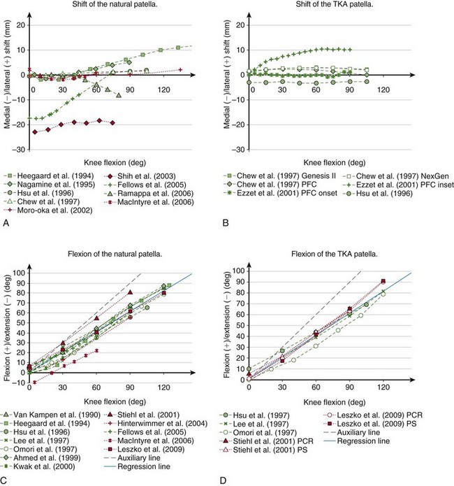
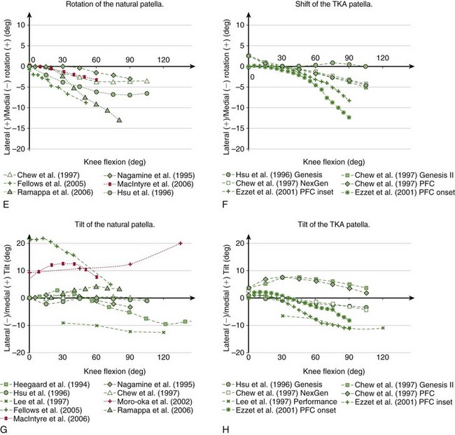
Figure 14-7 Kinematics of the natural (A, C, E, and G) and TKA (B, D, F, and H) patella reported in the literature measured in vitro (green) and in vivo (red). Although according to the chosen convention the flexion of the patella has a negative sign (see Fig. 14-6), it has been plotted as positive to retain the convention predominantly used in the literature.
Chew and associates14 have studied the patellar kinematics of three total knee replacement designs. They found that after the arthroplasty, the patella also translated laterally with increasing flexion, but above 60 degrees it started moving medially (see Fig. 14-7B). However, the range of this secondary medial shift in deeper flexion was small—1.79 mm for Genesis II, 1.55 mm for NexGen, and 2.28 mm for the press fit condylar (PFC) Sigma TKA. Onlay patella buttons were used for all three TKA designs, therefore the differences in kinematics may be attributed to the differences in geometry of the femoral components. However, the amount of the medial-lateral translation may also be influenced by the type of the patellar button. Ezzet and coworkers26 also used the PFC Sigma TKA with an onset patellar button and found approximately 1 mm of medial-lateral translation, similar to the results from Chew and colleagues, but when the inset patellar component was used, the patella translated 10 mm laterally (see Fig. 14-7B).
Patellar Flexion
Patellar flexion increases with increasing knee flexion. This relationship has been consistently observed in vitro* as well as in vivo.48,68,70,104 The patella flexes at a lower rate than the femur relative to the tibia (compare the gray solid line with the dashed line in Fig. 14-7C). The relationship between patellar and tibiofemoral flexion is almost linear; the regression line fitted to the data shown in Figure 14-7C yields the following equation (r2 = 0.96):

The flexion of the implanted patella also increases with knee flexion (see Fig. 14-7D), similar to that observed for the natural patella and can also be approximated by a linear function (r2 = 0.97):

Patellar Rotation
On average, the patella rotates medially with increasing flexion (see Fig. 14-7E).32,49 Fellows and colleagues28 observed an almost linear increase of patellar rotation of 8 degrees from full knee extension to 50 degrees of flexion. Ramappa and associates90 also reported an almost linear increase of 12 degrees between 20 and 80 degrees of knee flexion. Nagamine and coworkers81 and Chew and colleagues,14 however, found a nonlinear relationship of patellar rotation with femoral flexion with considerably smaller ranges—3 and 4 degrees, respectively. MacIntyre and associates70 have observed a general trend of the patella rotating medially with increasing flexion, but noted high intersubject variability in the population of 60 patients evaluated in vivo using MRI.
Chew and coworkers14 found an almost linear change of patellar rotation for three TKA systems. Their results showed that the implanted patella is rotated 2.5 degrees laterally at full extension but rotated 7 degrees medially with increasing flexion (see Fig. 14-7F). Ezzet and colleagues26 found even more medial rotation of TKA patella—8 degrees for the inset and 12 degrees for the onset patella. Their results, however, revealed that the resurfaced patella rotates most after 30 degrees of knee flexion.
Related posts:
 Articular Cartilage: Biology, Biomechanics, and Healing Response
Advanced Technologies in Performing Total Knee Arthroplasty: Roundtable Discussion
In Vivo Mechanics and Vibration of the Knee Joint
Secondary, Spontaneous, and Postarthroscopy Osteonecrosis of the Knee: Diagnosis and Management
Advances in Mechanical Compression Devices
Articular Cartilage Injury and Adult OCD: Treatment Options and Decision Making
Articular Cartilage: Biology, Biomechanics, and Healing Response
Advanced Technologies in Performing Total Knee Arthroplasty: Roundtable Discussion
In Vivo Mechanics and Vibration of the Knee Joint
Secondary, Spontaneous, and Postarthroscopy Osteonecrosis of the Knee: Diagnosis and Management
Advances in Mechanical Compression Devices
Articular Cartilage Injury and Adult OCD: Treatment Options and Decision Making
Stay updated, free articles. Join our Telegram channel

Full access? Get Clinical Tree


