Arthroscopy of the Ankle and Foot


Arthroscopy of the Ankle and Foot


Jeffrey C. Christensen

Meagan M. Jennings

John J. Stienstra


Arthroscopy of the ankle and small joints of the foot is a useful tool in the armamentarium of the foot and ankle surgeon. As with most technologic devices, a unique skill set is required to use the instrument and its accessories. The obvious advantage in arthroscopy, over traditional arthrotomy, lies in its limited dissection and disruption of the soft tissue envelope to accomplish the goals of operation. This sets the stage for reduced postoperative recovery, pain, and swelling compared with traditional open arthrotomy. Although the morbidity of arthrotomy is clearly minimized with arthroscopic technique, if similar surgical objectives are met, frequently, the long-term outcomes of arthroscopic technique parallel those of traditional open technique. In settings in which there is significant surgical pathology and surgical manipulation of the joint structures, such as osteochondral defects, this is especially true. Although it is not always as apparent as with other operations, surgical technique factors into arthroscopic surgical outcomes. It has been observed that “a technically well performed procedure through arthrotomy is preferable to a poorly performed arthroscopic procedure” (1).

The most unique requirement of the necessary skills is the ability to process a two-dimensional image to the three-dimensional anatomy at hand. An additional requirement is that this activity needs to occur without simultaneously looking at one’s hands. In contrast to open surgery, in which the eyes of the surgeon usually visualize the hands of the surgeon, in arthroscopic surgery, the eyes of the surgeon are usually fixed on a monitor and the hands are removed from the operative field. The surgeon’s indirect visualization of the operative field demands interpreting significant variations in magnification and alterations in visual orientation, which make objective perspective a learned skill. Additionally, the technique requires the surgeon to have indirect tactile interaction coupled with managing multiple variables (distension, manipulation, ingress-egress, control of multiple angles of attack and orientation), all capable of causing failure of the procedure, and all in real time.

Owing to the complex interrelationship of this set of variables, arthroscopy has a significant learning curve and is therefore frustrating to many surgeons (2). Most arthroscopic surgeons regard the ankle joint and other joints of the foot as being technically difficult joints to access and perform arthroscopically guided procedures. The skill set necessary to perform arthroscopy can only be acquired in a “handson” setting with one experienced in the technique (3). The authors strongly encourage serious arthroscopic training to begin with a hands-on arthroscopic course that had a dry model and a wet lab component. This chapter makes the assumption that the reader has basic knowledge regarding operative arthroscopy of the foot and ankle. The reader otherwise is referred to previously written works on the basics of the subject (3,4).


HISTORICAL PERSPECTIVE

The history of arthroscopy is quite interesting and has been well covered in previous publications (5,6 and 7). In 1931, Burman developed an arthroscope and surveyed several joints in a cadaver study. He included the ankle as a potential joint for arthroscopy. After testing three cadaver specimens, he concluded that the joint space was too narrow for arthroscopy (8). Clinical success and popularity came with the revolution of endoscope design (9). The podiatric development of the arthroscope in foot and ankle surgery owes much to John Buckholz, Harold Vogler, Richard Lundeen, David Gurvis, and Leonard Janis, all visionaries in foot and ankle arthroscopy. Although Buckholz and Vogler were the first podiatric surgeons to survey the arthroscopic potential in the ankle, Lundeen and Gurvis brought surgical technique to the podiatric profession, organizing the first instructional course in arthroscopy presented to the podiatric profession in 1984 (10).


ARTHROSCOPIC INSTRUMENTATION

The arthroscope is essentially a telescope contained within a cannula that both protects the instrument and allows for controlled fluid flow (ingress or egress). Arthroscopes carry peripherally orientated fiberoptic bundles to illuminate the interior of the joint. These bundles are coupled with a rodlens system to carry reflected light images from the joint to the camera. The size of the arthroscope varies from smaller than 1.5 mm to as large as 7.3 mm outside diameter. The outside diameter of the cannula on a 4-mm scope varies to 5.5 mm. The space between the scope and its cannula has a purpose and allows for ingress (or less commonly egress) of fluid to the joint. The amount of fluid ingress is a function of fluid pressure and sheath size.

The relative diameter of the arthroscope is important because it affects the ease of insertion and movement in a small joint, but more importantly, it also significantly determines the functions of the scope: insufflation, illumination, and image transmission. The ability of the instrument to house light-carrying glass bundles, optical glass, and space for fluid transmission is determined by its cross-sectional area (πr2). The reader should note that an exponential relationship exists between the diameter and the area available for functions of the scope. A 4-mm arthroscope has more than double the crosssectional area and capacity of a 2.7-mm arthroscope. The significant reduction in the capacity for fluid insufflation with the smaller diameter scope can be mediated by adding additional fluid from another cannula. The available light and optical surface area are not as easily compensated for. For these reasons and the relative fragility of small arthroscopes, the most commonly used arthroscopes for the ankle and subtalar joints are
the 2.7-mm and the 4-mm wide angles. In the great toe joint and other tarsal joints, the 2- to 2.7-mm systems are the most appropriate.


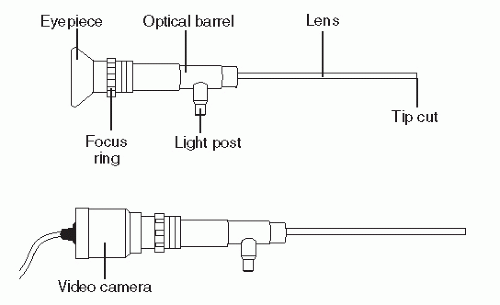
Figure 53.1 The anatomy of the arthroscope.

An adequate light source is critical to success of an arthroscopic procedure. Typically, most systems employ controlled light generated from a halogen or metal halide light source carried to the joint cavity by fiberoptic glass bundles attached to the arthroscope. Most systems employ automatic light intensity controls and a white balance feature to optimize the video image.

The tip of the scope is usually angled from the long axis of the instrument to allow for improved field of view and to allow view around corners. Common tip cut angles are 30 and 70 degrees (Figs. 53.1,53.2 and 53.3). Although there is some variability, the orientation of the tip cut is usually opposite that of the light post. The field of view of the scope is also variable between manufacturers. Improvements in optics have allowed wideangle view, facilitating small joint visualization. Some newer cameras will convert the optical image received to a digitally compressed image for higher resolution.

Most arthroscopy employs high-resolution video systems (camera and monitor) to allow the surgeon to visualize the optical field indirectly. This method of visualization has significantly improved the ease of viewing of the surgical field and secondarily facilitated recording (11).


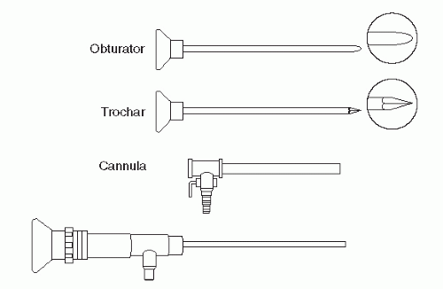
Figure 53.2 Instruments used to introduce the arthroscope into the joint.


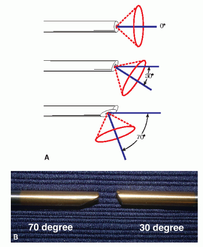
Figure 53.3 A: Effect of tip cut of various types of arthroscopes. B: Close-up comparison of 30- and 70-degree tip cuts.


HAND INSTRUMENTS

A large variety of instruments have been developed for arthroscopy. Those instruments suited for ankle and subtalar arthroscopy generally have outside diameters smaller than 5 mm. Those that are useful in the other joints of the foot are usually smaller than 3 mm in diameter. Available nonmotorized hand instruments include various probes, knives, graspers, and punches (Fig. 53.4). Aspirated motorized instruments (cutters, shavers, and abraders) have made a large impact on the surgeon’s ability to cut, remove, and manipulate because under many circumstances, they are more efficient (Fig. 53.5).


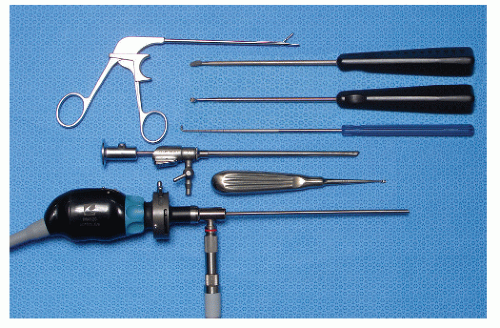
Figure 53.4 Appearance of a typical Mayo stand setup for foot and ankle arthroscopy.


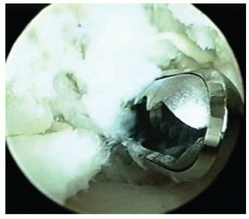
Figure 53.5 A 3.5-mm motorized arthroscopic shaver.


THERMOABLATIVE TOOLS

Other tools available to the arthroscopic surgeon include arthroscopic radiofrequency wands and to a lesser extent Holmium-YAG laser systems that can vaporize, shrink, coagulate, and even weld tissue. Although arthroscopic laser technology has been available for more than 15 years, it remains as controversial as it is expensive, requires special training, and remains unproven with regard to the benefits that may be obtained (12). The radiofrequency wand technology has advanced significantly in recent years to effectively manage soft tissue pathology, especially in a “cleanup” role after the bulk of the soft tissue has been removed. Instrument tips vary in size to adapt to small- and medium-sized joints. Proper fluid management is important to regulate intra-articular temperature with these devices; this is combined with surgeoncontrolled power adjustments to match tissue density and response to thermoablation. Some radiofrequency wands are now aspirated to allow for suction application to assist with fluid flow management and to draw tissue into the wand tip (Fig. 53.6).


TOPOGRAPHIC AND ARTHROSCOPIC ANATOMY


TOPOGRAPHIC ANATOMY

A solid foundation in topographical anatomy is most critical in accurately placing portals. Topographical overlay images are provided to highlight anatomic structures that pertain to common portals (Fig. 53.7). Location of these structures is necessary not only to avoid critical damage but also for proper special positioning to accomplish the surgical goals and access as much of the joint space as possible. In cases involving access of the posterior ankle from an anterior approach, the portal position if placed too high, will make it impossible to access the lesion.

Knowing the predicted nerve tracts relative to possible portal placement helps avoid inadvertent nerve injury, which is the most common complication. In anterior ankle arthroscopy, the anterior lateral portal can often be close to the intermediate dorsocutaneous nerve (IDCN). By plantarflexing the foot and the fourth toe, traction can be applied to the IDCN and often the nerve tract can be visualized in some patients (Fig. 53.8). Nevertheless, use of sound technique in portal development is essential in cases in which there is anatomic variation of nerves and vessels that cannot be anticipated.

In subtalar joint arthroscopy, the most important topographical structure is the floor of the sinus tarsi (see Fig. 53.7B). The entire surgery is keyed off this location. This is critical for accurate portal placement. The course of the sural nerve is important to understand in situations in which middle portal placement or large bore needles are placed to facilitate removal of air or outflow of fluid.


ARTHROSCOPIC ANATOMY

The ankle joint is divided into two distinct zones: that space between the capsule and the osteocartilaginous surfaces, termed the capsular reflection, and that space located directly between the articular structures of the talus, fibula, and tibia. The capsular reflection contains significant space, facilitating the arthroscope and arthroscopic instrumentation. The space between the tibial plafond and the talar dome is generally minimal. This space requires distraction or strategic manipulation to access this zone (Fig. 53.9).


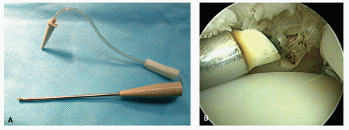
Figure 53.6 A: Example of a bipolar radiofrequency wand. Note 50-degree angle at tip and aspirated system. B: Bipolar wand being used to ablate anterolateral impingement.


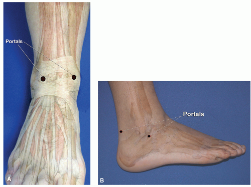
Figure 53.7 A: Topographical anatomy pertaining to portal placement for anterior ankle arthroscopy. B: Topographical anatomy for subtalar arthroscopy.


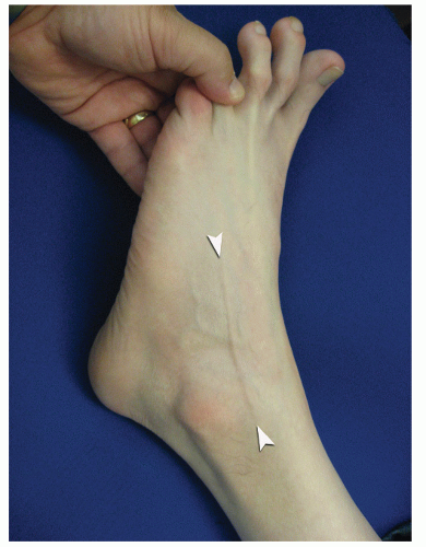
Figure 53.8 Passive plantarflexion of foot and fourth toe causing bow stringing (between arrowheads) of the IDCN.


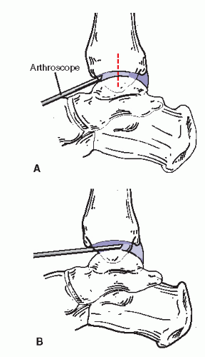
Figure 53.9 Diagram illustrating arthroscope access across the talar dome in undistracted joint (A) and distracted joint (B). Note how the scope orientation changes as it passes posterior.


The joint capsule and pericapsular ligaments define the capsular recesses of the ankle. This capsule is lined with synovial and subsynovial (supporting) tissue that is mainly loose connective tissue containing a network of vascular and lymphatic channels that maintain the intensely well-vascularized synovial bed. Pathologic changes of the synovial and capsular structures are often identified by hyperplasia and injection and with chronic stimulation by metaplasia to dense, space-occupying fibrous tissue. Depending on the situation, intra-articular spaces may be occupied by this pathologic tissue.

The normal capsular recess of the ankle is larger anteriorly than posteriorly. The anterior capsular reflection is divided into anterior, lateral, and medial gutters. The anterior gutter is the space directly dorsal to the talar neck and anterior to the tibial surface. The anterior gutter is used to gain initial entry into the ankle joint. The cartilaginous frontier of the talus rims a plateau that rests above the talar neck just distally. The dorsal talar neck is often viewable without synovial resection. More frequently, the anterior gutter contains proliferative synovium of varying intensity. Portions of the deep deltoid, anterior talofibular, and the distal fascicle of the anterior tibiofibular ligaments can be visualized when entering the ankle arthroscopically (Fig. 53.10).

The posterior capsular reflection of the ankle has minimal volume. It is composed of thick fibrous labrum of the posterior tibiofibular ligament, the transverse ligament, and a similar capsular wall. In most patients, this feature limits mobility of the arthroscope and surgical instrumentation. In close juxtaposition to the posterior ankle pouch is the capsular reflection of the posterior facet of the subtalar joint.


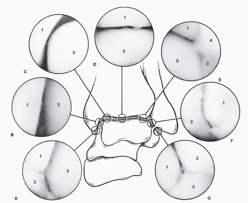
Figure 53.10 Normal arthroscopic intra-articular anatomy of the anterior aspect of the ankle. A: Deltoid ligament and inferior aspect medial malleolus, talus (1, tip of medial malleolus; 2, talus; 3, deltoid ligament). B: Talar medial malleolar joint (1, medial malleolus; 2, talus). C: Medial shoulder to talotibial joint (1, tibia; 2, medial shoulder of talus). D: Tibiotalar joint (1, tibia; 2, talus). E: Tibiofibular-talar articulation (1, tibial; 2, fibula; 3, lateral shoulder of talus; 4, tibiofibular synovial fringe). F: Talofibular joint (1, lateral malleolus; 2, talus). G: Anterior talofibular ligament and inferior aspect of lateral malleolus, talus (1, talus; 2, tip of lateral malleolus; 3, anterior talofibular ligament).


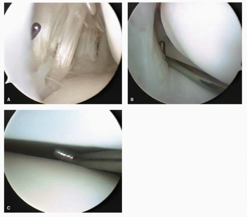
Figure 53.11 Arthroscopic images of the normal subtalar joint anatomy. A: Anterior capsule and retinacular elements of sinus tarsi. B: Interosseous ligament. C: Posterior facet.

In the subtalar joint, the posterior capsular reflection of the posterior facet is large and easily accessed from a posterolateral approach located lateral to the Achilles tendon. The anterior portion of the posterior facet is less amply endowed with space, yet it is easily navigated by the floor of the sinus tarsi and the firm nature of the interosseous talocalcaneal ligament, which marks the deep anterior frontier of the joint. The lateral gutter of the subtalar joint is accessible and is deep to the tip of the fibula, calcaneofibular ligament, and peroneal tendons. The instrumentation can run along the calcaneal side of the subtalar join posterior facet. When traversing the lateral gutter, it is possible to observe the posterior facet and the “saddle” centrally (Fig. 53.11). The posterior talofibular ligament can be visualized going parallel to the posterior half of the posterior facet and terminating at the posterior process. The posterior tibial joint is typically well visualized from lateral to medial to the flexor hallucis longus tendon sheath.

The great toe joint capsular reflection is present in significant variance of volume on the dorsal aspect of the joint. Degenerative changes associated with hallux limitus and hallux valgus frequently obscure the capsular reflection.


ARTHROSCOPIC FUNDAMENTALS


POSITIONING

Individual techniques in the application of arthroscopic technology may vary by surgeon, but ultimately, the basics remain the same. For ankle arthroscopy, the patient is typically placed supine, with the knee either straight or bent over a knee stirrup or over the end of the table. The author’s preference is to place the knee straight, unless the noninvasive ankle distractor is used, in which case the knee and hip are flexed. Some surgeons prefer the patient supine, with the knee flexed over the end of the table, the surgeon sitting directly in front of the dependent leg and ankle. For subtalar joint arthroscopy, a lateral recumbent position facilitates access to the sinus tarsi and the posterior ankle and foot. A prone position maybe desirable for situation of more involved posterior joint pathology (13,14). These situations may require the use of both the posterior lateral and medial portals.

Some authors recommend the use of an arthroscopic leg holder. This accessory device may be helpful in some cases in
which additional leg stabilization or leg elevation off the operating table surface is necessary (Fig. 53.12). However, in the vast majority of cases, simple padding, straps, and sand bags offer sufficient positioning assistance and immobilization.


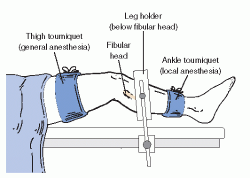
Figure 53.12 Illustration of one type of positioning and support of the leg with tourniquet positioning options.


HEMOSTASIS

Tourniquet or pharmacologic hemostasis during arthroscopic surgery of the foot and ankle is not mandatory. The pressure of distension is usually adequate to maintain a blood-free field. In those cases in which bleeding is excessive, a small quantity of epinephrine added to the ingress fluid is often sufficient to control small vessel hemorrhage. A tourniquet placed either at the thigh or proximal to the ankle is a safe method for managing bleeding when it is excessive or when epinephrine is either ineffective or contraindicated (Fig. 53.12). The use of thermoablative wands toward the end of the procedure can facilitate a more rapid cleanup and also help manage bleeding from soft tissues.

At the completion of the operative portion of the procedure, the surgical site is assessed for hemostasis. When there is any question of vascular injury associated with portal development, the tourniquet is released before application of the bandage for inspection and potential ligation of any bleeding vessels. In some situations in which significant intra-articular bleeding is noted, an active, closed suction drain is easily placed through the portal into the joint.


JOINT DISTENSION AND FLUIDS

Once the patient is anesthetized and a sterile field has been created, the ankle joint is distended with fluid. This is usually done before portal development to permit maximal distension of the capsule. The accuracy of portal orientation is enhanced by tactile feel of the needle traversing the proposed path of the arthroscope. Because they are fundamental to joint visualization, distension and maintenance of distension are two of the most important principles of joint arthroscopy. Usually, lactated Ringer or normal saline are used because they are readily available. Questions have been raised as to which fluid is best for performing arthroscopy. Of common fluids available to the surgeon, lactated Ringer is more physiologic than normal saline in all models (15,16 and 17). While there are solutions that may be more physiologic to cartilage cells in the laboratory setting, there is no evidence that more expensive solutions are clinically justified.

Distension is maintained by balancing the ingress and egress of fluid from the joint. Gravity drainage or active pumps are used to deliver fluid, usually through the cannula of the arthroscope. When using a small-diameter arthroscopic cannula, distension is often supplemented from a separate ingress cannula. Drainage of fluid from the ankle joint is through cannulas and more commonly along the surface of the instruments inserted in the portal. Maintenance of appropriate distension pressure is sometimes a complex and changing problem, requiring the surgeon’s attention as the case progresses (18). The surgeon and the assistants should regularly take note of the periarticular soft tissues to observe for potential fluid accumulation in the fascial planes about the ankle. Although there are no reports of significant morbidity from this situation in the ankle, it is usually avoidable and should be corrected, if possible. Compartment syndrome as a result of fluid extravasation is a potential complication in knee arthroscopy but has not yet been reported in ankle arthroscopy.

The distended joint is identified by a visible and palpable “bubble” of distended capsule. In ankle arthroscopy, the ankle joint is often noted to dorsiflex slightly as the end stage of capsular distension draws the foot into dorsiflexion. This phenomenon is a product of the anterior capsular structures drawing the talus up as volume within the joint is accommodated. The volume of fluid that is typically injected when meeting resistance is between 15 and 40 mL, depending on local factors including size and anatomic variation. Introduction of the arthroscopic cannula and associated instruments through the capsule is facilitated by a tautness of the capsule. This tautness can be maximized by reinflating the joint immediately before introducing the cannula, thereby simultaneously maximizing the available volume in the anterior joint pouch and the tension of the joint capsule. A distinct end point in distension will not occur when there is communication of the ankle joint with other periarticular structures. Communication with and extravasation into the tendon sheaths of the peroneus longus and brevis, tibialis posterior, flexor hallucis, peroneus tertius, and the subtalar joint are all possible. The lack of an end point may not necessarily be associated with a communication because a simple rent in the capsule with extravasation into the local soft tissue may also occur.

Intra-articular placement of local anesthetics after completion of the arthroscopic procedure is common practice. Recent publications demonstrate cartilage toxicity (chondrocyte death) with prolonged exposure to lidocaine and bupivicane (19,20,21,22 and 23). Even adjusting the pH of the local anesthetic has no effect of the toxic effects on cartilage (21). Ropivacaine has been reported to have less toxicity than bupivacaine in human chondrocytes (23).


JOINT DISTRACTION

Separating the ankle joint surfaces to allow passage of the arthroscope into it is variably accomplished by a large number of arthroscopic surgeons (24,25,26,27 and 28). Distraction permits the surgeon to manipulate the arthroscope and its associated instrumentation within the joint without inadvertently damaging or “scuffing” the joint surfaces. The methodology for distracting the
joint is either invasive (employing a device that directly engages bone) or noninvasive (using straps or bands) to pull the articular structures apart physically. Devices vary significantly in complexity, cost, and efficacy. A simple noninvasive distraction involves using bandages affixed to the foot, then applying distal traction either by attaching them to weights or to the surgeon himself, who then leans backward from the ankle (27,28). Commercially available noninvasive distraction systems employing mechanical distractors fastened to the operating table, then applied to a padded clove hitch strap binding the hindfoot, are available and have a proven record of safety in the adult patient (Fig. 53.13). Countertraction for most noninvasive methods is very helpful. A urologic knee stirrup placed in the popliteal fossa is often helpful in providing countertraction. As with scenarios involving positioning a patient, serious care of subcutaneous neurovascular structures are necessary to prevent complications.


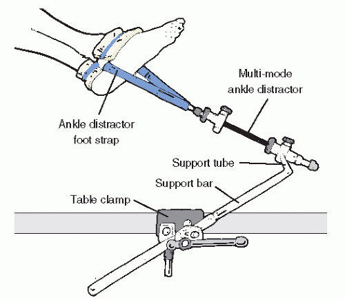
Figure 53.13 Illustration of joint noninvasive joint distraction setup.

It is quite clear that a well-distended, “loose” ankle joint will allow the experienced arthroscopic surgeon access to the majority of the pathology in the anterior two-thirds of the joint. Laxity of the collateral ligaments, allowing inversion of the talus within the mortise, facilitates entry into the lateral gutter and under the anterior syndesmotic ligament and over the talar dome. Strategic dorsiflexion and plantarflexion manipulation of the talus facilitates excellent visualization of the majority of the talar and tibial surfaces of the joint.

In a minority of patients, a tight joint, especially with limited plantarflexion, requires significant physical distraction to see beyond the dorsal most portion of the talus. Degenerative joint disease with significant osteophytosis of the anterior tibial lip impairs visualization of the dome of the talus. Surgical reduction of the impinging anterior lip is helpful in improving visualization. The combination of reduction of the anterior tibial lip and strategic manipulation allows the majority of cases to occur without the need for application of joint distraction. It is, however, recommended that an ankle joint distractor be available for use in the operative setting for all cases that may need this strategy to meet the goals of surgery. Distraction is routinely used in those situations in which the pathology is in the posterior half of the ankle compartment.

Physical distraction of the subtalar joint is usually not necessary because the capsular reflection of the joint usually provides adequate room for instrumentation. Distraction of the great toe joint and intertarsal joints is usually very helpful for adequate joint visualization. A Chinese finger trap-type noninvasive distractor attached to 5 to 15 pounds of distraction or a invasive minirail distractor that bridges the joint is helpful in maintaining adequate working space.


PORTALS

Portals through the soft tissues to the ankle joint are required for passage of the arthroscope and instrumentation. These portals can be safely developed with careful technique and placement. Ideally, once a portal has been developed and the cannula inserted, the cannula can be left in place for safe exchange of instrumentation. With the small instrumentation required for ankle and foot arthroscopy, this procedure is often limited by the lack of availability of instrumentation that fits. Often, instrumentation is carefully inserted into the ankle and other joints of the foot without a cannula. However, overinstrumentation of a portal can lead to creating a large breach of the joint capsule and increase the rate of fluid extravasation into the surrounding soft tissue envelope. Available portals are listed that are commonly in arthroscopic approaches of the foot and ankle (Table 53.1). It is important for the surgeon to be familiar with topographical anatomy; it is more critical to use sound technique to develop portals since superficial nerve position can be variable and prone to injury (29). Portal position can be most critical when the scope needs to cross the articular surface deep into the joint. In this situation, the scope must be tangential to the articular surface. It is sometimes wise to use a needle to double-check portal placements, especially in extremities with large amounts of subcutaneous fat deposition and when ankles are being distracted (since this can cause shifting of topographic landmarks) (Figs. 53.14 and 53.15).


POSTERIOR PORTAL DEVELOPMENT (SWITCHING STICK MANEUVER)

Due to individual variation in the soft tissues surrounding the posterior ankle, it can be difficult to judge the precise location of the joint line and make accurate portal development difficult. A switching stick maneuver can be employed to develop posterior lateral ankle, as well as posterior subtalar portals. The switching stick maneuver in the ankle can be used in a loose or well-distracted joint with instrumentation and scope already present in the anterior compartment, a thin rod or probe with a blunt tip can be directed across the joint from anteromedial to tent the posterolateral capsule. Once an appropriate opening in the skin is made, the rod can be pushed through the soft tissues (30).

In the subtalar joint, a switching stick maneuver can be very useful in developing the posterior portal. This is accomplished by placing the obturator without the cannula in the anterior portal and advancing it along the lateral gutter through the posterior capsule and terminating adjacent to the Achilles tendon. The skin is tented up and incised to expose the obturator tip. The cannula now can be placed over the obturator and accurately placed within the joint.


TABLE 53.1 Common Foot and Ankle Arthroscopic Portals


Joint


Portal


Comment


Ankle


Anteromedial


Common utility portal, usually the first portal developed to inventory the anterior pathology


Anterolateral


Common portal usually used in combination with anteromedial portal. IDCN can be in close proximity to this portal.


Central


Considered an accessory portal, higher risk portal due to proximity of dorsalis pedis and deep peroneal nerve


Posteromedial


This portal is rarely used due to higher risk with neurovascular bundle. Safer if placed adjacent to medial border of Achilles tendon


Posterolateral


Common portal for fluid egress or posterior ankle pathology switch stick accessible


Subtalar


Posterolateral


Common utility portal, especially for posterior subtalar pathology, switch stick accessible


Anterior lateral


Main access portal located at floor of sinus tarsi. Used for anterior, lateral gutter, and posterior access


Lateral central


This portal has higher risk due to proximity of sural nerve generally used egress of fluids.


Accessory anterior


Common use for stacked portal technique when anterior pouch pathology encountered


Posteromedial


Less commonly used, best placed at adjacent to medial border of Achilles. Often necessary portal when treating flexor hallucis longus pathology


First MTPJ


Dorsomedial


Utility portal used in conjunction with dorsolateral portal for dorsal pathology and plantar medial portal for plantar pathology


Dorsolateral


Accessory portal for dorsal joint pathology


Plantarmedial


Less commonly used but necessary for plantar or sesamoid pathology


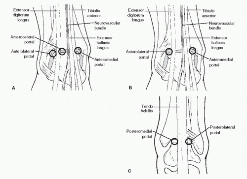
Figure 53.14 Classic portals of the anterior and posterior ankle. A: Anterior three-portal technique. B: Anterior two-portal technique. C: Posterior portal placement.


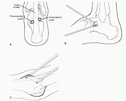
Figure 53.15 Classic portals of the subtalar and great toe joints. A: Posterior subtalar portals. B: Anterior approaches to the subtalar joint. C: First MTPJ portals.


SPECTRUM OF PATHOLOGY

There is a multitude of different conditions that can affect the distal leg, ankle, and hindfoot. Soft tissue impingements are clinically subtle problems at times. The foot and ankle surgeon can find it difficult to accurately determine the precise location of potential pathology due to the close proximity of anatomy. A Careful history and physical examination, accompanied by appropriate imaging, diagnostic injections, and supportive care (including immobilization, and nonsteroidal and steroidal anti-inflammatory medication) usually leads to the appropriate diagnosis. High-resolution computed tomography (CT) and magnetic resonance imaging (MRI), with or without contrast, are quite useful in diagnosing and defining occult pathology within the ankle when routine diagnostic measures do not yield a diagnosis (31). These special diagnostic tools are available in most sites and are preferable to invasive diagnostic strategies in most cases (Fig. 53.16).

Intra-articular soft tissue pathology diagnoses present the most difficulty for traditional diagnostic strategies. Slice width and resolution issues limit the diagnostic efficacy of MRI to 39% sensitivity and 50% specificity with regard to anterolateral impingement syndrome, as compared with 94% and 75% for ankle arthroscopy (31,32). The diagnostic reliability of arthroscopy has been investigated in the knee and other joints, including the ankle, and has been found for most diagnoses to have significant accuracy (33,34,35,36,37 and 38).

An experienced arthroscopist must be able to duplicate or improve on the diagnostic reliability of traditional open surgery and diagnostic imaging techniques, including MRI, if arthroscopy is to be justified. The reduction in surgical morbidity that accompanies ankle and foot arthroscopy should not imply that it should regularly be used for diagnosis. Van Dijk and others have clearly demonstrated that successful outcomes of diagnostic arthroscopy and surgical arthroscopy for nonspecific synovitis (in which appropriate diagnostic attempts have failed) are not frequent (39,40). The arthroscope should usually be regarded as a surgical instrument and not a diagnostic instrument, except in special cases in which one might otherwise perform exploratory or biopsy surgery.


PRIMARY SOFT TISSUE PATHOLOGY

Primary soft tissue lesions are somewhat uncommon in the ankle. Diagnosis is based on history, physical examination, and careful examination of all of the relevant structures. The consideration of intra-articular soft tissue pathology stems from the negative x-ray and or other enhanced imaging studies (CT, MRI, contrast studies, stress x-ray study). Intra-articular injections are often useful in determining whether the pathology is
extra-articular (nonresponsive) or within the joint. A symptom complex that does not respond at least temporarily to an intraarticular injection of local anesthetic with or without steroid will not likely benefit from arthroscopy or other surgical maneuvers. Congenital bands and plicas can be found in the ankle and can cause localized symptoms usually coupled with an increase in activities (Fig. 53.17).


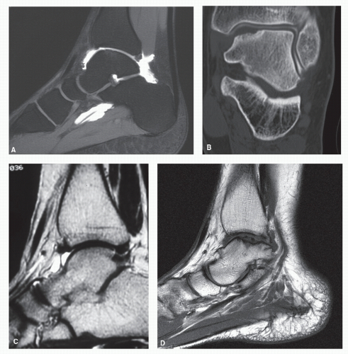
Figure 53.16 Diagnostic images: (A) MRI gadolinium arthrogram sagittal STIR image that shows continuity between the ankle and subtalar joints and the flexor hallucis longus tendon sheath. Note how the study allows enhanced visualization of the cartilage surface with partial thickness cartilage ankle joint defects on the anterior tibial and talar surfaces. B: CT arthrogram after arthroscopic excision of osteochondral fracture fragment. Note fibrocartilage filling of lesion site as highlighted by joint contrast agent. C: MRI arthrogram, sagittal slice on a T1-weighted image highlights intra-articular adhesion in the anterior joint recess. D: MRI demonstrating large osteochondral defect or talus.


HEMORRHAGIC AND CHRONIC SYNOVITIS

A wide variety of abnormal soft tissue anatomy has been described in the ankle; the most common are varieties of reactive hyperplasia of the synovium commonly known as synovitis. With several exceptions, synovitis is a reactive process and not a diagnosis. The synovium of any joint responds to intra-articular pathologic processes by inflammation characterized in the acute setting by hypertrophy, vascular injection, hyperemia, and bright erythema (Fig. 53.18A). An example of reactive synovitis is hemophilic synovitis, which is frequent in hemophilia patients who experience intra-articular bleeding secondary to trauma. Arthroscopic synovectomy of the ankle has been found to reduce the rate of episodes of hemarthrosis in these patients (41,42 and 43).

With chronic inflammatory stimulation, synovium becomes dense and fibrous, losing its bright red color and becoming
white over time (Fig. 53.18B). This hypertrophic tissue can occupy a large portion of the capsular reflection. Hypertrophic synovitis, whether chronic, acute, or mixed, sometimes fills the anterior pouch completely. In some situations, the reactive tissue becomes adherent to the juxta-articular bone and capsule. This condition is sometimes termed adhesive capsulitis because the tissue tends to contract, ultimately limiting movement and becoming impinged at the anterior joint line. Resection of adhesive capsulitis is frequently necessary to visualize the joint and define or discover the primary lesion, if it is still present.


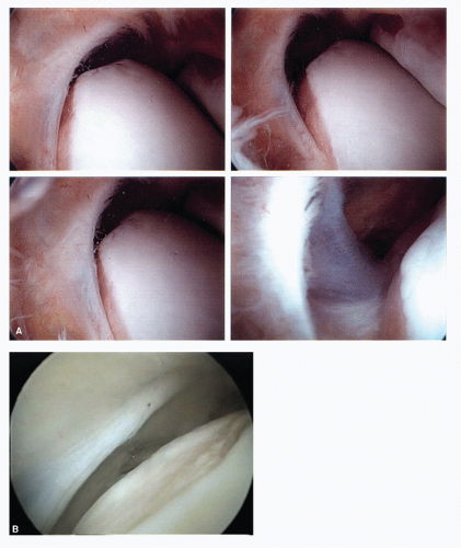
Figure 53.17 A: Anterior lateral ankle capsule with congenital band showing interaction with anterior talar body in different ankle positions. B: An example of a linear-oriented congenital band causing talar dome erosion. Note these bands are localized thickenings of the joint capsule and are covered by synovium.

Synovial disorders that present as primary disorders include pigmented villonodular synovitis (Fig. 53.18C), rheumatoid arthritis, and related autoimmune diseases. Synovial resection for biopsy and therapy in primary synovial disorders is clearly beneficial. Synovial resection in nonspecific synovitis or in which synovitis is clearly secondary to an identifiable pathologic problem can be limited to that which is clearly impinged, obscuring or limiting the surgical procedure. Once the primary causation is resolved, one can expect spontaneous resolution of the reactive process.


FIBROUS BANDS AND MENISCOID LESIONS

Other soft tissue masses encountered in the ankle are not of synovial origin but are likely related to retained intra-articular blood clots secondary to trauma (44,45). Fibrous bands,
meniscoid lesions, impingement lesions, and adhesions are all similar lesions that are characterized as well-defined fibrocartilaginous bodies attached to periarticular structures, occasionally to bone and cartilage (Fig. 53.19) (46,47,48 and 49).

Only gold members can continue reading. Log In or Register to continue

Stay updated, free articles. Join our Telegram channel

Jul 26, 2016 | Posted by in MUSCULOSKELETAL MEDICINE | Comments Off on Arthroscopy of the Ankle and Foot

Full access? Get Clinical Tree

Get Clinical Tree app for offline access