Fig. 17.1
2 % Lignocaine with adrenaline solution in 1:200,000 dilution is injected to portal sites for hemostasis effect
Once the arthroscope is being inserted, particular attention is paid to assess the status of the interosseous ligaments, the degree of synovitis, and the articular cartilage condition of the joints intended to be fused and the other uninvolved joint compartments of the wrist. The latter is essential to determine whether the proposed fusion is appropriate or not. The dorsal rim of the radial styloid is a common site of occurrence of the early SLAC or SNAC wrist arthritic changes and should be assessed in all cases by rotating the 30° forward slanting lens downward to reach the area. The frequently associated localized posttraumatic synovitis in this area may obscure the observation of cartilage condition. The synovial growth needs to be eliminated by using a 2.0 mm shaver or a radiofrequency probe inserted from 4/5 portal. It may be necessary to swap the portal of the arthroscope and instrument in order to obtain a better attacking angle of the instrument for a more efficient synovectomy. The ulnocarpal joint should also be routinely inspected and the status of TFCC ascertained. Any central perforation of the TFCC without peripheral involvement should be debrided of any unstable flap tear at the same operation to avoid possible new source of pain after the definitive index procedure.
The midcarpal joint is approached through the MCR portal. Routinely the STT joint, scaphocapitate joint, capitolunate joint, and triquetrohamate joint are inspected for cartilage lesion and synovitis. The scapholunate and lunotriquetral joint are assessed for stability with a 2 mm probe introduced from the MCU portal. Any instability is graded according to the Geissler classification. Synovial overgrowth should be debrided by using a shaver or radiofrequency probe to adequately expose the underlying cartilage area for assessment of the true extent of chondral damage and subchondral bone exposure. In posttraumatic arthritis, difficulty may be encountered when developing the radial portal at the midcarpal joint due to the intra-articular adhesion and periarticular soft tissue contracture. Under this circumstance, one should not hesitate to shift to the midcarpal ulnar portal where joint space is usually more generous. Once the joint is entered, the other portal can be developed more easily by applying an 18G needle through the skin under direct vision. This greatly helps the localization of any difficult portal. A prerequisite for a successful radio-carpal fusion is a relatively intact articular surface at the midcarpal and STT joints. If significant arthritic change is present, one may need to abandon the planned procedure and consider other salvage option such as total wrist fusion. Two accessory portals may also be recruited during any midcarpal procedure. The triquetrohamate (TH) portal can be located by palpating the tendon of ECU and moving distally until the palpating finger reaches the hamate bone. The portal is then located at the axilla between the ECU tendon and the hamate. It is most useful as an outflow portal. The scapho-trapezial-trapezoid (STT) portal is situated about 1 cm radial and slightly distal to the MCR portal just ulnar to the EPL tendon slightly distal to the MCR portal. The portal is located at the junction between the scaphoid, trapezoid, and trapezium. Care should be taken in avoiding injury to the radial artery which is radial to the EPL tendon.
Cartilage Denudation
The articular surfaces of the joint compartments to be fused are then prepared. The extent and depth of cartilage denudation should be precisely controlled using a 2.9 mm arthroscopic burr. In debriding the carpal interval of the same carpal row, such as lunotriquetral or capitohamate interval, a smaller burr such as 2 mm sized should be used to cater for the narrower joint space to avoid excessive cartilage and subchondral bone removal. Either forward or reverse blade rotation mode should be adopted at a speed of 2,000–3,000 rpm. Oscillating mode is not as effective as compared to the unidirectional mode. One should be cautious about the jumping phenomenon when using a burr to attack a particularly sclerotic bone surface. The burr may get caught in the area of hard subchondral bone during the high speed revolution. The resultant force will bounce the burr off the bone and may lead to accidental damage of the articular surface of the surrounding or opposing carpal bones. To have better control of the instrument, the surgeon is recommended to hold the arthroscopic burr near the far end with the surgeon’s thumb and index finger, while using the middle finger to firmly anchor the burr over the skin around the portal site (Fig. 17.2). There should be maximal preservation of the subchondral bone so as to maintain carpal height. Burring is completed when the subchondral cancellous bone with healthy punctate bleeding is reached. This phenomenon can be easily observed if a tourniquet is not used during this process (Fig. 17.3). Usually bleeding is limited and can be well controlled with the hydrostatic pressure applied through the irrigation system. If bleeding is profuse, one may further elevate the suspension of the instilling saline bag to increase the hydrostatic pressure, or use the coagulation mode of the radiofrequency apparatus. During the burring process, suction is switched on and off intermittently to remove any accumulated bone debris which may block the visual field. If suction is applied continuously during the burring process, excessive air bubbles drawn in will severely compromise the visibility of the operating site.
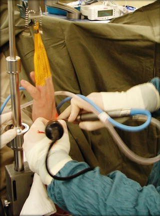
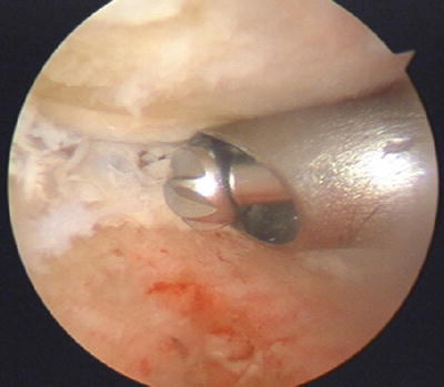
Fig. 17.2
To have better control of the instrument, the arthroscopic burr is being held near the far end with the surgeon’s thumb and index finger, while the middle finger firmly anchors the burr over the skin around the portal site
Fig. 17.3
Punctate bleeding can be readily seen from the subchondral bone during burring without the use of tourniquet
Correct Carpal Deformity
DISI deformity is commonly present in many posttraumatic wrist arthritis conditions. It is prudent to correct the deformity as far as possible during the process of partial wrist fusion involving the capitate-lunate joint in order to maximize the motion and to reduce abnormal loading through the lunate fossa. A close reduction can be accomplished by correcting the radio-lunate angle to zero degree using a K wire to transfix the radiolunate joint with the wrist in moderate flexion and slight ulnar deviation (Fig. 17.4). A 1.1 mm K wire is introduced percutaneously through a small stab wound over the distal radius slightly proximal to the sigmoid notch level, aiming at the level between the 3/4 and 4/5 portals. A fine tip hemostat or stitch scissor should be used to dissect bluntly the extensor tendons to avoid iatrogenic injury or tethering of the extensor tendons during the introduction of K wire through the skin. The precise location of the insertion point and insertion angle should be guided by an image intensifier both in the antero-posterior and lateral projection. The K wire should not perforate through the distal cortex of lunate so as to leave a space at the capitate-lunate joint. Before the final fusion progress, the other carpal bones are realigned manually in relation to proper lunate position.
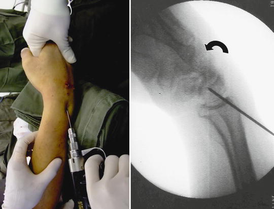
Fig. 17.4
DISI deformity of the lunate can be closely reduced by flexing the wrist and transfixing radiolunate interval at an anatomical alignment before reduction of other carpal bones in relation to lunate
Provisional Fixation of the Carpal Fusion
The wrist is dislodged from the wrist traction tower and is placed horizontally over a hand table for the provisional fixation. The carpal interval(s) to be fused is temporarily fixed with 1.0 or 1.1 mm K wire percutaneously using a powered driver in an anatomical position as far as possible. Alignment is confirmed with an intraoperative image intensifier. The K wires can be used as definitive fixation device or they can be used as the guide pins for the subsequent conversion into percutaneous cannulated screw fixation. The pins are then withdrawn to free from the joint to be fused while they are maintained in position in the carpal bone or distal radius. Externally the pins should be protected with pin caps to avoid accidental injury to the surgeon’s hand in the remaining process. The joint is then ready for grafting with autogenous cancellous bone or bone substitute.
Augmentation of the Fusion Segment(s) with Bone Graft or Bone Substitute
Autogenous bone graft or bone substitute is frequently required to fill up the voids between the articular surfaces to be fused. As the vascularity and the bone quality of the fusing bones are usually adequate, cancellous chip graft from iliac crest may not be essential and there is an increasing role of using bone substitute to reduce the potential donor site morbidity with similar outcome. Both injectable form and small granule form are suitable for the purpose. In order to prevent spillage of the graft inside the joint to the undesirable compartments, special Foley catheter balloon blocking technique has been developed (Fig. 17.5). A French size 6 Foley catheter with a stylet on is introduced through the arthroscopic portal. The tip of the catheter is usually cut short to allow better placement of the balloon. Advancement of the catheter into the joint can be facilitated by grasping the tip of the catheter using a small arthroscopic grasper introduced from a third portal. Once the balloon portion of the catheter is completely inside the joint as monitored through the arthroscope, it can be inflated with saline solution until the joint compartment away from the fusion interval is largely obliterated by the balloon. The balloon remains inflated during the arthroscopic bone graft process so that redundant cancellous graft or bone substitute will not fall into and be trapped in other compartments not going to be fused. Reducing fluid inflow is also a useful trick to avoid graft spillage.
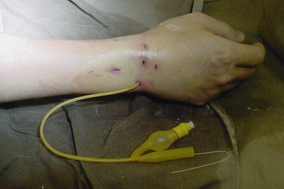
Fig. 17.5
Foley catheter blocking technique to avoid spillage of bone graft/substitutes to the uninvolved space
An arthroscopic cannula is introduced through the appropriate portal directly opposing the fusing surfaces. If autogenous graft is to be used, cancellous bone graft is harvested from the iliac crest using either trephine technique or an open approach through a small incision. The bone graft is then cut into small chips using scissor and delivered through the cannula with a slightly undersized trocar with a flat end such as the bone biopsy trocar into the joint cavity (Fig. 17.6). Trocar with roundish end is not effective enough. Too exact fitting of the trocar in the cannula will cause an easy trapping of bone graft substance between the trocar and cannula wall and may lead to delivery problem. So a slightly undersized trocar is more desirable. The bone graft is impacted with the trocar till satisfactory volume of graft is achieved (Fig. 17.7). This process requires two assistants to execute smoothly. One assistant helps to maintain the position of the arthroscope to provide optimal vision of the fusion site. The operating surgeon controls the arthroscopic cannula and trocar. A second assistant is responsible to deliver the bone graft or bone substitutes into the opening of the cannula in small volume every time. The operating surgeon then drives the bone graft or substitute into the fusion site under directly arthroscopic monitor (Fig. 17.8). The speed of the process can be enhanced by using a cannula of wider bore such as 4.5 or 5 mm so that each time more graft can be accommodated. If injectable bone substitute is to be used, joint irrigation should be ceased and all joint fluid evacuated with suction. A wide bore needle connecting the syringe containing the bone substitute is inserted through appropriate portal to reach the fusion site. Injection of the bone substitute can then be performed under direct vision till the cavity is filled up completely. If necessary, intraoperative fluoroscopy can help to confirm the completeness of the filling process.
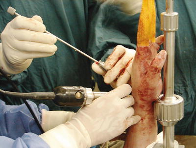
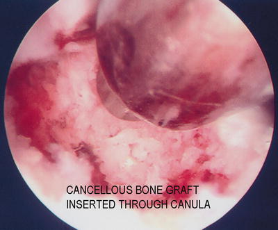
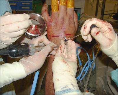
Fig. 17.6
Bone graft is delivered through a cannula with a slightly undersized trocar of flat end such as the bone biopsy trocar into the joint cavity
Fig. 17.7
Impaction of graft with blunt trocar at fusion site
Fig. 17.8
With the help of two assistants, the operating surgeon controls the arthroscopic cannula and trocar and drives the bone graft or substitute into the fusion site under direct arthroscopic monitor
Definitive Fixation
The wrist is taken off from the traction tower again and placed in the hand table. Definitive fixation is performed by driving the K wires across the bony interval to be fused and in a correct carpal alignment. If cannulated screw is preferred, the K wires will then serve as the guide pins. After measuring the length of the screw required, the pin tract is drilled using a cannulated drill bit. Stable internal fixation can then be achieved with compression screw using appropriate percutaneous cannulated screw system, preferably a headless screw system to avoid screw head impingement. The final carpal alignment, screw position, and length should be assessed by using an image intensifier. In older patient with osteoporotic bone, multiple K wires fixation is preferred over screw fixation to avoid hardware problem, such as the protrusion of screw tip into the joint (Fig. 17.9). Percutaneous K wires should be cut short and buried underneath the skin. They are removed under local anesthesia when the bone healing is complete. Exposing pins outside skin may predispose to pin tract infection. The wrist is then immobilized with a plaster slab.
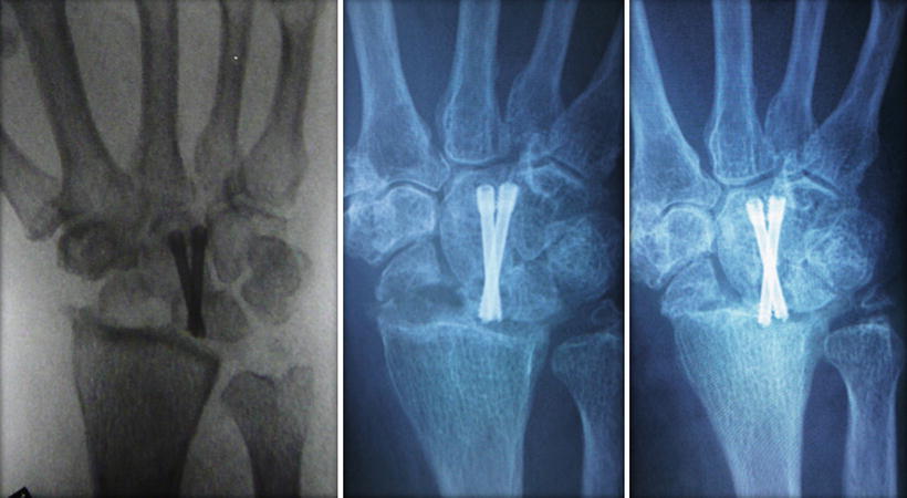
Fig. 17.9
Self-tapping headless screw may protrude into the joint gradually during healing process of the fusion site in old patient with osteopenic bone
Specific Fusion Technique and Rehabilitation
STT Fusion
STT fusion is commonly indicated in stage 1 or II SLAC wrist, Kienbock disease stage 3a or 3b and STT joint arthritis [16–18]. It is frequently performed together with a radial styloidectomy, which can also be accomplished under an arthroscopic mean. The best indication for arthroscopic STT fusion is STT joint arthritis, with or without association with SLAC wrist. Under such circumstance, there is usually no scaphoid mal-alignment and hence no DISI deformity needed to be correct.
Radiocarpal joint arthroscopy should be routinely performed to look for arthritic changes over the radioscaphoid and radiolunate joints. Arthritic change in the former compartment may make the radial styloidectomy a necessary accompanying procedure while change in the latter compartment may constitute a contraindication of the procedure.
Arthroscopic STT fusion is then performed at the midcarpal joint. The STT portal is often required to provide a direct access to the STT joint. The arthroscope is inserted in the MCR portal and directed towards the STT joint by climbing up the slanting articular surface of the scaphoid over the waist portion opposing the capitate till the scapho-trapezoid-capitate junction is reached. The latter is signified by an inverted Y shaped joint interval which I call it as “Mercedes Benz” sign (Fig. 17.10). In STT arthritis condition, the joint is frequently obliterated by synovial overgrowth and joint debris (Fig. 17.11). They need to be cleared up with a shaver and/or radiofrequency probe before the articular cartilage condition can be verified. The joint space may also be contracted with the periarticular soft tissue fibrosis. Joint entry can be facilitated by using a smaller arthroscope such as 1.9 mm. Sometimes the joint space in the whole radial compartment of the midcarpal joint may be compromised and one should not hesitate to start the joint exploration through the ulnar midcarpal portal, which is always less affected under such circumstances. Nevertheless, joint space usually gets enlarged after a period of joint debridement procedure and manipulation to allow sufficient access for the subsequent grafting procedure with bigger instruments. The arthritic joint surface is then debrided of the remaining articular cartilage till subchondral bone is exposed. Initially the trapezium may be difficult to reach as it is situated in deeper space at the STT joint. As long as the cartilage surface of the distal scaphoid and trapezoid is removed with arthroscopic burr, there is progressively more space for the burr to reach the surface of the trapezium. Due to the relatively tight space, bleeding from bone ends may obscure the operative field and tourniquet may be required to control bleeding at this junction temporarily. The proximal part of the articular surface between the trapezium and trapezoid should also be denuded of cartilage with an arthroscopic burr. However complete take down of the articular surface is probably not necessary as normally the TT joint is very tight and stable.
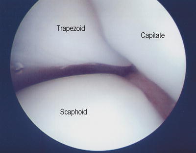
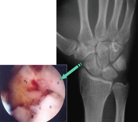
Fig. 17.10
Mercedes Benz sign at junction between capitate, trapezoid, and scaphoid
Fig. 17.11
Radiological and arthroscopic view showing typical posttraumatic STT joint arthritis with synovial overgrowth and eburnation at joint surface
Once the articular surface for fusion is well prepared, a percutaneous fixation of the STT joint can be performed. Fixation can be in ththe form of K wires transfixing scapho-trapezial, scapho-trapezoid, and trapezio-trapezoid joints. I prefer to employ rigid fixation using a cannulated screw with compression inserted from trapezium to scaphoid percutaneously. Fixation of the scapho-trapezoid and trapezio-trapezoid joints then becomes nonessential. With the hand placed horizontally in hand table, a guide pin is inserted through a small stab wound at junction between base of first metacarpal and the trapezium under an image guidance with the aim towards the proximal pole of the scaphoid (Fig. 17.12). Alignment should be confirmed by at least four radiological views of AP, lateral, semi-supinated AP, and semi-pronated PA view. If scaphoid is abnormally flexed and pronated due to scapholunate instability, a 1.6 mm K wire can be inserted percutaneously to be used as joystick to correct the alignment of scaphoid. With the arthroscope in MCR portal, a small probe can also be inserted through STT portal to assist the reduction of scaphoid alignment by hooking onto the distal part of the scaphoid to extend and derotate the scaphoid. The K wire inserted through trapezium can then be driven through to reach the proximal scaphoid.
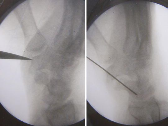
Fig. 17.12
Intra-op X-ray view showing placement of starting awl over the distal tubercle of trapezium and the guide pin insertion across scapho-trapezial joint
The arthroscope is then inserted again into the joint through MCR portal to verify the position of K wire (Fig. 17.13). If the joint space at STT joint becomes too tight to allow bone grafting through an arthroscopic cannula, the K wire can be withdrawn from the scaphoid but remains attached to the trapezium. Autogenous bone graft or bone substitute can be inserted through a small cannula as described above to fill up the void (Fig. 17.14). The K wire is then driven back into the scaphoid till the subchondral surface of proximal scaphoid is reached. Length of the inserted portion of the K wire is measured. The screw length should be 2 mm short of the measured length to reduce the possibility of perforation of the proximal articular surface of scaphoid. The K wire is then driven further proximally, perforating the proximal pole of scaphoid and exiting outside skin near the 3/4 portal of radiocarpal joint. The tip of the K wire is grabbed with a hemostat. This trick helps to prevent accident pull off of the K wire during subsequent drilling process with the small cannulated drill. The bone is then drilled with a cannulated drill bit and finally the trapezio-scaphoid joint is transfixed with an appropriate cannulated screw with compression for added stability (Fig. 17.15). The guide wire can be removed afterward. Final alignment of the screw should be confirmed using an image intensifier. The midcarpal joint is then surveyed with an arthroscope to check for any spilled out graft material, which should be removed by using a mosquito grasper or flushed out from the canula with saline.
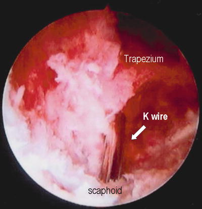
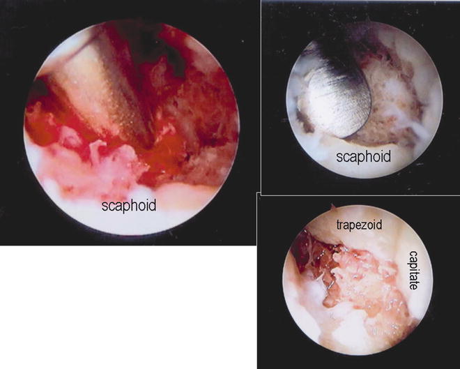
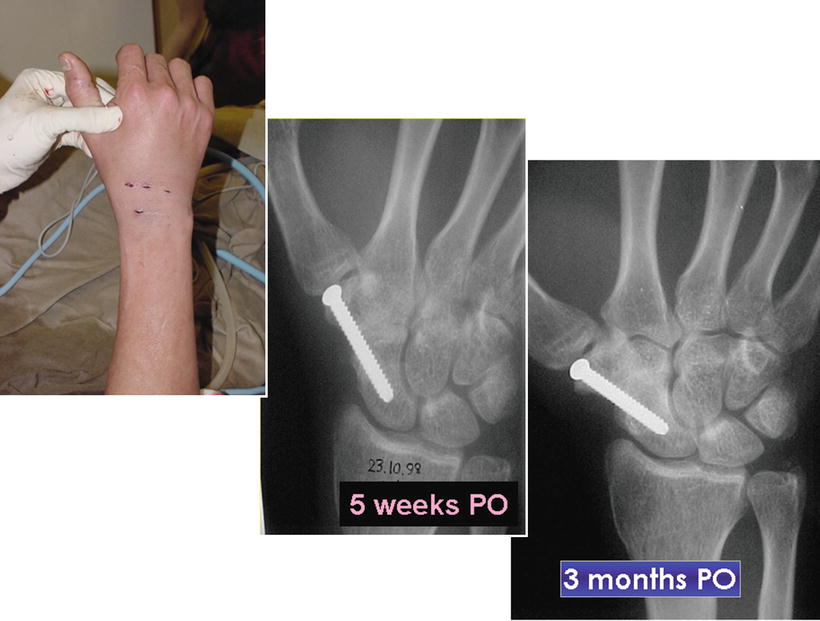
Fig. 17.13
Verification of the guide pin position at the STT joint as viewed through the arthroscope
Fig. 17.14
Delivery of autogenous bone graft through cannula to the fusion site, impaction, and final appearance
Fig. 17.15
Final wound appearance and progress of radiological changes showing early union at 5 weeks and consolidation over 3 months post-op
Wounds are closed with steri-strips and a comfortable bulky dressing is applied supported with a short arm plaster slab. The slab is changed to a removable scaphoid splint after the first week. Active mobilization of the wrist is allowed out of splint under supervision of a hand therapist. Passive wrist mobilization and strengthening exercise can be offered when radiological and clinical union is evidenced, usually around 10–12 weeks post-op (Fig. 17.16).
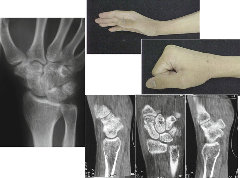
Fig. 17.16
X-ray, CT, and clinical features confirming solid union of the STT joint fusion
Four Corners Fusion
Four corners fusion is indicated when there is significant peri-scaphoid arthritis in the presence of a relatively intact radio-lunate joint (Fig. 17.17). Under these circumstances, the scaphoid is usually removed surgically as a concomitant procedure with the four corners fusion. Presence of severe arthritic change at the midcarpal joint will exclude the alternative option of proximal row carpectomy and makes the operation a procedure of choice [19, 20]. For pathology that does not involve radioscaphoid arthritis, the indications include midcarpal instability, isolated midcarpal arthritis, or lunotriquetral dissociation with fixed volar intercalated segmental instability alignment of the lunate. When performing four corners fusion in cases without radioscaphoid arthritis, Taleisnik favored scaphoid inclusion [21] and Weiss et al. preferred scaphoid retention [22]. In a cadaveric study carried out by Kobza et al., it was shown that simple four corners fusion with scaphoid retention led to a significant decrease in extension, radial deviation, and ulnar deviation [10]. Four corners fusion with scaphoid excision allowed significantly greater radial deviation but also led to significant increase in radiolunate contact area and the mean contact pressure. However the clinical impact was not known.
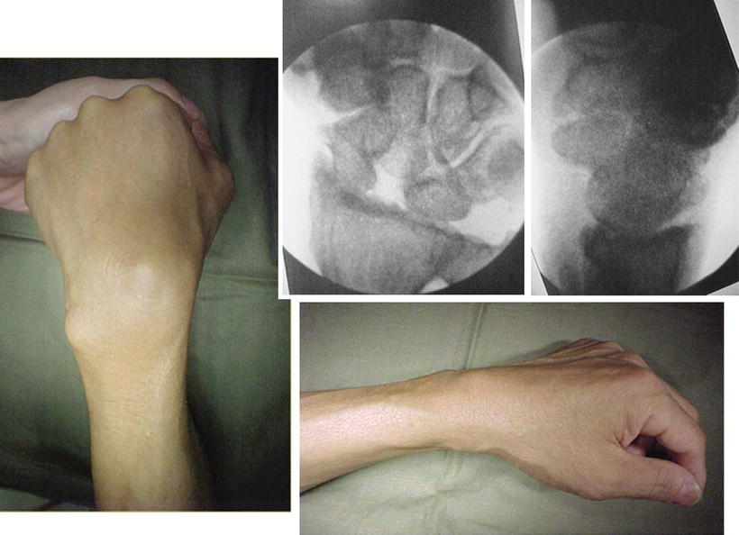
Fig. 17.17
A 47-year-old manual worker with SLAC wrist stage III undergoing arthroscopic scaphoidectomy and four corners fusion at Sept 2000
We reported four cases of arthroscopic four corners fusion with scaphoidectomy in 2008 [23]. The operation should begin with a surveillance of the radio-carpal joint to confirm an intact radio-lunate articulation and preferably an intact proximal articular surface of triquetrum. Arthroscopic scaphoidectomy is then performed from the midcarpal joint. The operation can be performed without a tourniquet provided that the portal sites and joint space are infiltrated with adrenaline solution in lignocaine. With the arthroscope introduced from the MCU portal, an arthroscopic burr of 2.9 mm is inserted into MCR portal and directed towards the proximal and mid-scaphoid region. The scaphoid is burred at high speed from the articular surface down to the core cancellous bone. Bone debris is removed by intermittently applied suction. To avoid accidental damage of the adjacent articular surfaces to be preserved, a shell of cartilage can be left intact until majority of the cancellous bone is removed. This shell of cartilage can help to separate the burr from the adjacent carpal bone during the burring process (Fig. 17.18). This can be removed piecemeal at the end of the scaphoidectomy procedure by using a small pituitary rongeur or an arthroscopic punch (Fig. 17.19). When taking out the larger piece of bone fragment, it is advisable not to use excessive violence in order to avoid damage to the attaching ligament and soft tissue structure. One trick is to firmly grip on the bone fragment with the small rongeur using both hands while to twist around its own axis and maintain a gentle pulling force. The fragment will gradually lose its connection to the soft tissue and can be delivered smoothly out of the joint. During the delivery process, the surgeon has to maintain a sustained and firm grip on the bony fragment or otherwise it may get lost in the juxta-articular or subcutaneous tissue plane. Under such situation, the surgeon may be forced to enlarge the surgical wound in order to remove the retained bony fragment, which is not desirable (Fig. 17.20). In order to speed up the process, an arthroscopic burr of progressive increase in size such as 3.5 mm and even 4.5 mm can be used when there is more space opened up after part of the scaphoid is removed (Fig. 17.21). The speed of scaphoid excision can often be doubled or even tripled. Alternatively a small osteotome can also be used to break the bone into piecemeal for easier removal. Extreme care has to be exercised during insertion of the larger burr or osteotome to avoid iatrogenic injury to the extensor tendon and cutaneous nerve. The distal few millimeters of the scaphoid can be left in situ so as to preserve the scapho-trapezial ligament. The distal scaphoid tubercle does not normally articulate with the radial styloid and hence its preservation will not cause impingement pain postoperatively.
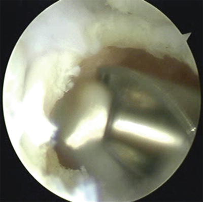
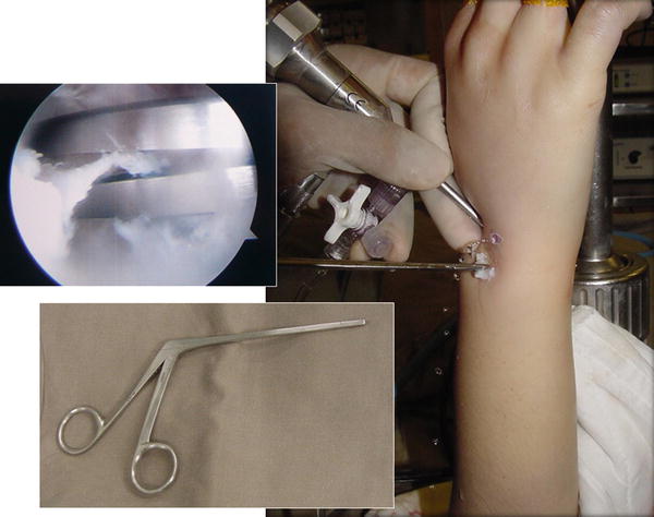
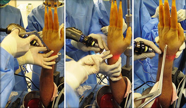
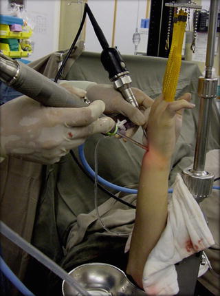
Fig. 17.18
Shell of cartilage left intact during burring of scaphoid to protect other uninvolved articular surface
Fig. 17.19
Cartilage shell removed in piecemeal using small pituitary rongeur inserted through portals
Fig. 17.20
The surgeon firmly grips on the bone fragment with the small rongeur using both hands while to twist around its own axis and maintain a gentle pulling force. The fragment will gradually lose its connection to the soft tissue and can be delivered smoothly out of the joint
Fig. 17.21
Use of large 4.5 mm arthroscopic burr helps to speed up the burring process
Once scaphoid is cleared, attention can be paid to the fusion of the midcarpal joint at the four corners region. The arthroscope is now inserted through MCR portal while the MCU portal is reserved for the arthroscopic instruments. The articular surface between the capitate, lunate, triquetrum, and hamate is denuded of cartilage with 2.9 mm burr. The joint surface of the luno-triquetral joint is also burred. I do not routinely burr the articulation between hamate and capitate as the joint is very rigid normally.
After an adequate cartilage destruction, provisional fixation is performed under an image intensifier’s guide. If there is significant ulnar translocation and DISI deformity of the lunate and radial subluxation of the capitate off the lunate margin, the lunate is reduced by gentle flexion and radial translation of the wrist so as to restore the normal radio-lunate relationship. The aim is to have at least half of the lunate sitting over the distal radius. The lunate is then fixed to the radius with a percutaneous K wire of 1.1 or 1.6 mm inserted from the distal radius.
The capitate is then reduced by ulnar translation of the wrist so that it sits as much as possible on the distal lunate articular surface (Fig. 17.22). A percutaneous K wire is inserted from the dorsal surface of the capitate at the distal junction with the base of the third metacarpal under an image guide (Fig. 17.23). The mini-stab wound should be bluntly dissected to avoid iatrogenic injury to the extensor tendon. With the help of a lateral projection on the image guide, the K wire is driven across the capitolunate joint to anchor into the lunate. The angle of attack has to be acute enough in order to catch the central part of the lunate to have a better purchase of the bone. It is most crucial to obtain a good surface contact of the capitolunate joint as the key point of the operation is to achieve solid fusion of the CL joint to avoid late collapse of the midcarpal joint and hence loss of the carpal height.
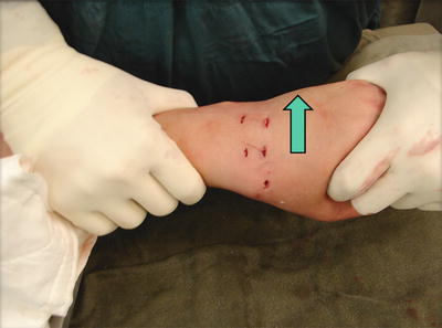
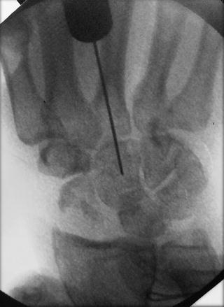
Fig. 17.22
The capitate is reduced by ulnar translation of the wrist so that it sits as much as possible on the distal lunate articular surface
Fig. 17.23
Guide pin inserted through distal capitate to transfix capitolunate joint
If satisfactory alignment can be achieved, the K wire is withdrawn from lunate while still attaching to the capitate. This is then followed by the bone grafting procedure at the midcarpal joint as described in session before. With the arthroscope held at MCR portal, the cannula can be inserted through the MCU portal for bone graft or substitute delivery. If scaphoidectomy is included, a French size 6 Foley catheter is inserted via the 3/4 portal to completely obliterate the empty space left after the scaphoidectomy procedure. The balloon is inflated while bone graft or substitute is being delivered to the ulnar midcarpal space (Fig. 17.24). The catheter can be removed after the bone grafting procedure, or can be left in situ for a day or two to serve as a surgical drain.
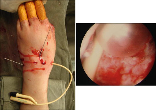
Fig. 17.24
 Arthroscopic Management of Distal Radius Fractures
Management of Ulnar Impaction
Wrist Arthritis: Arthroscopic Techniques of Synovectomy, Abrasion Chondroplasty, Radial Styloidectomy, and Proximal Row Carpectomy of the Wrist
Suture-Button Suspensionplasty for the Treatment of Thumb Carpometacarpal Joint Arthritis
Arthroscopic and Open Radial Ulnohumeral Ligament Reconstruction for Posterolateral Rotatory Instability of the Elbow
Management of Scapholunate Ligament Pathology
Arthroscopic Management of Distal Radius Fractures
Management of Ulnar Impaction
Wrist Arthritis: Arthroscopic Techniques of Synovectomy, Abrasion Chondroplasty, Radial Styloidectomy, and Proximal Row Carpectomy of the Wrist
Suture-Button Suspensionplasty for the Treatment of Thumb Carpometacarpal Joint Arthritis
Arthroscopic and Open Radial Ulnohumeral Ligament Reconstruction for Posterolateral Rotatory Instability of the Elbow
Management of Scapholunate Ligament Pathology


A French size 6 Foley catheter is inserted via the 3/4 portal to completely obliterate the empty space left after the scaphoidectomy procedure
Related posts:
Arthroscopic Management of Distal Radius Fractures
Management of Ulnar Impaction
Wrist Arthritis: Arthroscopic Techniques of Synovectomy, Abrasion Chondroplasty, Radial Styloidectomy, and Proximal Row Carpectomy of the Wrist
Suture-Button Suspensionplasty for the Treatment of Thumb Carpometacarpal Joint Arthritis
Arthroscopic and Open Radial Ulnohumeral Ligament Reconstruction for Posterolateral Rotatory Instability of the Elbow
Management of Scapholunate Ligament Pathology
Stay updated, free articles. Join our Telegram channel
Full access? Get Clinical Tree
