Ankle Malunions
Bradley M. Lamm
John E. Herzenberg
Ankle deformities are congenital, dysplastic, developmental, or traumatic in origin. Patients with ankle deformities have isolated or combined osseous malalignment and soft tissue contractures with or without limb-length discrepancies. Varying degrees of degenerative joint disease is a common finding in cases of ankle malunion. A comprehensive analysis of the ankle deformity with accurate assessment of adjacent joint compensation is essential for a successful surgical outcome.
Limb deformity principles are the foundation for proper surgical planning and correction. They provide accurate reference points for producing predictable results. The geometrically based principles originate from a standard set of radiographic angles and reference points (Fig. 113.1) (1). Ankle deformity correction requires extensive surgical experience because of the multiple factors that are necessary to consider and address for a successful outcome.
Ankle malunion results from either an improperly reduced fracture or an improperly fused ankle. Sequelae of a malaligned ankle include subtalar degeneration, reduced foot flexibility, compensatory foot deformities, and pain with ambulation. Fractures of the ankle vary from isolated or combined fractures of the tibia, fibula, and talus. Pilon and intraarticular fractures typically are more difficult to acutely realign and therefore are more likely to become malunited and lead to subsequent arthritis of the joint. Malunion of the ankle can also be created by a poorly positioned ankle fusion. Correction of malaligned ankle fusion is thus critical to preserve the functional mobility of neighboring joints. The optimal ankle fusion position has been reported (2,3), and when the ankle is fused ignoring optimal position, many complications occur. Limb deformity principles and considerations regarding surgical realignment of an ankle malunion are highlighted throughout this chapter.
EVALUATION, DIAGNOSIS, AND FUNCTIONAL ANATOMY
CLINICAL AND RADIOGRAPHIC EVALUATION OF DEFORMITY
In addition to pertinent medical and surgical histories, a detailed history of the cause and resultant effects of the deformity should be elicited. Knowing the cause of the ankle deformity is essential to understanding the current ankle problem. Performing a thorough physical examination to include clinical evaluation, observing patients during gait and stance, and determining the patient’s goals are very important.
It has been well documented that an understanding of radiographic angular relationships is critical for appropriate evaluation and identification of the level and extent of deformity (1). Obtaining accurate radiographs is essential for surgical planning. Erect lower limb radiographs (full lower extremity, including pelvis, femur, tibia, fibula, and foot) and long lateral view radiographs (full lower extremity, including femur, tibia, fibula, and foot) are important for measuring overall lower extremity alignment, joint orientation angles, and limb-length discrepancies. They also are essential for locating the center of rotation of angulation (CORA), or apex, of the deformity (1). To assess limb-length discrepancy and proximal deformity, the long radiographs should be obtained even though deformity is isolated to the foot and ankle. If no proximal deformity or limb-length discrepancy is suspected, the long films should at least include the entire tibia. On the erect lower limb radiograph, a limb-length discrepancy cannot be accurately measured for patients with fixed ankle equinus or fixed knee flexion deformity.
It is important to obtain routine anteroposterior and lateral view radiographs of the foot and ankle; however, frontal plane alignment of the hindfoot is not well visualized on those views. Harris and Beath (4) described a frontal plane radiograph of the heel, which was later modified by Kleiger and Mankin (5) (posterior tangential view) into what is now known as a long calcaneal axial view. A long calcaneal axial view radiograph shows the relationship of the calcaneus to the leg and the subtalar joint (Fig. 113.2). Another frontal plane technique was described by Cobey (6) in 1976 and was later modified by Saltzman and el-Khoury (7). This hindfoot alignment view (or Saltzman view) allows visualization of the ankle joint together with the relationship of the body of the calcaneus to the tibia (Fig. 113.3) (1,6,7). These frontal plane radiographs provide essential information regarding the tibial-calcaneal relationship (Fig. 113.4).
To assess the position of the foot during gait, the radiographs should be obtained with the patient bearing weight. A mortise lateral view radiograph is important for accurate measurement and visualization of the tibial plafond, talar dome, and anterior ankle osteophytes (Fig. 113.5). Stress radiographs also are important to differentiate soft tissue abnormalities from osseous deformities. Maximum ankle dorsiflexion radiographs aid in assessment of equinus versus osseous anterior ankle impingement. Real-time fluoroscopy adds a fourth dimension to the evaluation of ankle, subtalar joint, and midfoot motion (1).
DEFINITIONS
The mechanical axis of the lower extremity is the line from the center of the femoral head to the center of the ankle plafond. Mechanical axis deviation (MAD) is the perpendicular distance from the mechanical axis of the lower extremity line to the center of the knee joint (Fig. 113.6). The mechanical axis of the tibia is the line from the center of the knee joint to the center of the ankle plafond (Fig. 113.7). The anatomic axis
of the tibia is the middiaphyseal line of the tibia (Fig. 113.8). A joint orientation angle is the angle between the anatomic or mechanical axis of the bone and the joint line in either the frontal or sagittal plane. Joint orientation angle nomenclature is presented in Figure 113.1.
of the tibia is the middiaphyseal line of the tibia (Fig. 113.8). A joint orientation angle is the angle between the anatomic or mechanical axis of the bone and the joint line in either the frontal or sagittal plane. Joint orientation angle nomenclature is presented in Figure 113.1.
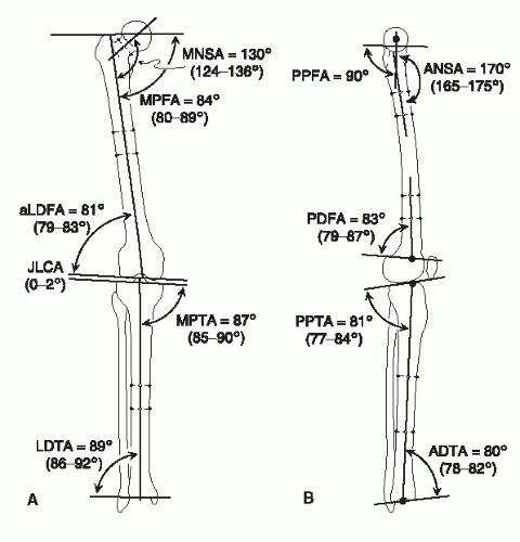 Figure 113.1 A: Normal joint orientation angles and nomenclature in the frontal plane, as referenced by the anatomic axis. B: Normal joint orientation angles and nomenclature in the sagittal plane, as referenced by the anatomic axis. ADTA, anterior distal tibial angle; aLDFA, anatomic lateral distal femoral angle; ANSA, anterior neck shaft angle; JLCA, joint line convergence angle; LDTA, lateral distal tibial angle; MNSA, medial neck shaft angle; MPFA, medial proximal femoral angle; MPTA, medial proximal tibial angle; PDFA, posterior distal femoral angle; PPFA, posterior proximal femoral angle; PPTA, posterior proximal tibial angle. (From Paley D, ed. Principles of deformity correction. Berlin, Germany: Springer-Verlag, 2003, with permission.) |
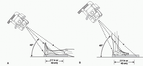 Figure 113.2 A: Long calcaneal axial view radiograph can be obtained with the patient in a non-weightbearing or supine position, such as on the operating room table. The foot is at 90 degrees to the leg, while the x-ray beam is angled at 45 degrees to the cassette. The cassette should be large enough to include the entire calcaneus and the distal half of the tibia. The x-ray beam should be in line with the calcaneus. B: Long calcaneal axial view radiograph can be obtained with the patient in a weight-bearing or standing position, such as during stance. The same technique as that described for panel A is used. (From Paley D, ed. Principles of deformity correction. Berlin, Germany: Springer-Verlag, 2003, with permission.) |
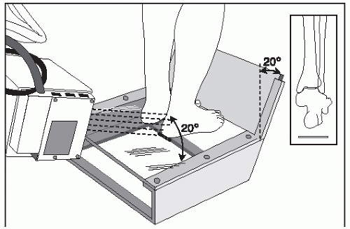 Figure 113.3 Hindfoot alignment (Saltzman) view is obtained with the patient standing on a radiolucent box or platform with the cassette angled 20 degrees (see illustration). The x-ray beam is adjusted to be perpendicular to the cassette. The cassette should be large enough to include the entire calcaneus and the distal half of the tibia. (From Paley D, ed. Principles of deformity correction. Berlin, Germany: Springer-Verlag, 2003, with permission.) |
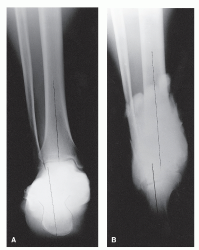 Figure 113.4 A: Hindfoot alignment (Saltzman) view allows visualization of the ankle joint and the relationship of the calcaneus to the tibia. This radiograph is also useful for assessing the amount of lateral translation of the calcaneus. B: Long calcaneal axial view radiograph allows visualization of the subtalar joint and the relationship of the calcaneus to the tibia. This radiograph is also useful for assessing the tuber of the calcaneus. The combination of these two radiographs is valuable for hindfoot and ankle deformity planning. (From Paley D, ed. Principles of deformity correction. Berlin, Germany: Springer-Verlag, 2003, with permission.) |
TIBIA
The mechanical axis of the lower extremity typically passes through or just medial to the center of the knee joint. The normal range of the MAD is 8 ± 8 mm medial (see Fig. 113.6). The anatomic axis of the tibia usually passes though the medial tibial spine. The tibial mechanical axis passes through the center of the knee and ankle joints. The tibial anatomic axis is parallel and just medial to the mechanical axis (Fig. 113.9). In the sagittal plane, the anatomic axis of the tibia (middiaphyseal line) intersects the tibial plateau joint orientation line one-fifth the distance from the anterior surface of the tibia and crosses the center of the ankle.
In the frontal plane, the joint orientation angles are the medial proximal tibial angle (MPTA), with a normal value of 87.5 ± 2.5 degrees, and the lateral distal tibial angle (LDTA), with a normal value of 89 ± 3 degrees. In the sagittal plane, the joint orientation angles are the posterior proximal tibial angle (PPTA), with a normal value of 81 ± 3 degrees, and the anterior distal tibial angle (ADTA), with a normal value of 80 ± 2 degrees (see Fig. 113.1).
The ankle joint orientation is in slight valgus to the tibial shaft. In the frontal plane, during the midstance phase of gait (single support time), the tibia is oriented in 3 degrees of adduction, thereby allowing the tibial plateau to become horizontal (87 degrees + 3 degrees = 90 degrees). Similarly, the ankle joint slight valgus makes the ankle parallel to the knee joint and therefore parallel to the ground during singlelimb stance. In the sagittal plane, during the midstance phase of gait (maximum loading), the tibia is oriented 10 degrees inclined forward toward the ground (knee flexed 20 degrees) and the ankle is in 10 degrees of dorsiflexion. Therefore, the normally sloped tibial plateau and tibial plafond become horizontal during maximum loading, distributing the forces more evenly in an axial direction, which minimizes shear while maximizing the surface area of joint contact.
TALUS
The tibiotalar joint, or ankle joint, is congruent in a normal patient without joint line convergence between the dome of the talus and the tibial plafond in the frontal plane. This is unlike the knee joint. With the knee joint, an angle of up to 3 degrees (joint line convergence angle [JLCA]) might exist normally between the tibial plateau and femoral condyles. The shape of the talus in the frontal plane appears square in cross section. The anatomic axis of the tibia intersects the dome of the talus just medial to the bisection (center) of the talar dome (Fig. 113.10). The relationship of the malleoli to the tibia was described by Inman (8) as the talocrural angle, measuring 82 ± 3.6 degrees (Fig. 113.11A). We prefer to measure the plafond malleolar angle because it is independent of any supramalleolar deformity. This angle normally measures 9 ± 4 degrees (Fig. 113.11B). The plafond malleolar angle is a measure of the level of the lateral malleolus relative to the rest of the ankle joint (1).
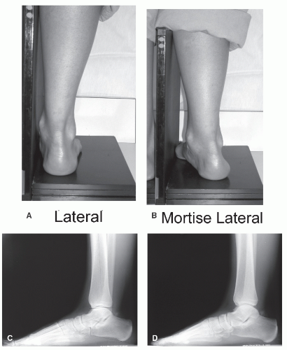 Figure 113.5 Lateral view radiographs are obtained with the foot placed against the cassette. Such positioning produces a radiograph that lacks superimposition of the talar dome and tibial plafond. The mortise lateral view radiograph of the ankle is obtained with the leg internally rotated by 15 degrees, which displaces the heel slightly away from the cassette when positioning. With the mortise lateral view radiograph of the ankle, the two malleoli are overlapped, the medial and lateral aspects of the talar dome are superimposed, and the tibial plafond is seen in maximum profile. The mortise lateral view radiograph provides ease for drawing joint orientation lines, thereby improving accuracy. It is good to compare views that are orthogonal, such as the mortise AP and mortise lateral view radiographs (both are obtained with the leg in 15 degrees of internal rotation). (Copyright 2008, Rubin Institute for Advanced Orthopedics, Sinai Hospital of Baltimore.) |
In the sagittal plane, the talar projection appears circular in shape. Inman (8) described the three-dimensional shape of the talus as a frustum (section of a cone) and discovered that the ankle joint axis (center of rotation of the ankle joint) is not parallel to the joint line in either the frontal or sagittal plane. The ankle joint axis is best approximated as a line running to the tip of the medial malleolus. In the frontal plane, the ankle joint axis is oriented at the talocrural angle. On a lateral view radiograph, the center of rotation of the ankle joint is best approximated at the lateral process of the talus. The middiaphyseal line on the lateral view coincides with the lateral process of the talus. This is a critical reference point to consider when performing surgery to achieve realignment of the hindfoot and ankle. The plantigrade angle is the angle between the anatomic axis of the tibia, perpendicular to the floor, and the sole of the foot when standing. The normal plantigrade angle is 90 degrees (Fig. 113.12).
CALCANEUS
The calcaneal relationships to the talus and tibia are important, especially in frontal plane assessment. The bisection of the calcaneus is parallel to the anatomic axis of the tibia. The center of the heel is approximately 5 to 10 mm lateral to the anatomic axis of the tibia (Fig. 113.13). The hindfoot alignment (Saltzman view) radiograph allows for visualization of the ankle joint and relationship of the calcaneus and tibia. This view also provides assessment of the lateral translation of the calcaneus in relation
to the tibia (10 mm). The long calcaneal axial view radiograph allows visualization of the subtalar joint and shows the positional relationship of the calcaneus and tibia. The shape of the calcaneus also can be assessed for osseous varus. The posterior and middle facets of the subtalar joint are stepped; the middle facet (sustentaculum tali) is more proximal and medial. The lateral translation of the heel to the tibia is critical for normal gait and
locomotion. The ground reaction vector (GRV) originates at the plantar lateral portion of the foot and extends through the anterolateral aspect of the tibial plafond (Fig. 113.14).
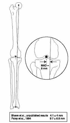 Figure 113.6 Mechanical axis deviation (MAD) is the perpendicular distance between the mechanical axis of the lower extremity (center of femoral head to center of ankle) and the center of the knee joint. The mechanical axis line normally passes 8 mm medial to the center of the knee. (From Paley D, ed. Principles of deformity correction. Berlin, Germany: Springer-Verlag, 2003, with permission.) |
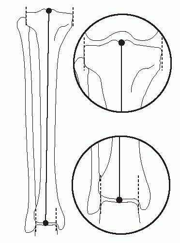 Figure 113.7 Mechanical axis line of the tibia is drawn between the center of the knee and ankle. (From Paley D, ed. Principles of deformity correction. Berlin, Germany: Springer-Verlag, 2003, with permission.) |
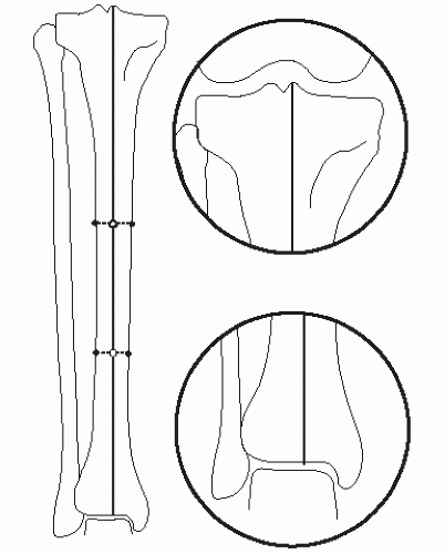 Figure 113.8 Anatomic axis line of the tibia is drawn as a middiaphyseal line of the tibia. (From Paley D, ed. Principles of deformity correction. Berlin, Germany: Springer-Verlag, 2003, with permission.) |
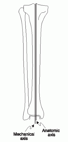 Figure 113.9 Anatomic and mechanical axis lines of the tibia are parallel. (From Paley D, ed. Principles of deformity correction. Berlin, Germany: Springer-Verlag, 2003, with permission.)
Related posts:Stay updated, free articles. Join our Telegram channel
Full access? Get Clinical Tree
 Get Clinical Tree app for offline access

|
