Technical Considerations 
MR imaging is the method of choice for the detection of internal derangements of the various soft tissue structures of joints. Meticulous attention and correct application of various pulse sequences and MR techniques is essential for achieving optimal quality imaging. The latter is important for superior depiction of the bony and soft tissue structures of the joints and related para-articular regions. Ideally, examinations should be directed based on clinical information from the referring clinicians and prescribed by the protocoling radiologist, with active involvement of the performing technologist, as well as engagement of the patient and interpreting radiologist, all participating as a team to obtain the best imaging quality. This chapter presents the MR imaging techniques and available pulse sequences and highlights their advantages and limitations, along with a guide on how to build different musculoskeletal protocols.
 HUMAN CONSIDERATIONS
Referring Physician
Close interaction between the referring clinician(s) and the radiologist is important for protocol prescription and correct interpretation of imaging findings. Clinicians should be informed regarding the technical limitations of MR imaging (e.g., larger the anatomy to be covered, the longer the overall examination will take, consequently the resolution could be degraded). The protocols vary depending upon whether the clinical question is injury, pain or other nonspecific symptoms (ortho protocol), infection or inflammation (infection protocol), tumor (mass protocol), labrum, full-thickness rotator cuff tear or loose body (MR arthrogram), slow-flow or high-flow vascular malformation (vascular malformation protocol), cartilage evaluation (cartilage protocol), myositis or myopathy (myositis protocol), metal prosthesis related complications (metal protocol), and peripheral nerve evaluation (MR neurography). The use of gadolinium-based contrast agents is essential in MR arthrograms, as well as in cases of suspected infection, inflammation, vascular malformation, and mass lesion. Image manipulation (postprocessing) becomes important whenever high-end imaging is performed (e.g., with 3D imaging, functional cartilage imaging, and neurography). Although such high-end imaging may or may not be useful for the radiologist’s routine interpretation, the reconstructed longitudinal images, color maps, curved and maximum intensity projections (MIPs) serve as useful preoperative guides for the surgeons. In addition, buy-in of the subspecialist clinicians is also important when one performs such imaging on their patients since high-resolution or 3D imaging demands more imaging time, produces coarser images and lots of thin slices that have the potential to increase the evaluation time. On the other hand, 3D imaging potentially increases the diagnostic confidence of the radiologist since smaller labroligamentous structures and thinner cartilage can be easily evaluated on a series of small sections and at any desired oblique plane. Finally, angular or rotational measurements can be obtained on thicker slab MIPs generated from such scans similar to cross-sectional CT examination (Fig. 1).
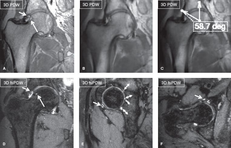
Fig. 1: Three-dimensional hip imaging in femoroacetabular impingement. Coronal non–fat-suppressed 3D (A), thick slab (B, C), and multiplanar reconstructions from fat-suppressed 3D; (D–F) show fibrocystic change of the right femoral head and neck junction (long arrows), chondrolabral separations (short arrows), and lateral center angle measurement in thick slab MIP (C). Notice elegant depiction of multiple cartilage fissures of the posterior acetabulum (double head arrows in E) in otherwise coarser looking image due to 0.65-mm isotropic resolution.
Patient Coaching
The technologist plays an important role in patient coaching for successful performance of the examination. The patient should fill out a form with most relevant acute or chronic complaints and history of prior regional surgery. Ideally, a marker should be placed at the most symptomatic painful, injured or palpable site, and the patient should be asked to remain still during the image acquisition, as well as to breathe normally. The extremity should be well padded for comfort and the coil tightly wrapped around it to restrict motion during the examination. If there is motion during the study, the technologist should stop the scan, talk to the patient to make him/her comfortable, instruct him/her not to move, and repeat the degraded sequence(s). One could give intravenous glucagon to decrease bowel peristalsis-related artifacts during lumbosacral plexus imaging; however, it is important to remember the contraindications (such as glaucoma) and also instruct the patient of side effects, such as rebound hypoglycemia.
 TECHNICAL CONSIDERATIONS
Scanner Selection
Since most musculoskeletal soft tissue structures are relatively small, imaging is best performed on 3T scanners to make use of the higher signal-to-noise ratio (SNR) these machines provide. The 3T SNR can be traded as currency for imaging speed or resolution, or both. Higher SNR translates into higher soft tissue contrast and potentially faster imaging while keeping the slice thickness to a minimum, thereby, enhancing the spatial resolution. One should aim at the smallest in-plane resolution, whether imaging is performed on 1.5T or 3T. Signal averages can be used to further improve the SNR but longer scans risk motion blurring. Reducing signal averages (repeat acquisitions aka number of excitations [NEX]/number of signal averages [NSA]) or prudent use of parallel imaging can achieve faster scanning. In larger joints or larger subjects, it might be necessary to use larger voxels to maintain adequate SNR. One could use enhanced (fast) gradient mode to further improve SNR and reduce blurring effects. Imaging on 3T scanners is advantageous in obtaining 3D imaging with spin echo-type contrast, and this leads to fine evaluation of various small structures, such as menisci, cartilage, ligaments, and nerves in multiple arbitrary planes with isotropic resolution (Figs. 2, 3). Three-dimensional imaging is also relatively devoid of pulsation artifacts and produces better fluid contrast, especially using DRIVE (driven equilibrium) pulse. This pulse not only shortens TR and makes acquisition shorter, but it also increases fluid-cartilage interface conspicuity.
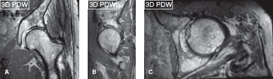
Fig. 2: Three-dimensional hip. Isotropic 0.65-mm coronal acquisition (A) and reconstructed sagittal (B) and axial (C) scans on a 3T scanner (Achieva, Philips Healthcare, Best, Netherlands).
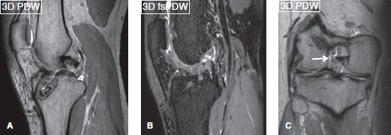
Fig. 3: Three-dimensional knee. Isotropic 0.65-mm sagittal acquisitions (A, B) and reconstructed coronal (C) scans on a 3T scanner (Achieva, Philips healthcare, Best, Netherlands) showing ACL graft reconstruction with midportion disruption (arrows).
Nevertheless, the authors encourage the use of 1.5T as well because the latter scanners perform better in patients with metallic material(s) in the region of imaging, in whom 3T is expected to produce artifacts. Three-dimensional imaging on 1.5T scanners is usually not isotropic due to time limitations. The latter scanners produce finer in-plane images whereas off-plane images are frequently degraded (Fig. 4). Modern 1.5T scanners, however, perform nearly similar to older generation 3T scanners if joint-specific coils are used that possess multiple channels and superior gradient strength. To reduce inhomogeneity in off-center areas, such as shoulder and wrist, one may employ higher second-order shimming (pencil beam [PB]-Volume, Philips) for better field homogeneity, in order to obtain more uniform fat suppression. Higher-field strength, newer coils, faster computer processing and pulse sequences have allowed reduction in the voxel sizes at 3T by a factor of 2 to 5 versus the comparable 1.5T protocols. Similarly, for MR neurography, one should ideally use 3T imaging for multiplanar depiction of peripheral nerves. Two-dimensional imaging is not a problem, but fat-suppressed (fs) 3D imaging is frequently limited on 1.5T scanners (Fig. 5).
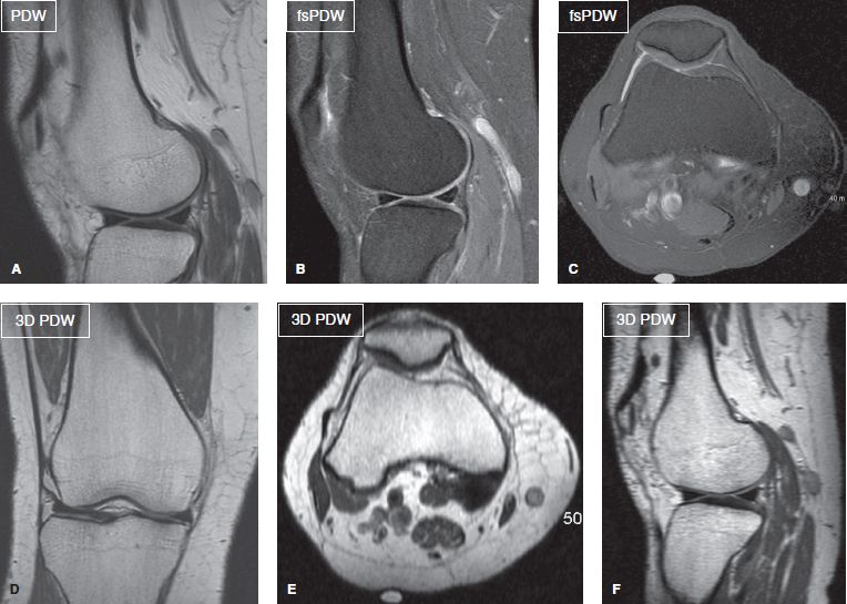
Fig. 4: Two-dimensional versus 3D imaging on 1.5T MR scanner. Sagittal (A, B) and axial (C) 2D images with high in-plane resolution (0.4 to 0.5 mm). Corresponding nonisotropic coronal acquired 3D image (D) shows high (0.65 mm) resolution while the axial and sagittal (off-plane reconstruction) images (E, F) are degraded.
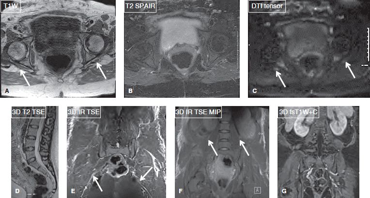
Fig. 5: MR neurography at 1.5T. Axial images (A–C), sagittal (D), and coronal (E–G) images in a case of traction neuropathies of right sciatic and femoral nerves (arrows). Notice good axial demonstration, however fat-suppressed 3D long-axis imaging is limited.
Coil Selection
Dedicated multichannel joint coils should be used in the extremities in an attempt to attain the best signal on average-sized patients. For larger-sized patients, large flex coils or torso array coils be more beneficial, especially in off-center areas of the magnet. The technologist should not try to wrap the joint and extremity together and image them both in the same field of view (FOV) because this results in low-quality images with a large blank space around the region of interest (ROI). One should aim at less than 20% blank (air) space around the extremity (Fig. 6). The technologist may have to do phase oversampling to avoid wraparound artifacts and encompass the small FOV imaging. For pelvis, lumbosacral or brachial plexus imaging, spine array coils can be combined with torso array coils on the front of the patient, or if the scanner does not allow that particular combo, a torso coil/cardiovascular coil with front and back coverage may be used to obtain the needed SNR, better signal homogeneity, and uniform fat suppression.
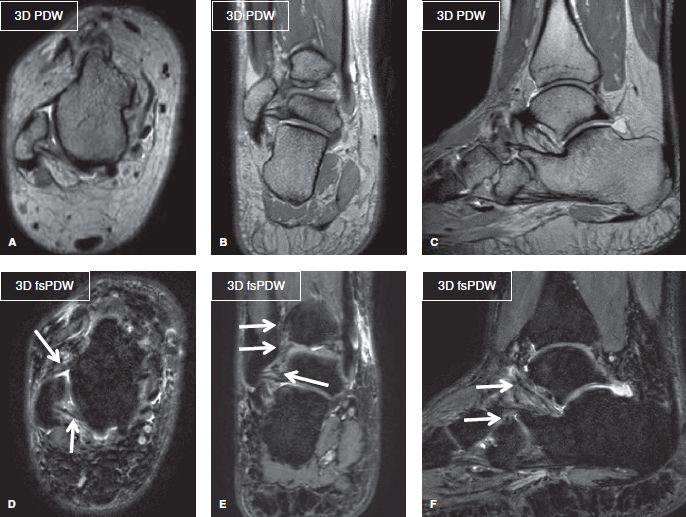
Fig. 6: Three-dimensional isotropic ankle imaging. Multiplanar 3D reformats (A–F) from 0.65-mm isotropic ankle images. Notice the tight field of view with less than 20% blank (air) space around this rather larger ankle. Images re coarse-looking but provide fine demonstration of the ankle ligaments (arrows).
Controlling Phase Wrap
While it is important to keep the FOV small (less than 10–14 cm for most joint protocols) to obtain good spatial resolution, wrap-around or fold-over artifacts may degrade the imaging. Certain strategies may be used to avoid phase wrap.
1. Use a larger enough FOV, but this may require zooming during image review to focus on the anatomy of interest and may leave excess blank (air) space around the ROI.
2. Use fold-over suppression (Philips) or phase oversampling (Siemens).
3. Employ conventional methods of saturation bands to eliminate signal from adjacent anatomy that is vulnerable to motion (e.g., lungs in arm imaging).
4. Use REST slabs as an alternative to oversampling for reducing the total scan time.
5. Use phase-encoding gradients in the sagittal plane for coronal anatomy (e.g., to avoid arms fold-over in the desired abdominal ROI).
K-space Profiling and Bandwidth
Asymmetric k-space profile ordering is used to reduce scan time by about 30% in proton density-weighted (PDW) and T1-weighted (T1W) images while minimizing blurring as compared to conventional k-space profiling (linear or centric).
 Asymmetric fast spin echo (FSE) scans permit independent specification of echo time (TE), echo spacing (ES), and echo train length (ETL or turbo factor).
 In general, shot length (ETL × ES) should not exceed 4 × TE for PDW images. For T1W images, shot length should be limited to 60 ms for good results.
 ES in most protocols is set at 8 to 9 ms (<8 in metal protocols and diffusion imaging), balancing the shot length against the imaging bandwidth.
 If a different profile order is used (such as linear or centric), reduce the ETL on these protocols by about 30%. Scan times will increase proportionately (Goumas, 2012).
Bandwidth in kHz (Siemens) versus direct specification of water-fat shift (WFS) in pixels (Philips) is an important parameter and measure of potential ringing artifact and impact on SNR independent of field strength, pixel size, and FOV.
 For musculoskeletal imaging, keep WFS between 1 and 2.5 pixels to avoid obscuring pathology (0.5 to 1.5 mm shift), <1.5 pixels for metal protocols (Fig. 7).
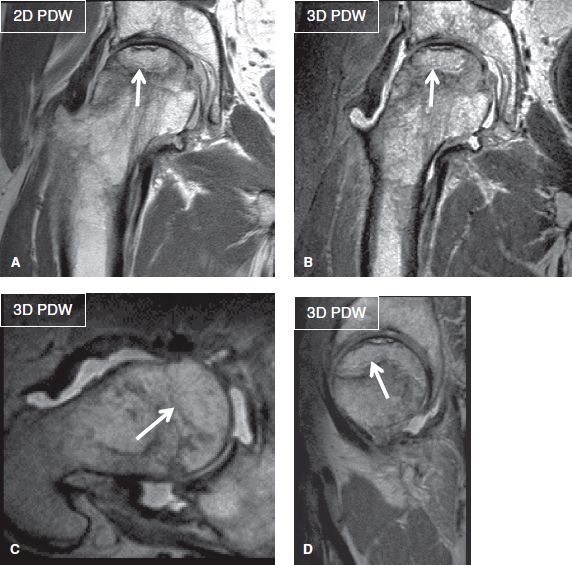
Fig. 7: Tight water-fat shift. Coronal 2D (A) and corresponding isotropic 3D (B–D) images (TR/TE—1879/40 milliseconds) show high resolution (acquired 0.4 mm in-plane on 2D and 0.7 mm isotropic on 3D) with tight water-fat shift (1.37 pixel; bandwidth 317 Hz) and echo spacing (5.7). Notice femoral head AVN with subchondral fracture (arrows).
 Reducing WFS (increasing BW) reduces ES, which in turn reduces turbo spine echo (TSE) length, as well as image blurring.
 Reducing WFS (increasing BW) also reduces SNR.
 Conversion factors to remember (Goumas, 2012):
3T: BW (kHz) = 0.22 kHz × freq matrix/WFS pixels
1.5T: BW (kHz) = 0.11 kHz × freq matrix/WFS pixels
2D Imaging Pulse Sequences
A variety of 2D imaging pulse sequences are available for high-resolution musculoskeletal imaging resulting in different contrasts.
T1W Imaging
Commonly used sequences include T1W FSE or T1W TSE, T1W fluid-attenuated inversion recovery (T1W FLAIR) and T1W GRE. General advantages of T1W imaging include excellent demonstration of musculoskeletal anatomy with non-suppressed fat contrast, in terms of both bony morphology and alignment. T1W imaging is great for depicting subluxation, malalignment, bony spurs, and osteophytes. Since T2-weighted (T2W) images are very sensitive in identifying pathology (which is usually bright on these images), T1W imaging is very helpful in characterizing them. It characterizes both types of bony lesions that produce substantial T1 darkening in the marrow (fracture, infection, osteonecrosis, tumor infiltration, hemosiderin deposition, subchondral sclerosis, and cysts) and the lesions that produce minimal or no significant darkening in the marrow (red marrow, reactive edema, and disuse osteopenia). T1W images are also helpful in characterizing soft tissue lesions (e.g., most lesions are T1 dark whereas some are bright, such as hemorrhage, fat, melanin, calcification, and minerals).
T1W SE or T1W FLAIR sequences are useful in all musculoskeletal protocols. In routine “ortho” protocols, marrow evaluation is limited if T1W or chemical shift imaging (CSI) is not added (discussed below). T1W GRE is useful for scout imaging (for planning), in- and out-of-phase (for marrow evaluation), MR-guided intervention (MR fluoroscopy), kinematic joint imaging, MR angiography (MRAng), ultra-short TE imaging, arterial spin labeling and T1 mapping techniques used in cartilage imaging. MRAng is best obtained with time (temporally) resolved imaging technique using fast GRE T1W pulse sequence with acquisition of mask images and post-contrast serial 8 to 15 seconds thick slab acquisitions over 2 to 3 minutes. These are variably named as TWIST, TREAT, TRICKS, and 4D TRAK by different vendors. The major disadvantage is decreased spatial resolution, but there are many advantages, including decreased gadolinium dose, no need for test bolus, detection of directionality of vascular flow, and acquisition of various phases of vascular, lesional and parenchymal enhancement. With subtraction manipulation, these images can be played in a cine loop for demonstration of various phases of vascular contrast enhancement. fsT1W FSE imaging is useful for 2D pre- and postcontrast imaging whereas fsT1W GRE can be applied for obtaining 3D pre- and postcontrast imaging. Three-dimensional GRE T1W is routine in most post-contrast protocols, and they are variably named by different vendors (VIBE, THRIVE, LAVA, mDixon). fsT1W spin echo-type 3D imaging (VISTA, SPACE) is also available for MR arthrogram (Fig. 8). These sequences potentially detect smaller tears that otherwise may be inapparent at 2D imaging. However, blurring on the images may not be pleasing to the reader.
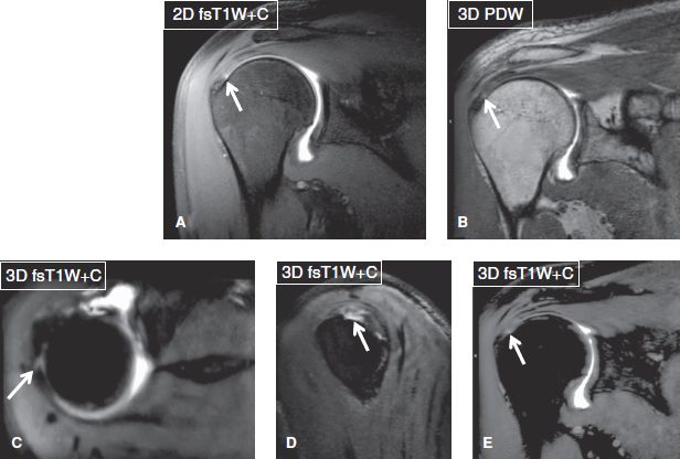
Fig. 8: MR arthrogram: 2D (A, B) versus 3D (C–E) images. Notice small undersurface tear of the rotator cuff (arrows), best seen on multiplanar isotropic 3D images.
PDW Imaging
Commonly used sequences include PDW and fsPDW. General advantages of PDW imaging include highest SNR amongst all available sequences, sharp image resolution, and excellent demonstration of musculoskeletal anatomy and pathology in terms of meniscal, anatomic cartilage, and ligament evaluation (essential for ortho and metal protocols) (Figs. 1–3, 6). Generally, bone marrow evaluation is limited on these ortho protocols if T1W imaging or CSI is not added to the technique (Fig. 9).
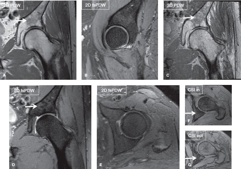
Fig. 9: CSI as part of ortho musculoskeletal (MSK) protocol. Coronal (A, C, D), sagittal (B), and axial (E–G) images show scattered areas of red marrow (arrows), which are brighter than muscles on PDW images. One such area is shown to lose signal on the out-of-phase image (G) relative to the in-phase image (E).
Related posts:


Stay updated, free articles. Join our Telegram channel

Full access? Get Clinical Tree


