Technical Advances in Musculoskeletal Imaging
Hubert Lejay
Betsy A. Holland
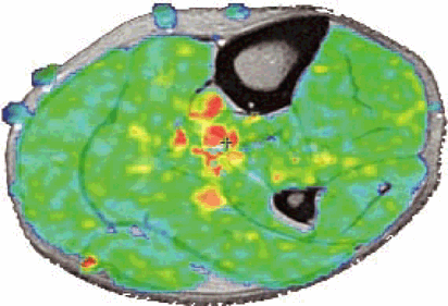
Musculoskeletal MR imaging presents unique technological challenges. Although peripheral joints offer intrinsic rich soft tissue contrast (Fig. 1.1), the anatomy is often complex, with small structures, many of which course in oblique planes. High-resolution imaging of the small-scale anatomy of menisci, labra, carpal bones, and articular cartilage demand 2D multislice sequences with in-plane resolution of at least 0.5 mm (preferably 0.2 to 0.3 mm), with a slice thickness of 1 to 3 mm (Fig. 1.2). The many soft tissue interfaces inherent to musculoskeletal anatomy and morphology also present challenges to successful imaging. Changes in magnetic susceptibility can occur at the interfaces between cartilage, cortical bone, and bone marrow. Therefore, when placed in a magnetic field, these interfaces generate abrupt changes in local magnetic field gradients, creating a faster signal decay due to spin-spin dephasing (T2*). In addition, patients may have metallic prostheses or postsurgical metallic debris, which produce additional magnetic susceptibility artifacts (Fig. 1.3). Fat, both in subcutaneous tissues and bone mar row, may also present imaging problems. The hyperintense signal of fat on conventional T1-weighted and proton density-weighted sequences can ob scure underlying pathology. In addition, at fat-water in terfaces, there may be a chemical shift artifact that degrades images. Finally, musculoskeletal soft tis sues have relatively short T2 relaxation times due to their highly organized molecular structure in fiber networks. The T2 relaxation of tendons and ligaments is in the range of a few milliseconds (msec); that of cartilage is 10 to 30 msec. These structures also show a significant variation in T2 relaxation based on their physical orientation to the main magnetic field. When fibers form an angle of 55 degrees from the main magnetic field, T2 time be comes longer, generating a hyperintense signal (the magic angle effect; Fig. 1.4).
Solutions to these imaging problems are being addressed through a variety of approaches, including innovations in data acquisition schemes, MR pulse sequences, and hardware.
New Data Acquisition Schemes
Pearls and Pitfalls
Data Acquisition Schemes
Conventional data acquisition schemes
Acquisition of k-space data in sequential parallel lines in a 2D or 3D Cartesian grid
Imaging with a single RF coil, resulting in sequential acquisi tion of data
Alternative methods of sampling k-space (less subject to motion, chemical shift, and pulsation artifacts)
Navigation of k-space using spiral, radial, or PROPELLER trajectories
Oversampling of central k-space, which contains information about gross structure and image contrast
Parallel imaging (simultaneous image acquisition)
Imaging with an array of RF coils, resulting in the simultaneous acquisition of data over several points
Fewer gradient steps are necessary because spatial information is encoded by the distribution of coils as well as by spatial encoding from gradients.
Scan acceleration of 2 to 4 times is possible.
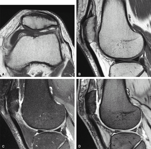 FIGURE 1.1 ● Routine knee examination. (A) Axial T1-weighted 2D fast/turbo spin-echo image. (B) Sagittal proton density-weighted image. (C) Sagittal proton density-weighted image with chemical fat suppression. (D) Gradient-echo image. |
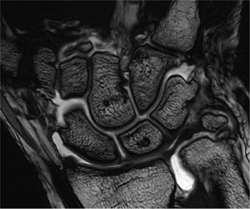 FIGURE 1.2 ● High-resolution wrist arthrography. 3D-FIESTA sequence (steady state free precession), TR 9.2 msec, TE 3.1 msec, voxel size 0.26 × 0.28 × 1.2 mm, acquisition time 3 minutes, 28 seconds. |
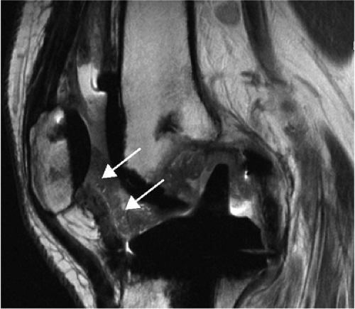 FIGURE 1.3 ● Total knee arthroplasty with synovitis (arrows). Acquired at 1.5 T. Use of an RBW of 83.3 kHz results in limited metallic susceptibility artifact. |
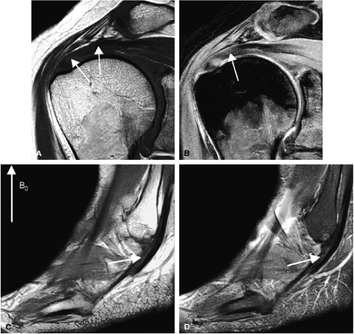 FIGURE 1.4 ● Magic angle effect (arrows). (A, B) Magic angle is seen in a shoulder examination using a short TE (A) and long TE (B). Magic angle in an ankle examination without (C) and with (D) FatSat. |
Conventional MR studies are acquired by the serial application of encoding gradients across the field of view (FOV) using a single radiofrequency (RF) coil. The resulting signals received by the RF coil provide data corresponding to the spatial frequency or Fourier components of the object being imaged. Each component of the data, one of a large number of sinusoidal intensity oscillations with specific spatial frequencies, is associated with a particular point in k-space. The central region of k-space, consisting of low-spatial-frequency data, contains information about the gross structure and contrast of an image, most of the information required to produce an MR image. The peripheral portion of k-space, consisting of high-spatial-frequency data, contains information about image detail. Data is usually acquired in a 2D or 3D Cartesian rectangular grid in k-space, moving from one end of k-space to the other, collecting data in sequential parallel lines. An additional line of k-space data in the frequency-encoding direction is serially collected during each acquisition, while sequential lines in the phase-encoding direction are acquired at regular intervals.
Alternative methods of sampling or navigating k-space and of acquiring data are being developed and have the potential to improve both the speed and accuracy of MR musculoskeletal imaging. Two of these techniques, PROPELLER imaging and parallel imaging, are discussed below.
PROPELLER (Radial Acquisition)
Sampling data using the conventional Cartesian technique, with line-by-line sampling of k-space, results in artifacts associated with phase and frequency encoding. Chemical shift results in artifact in the frequency-encoded direction, and motion results in artifact in the phase-encoded direction. Other methods that sample the central and peripheral regions of k-space simultaneously, rather than sequentially in a grid, can reduce these artifacts. Other patterns or trajectories of k-space sampling include radial, spiral, and PROPELLER imaging.
PROPELLER fast spin-echo 1 is a radial k-space filling technique. A range of ultra-low-resolution images are acquired, one per repetition time, with as many phase-encoding steps as echoes in the echo train length (ETL). Each of these scans corresponds to a different rotational direction within the scan plane. Since the data are collected in a series of rectangular strips, serially rotating around central k-space, central k-space is repeatedly sampled. The data set looks like a freeze-frame photograph of a rotating propeller, with the hub located in the center of k-space. Data reconstruction then combines these different data collections in the image domain and corrects or even rejects (based on relative phase information) data acquisitions that are degraded by motion. The resulting final image is relatively free of motion artifact. Also, of particular benefit to musculoskeletal imaging, radial scanning produces fully isotropic in-plane resolution with no frequency and phase direction. Consequently, chemical shift and pulsatile flow artifacts are diffused across the whole image plane, so these artifacts are far less discernible than with Cartesian imaging (Fig. 1.5).
Parallel Imaging
Imaging with a single RF coil, with sequential acquisition of data, point by point, limits the speed with which an MR scan can be performed. Constraints include limits on the amount of soft tissue RF power deposition over a short period of time and limits on the maximal rate of gradient switching of coils. The conventional solutions to these speed limitations, including 1 NEX or fractional NEX imaging and the use of partial phase FOV and shorter repetition times (TRs), have been exhausted. In parallel MR imaging, however, images are acquired with an array of RF coils and the simultaneous acquisition of data over several points, dramatically accelerating imaging times without compromising spatial resolution.2
In parallel imaging, a set or array of RF coils is distributed along the structure to be imaged. The spatial information from this distribution of coils can be used, in addition to spatial encoding from gradients, to generate data for MR image reconstruction (Fig. 1.6). Consequently, fewer gradient steps need be performed and the data set can be undersampled. To maintain spatial resolution, a reduced FOV is used. However, because the data are undersampled in the phase direction, anatomy aliasing or fold-over occurs. Since each of the coils in the array experiences this aliasing differently, based on its coil sensitivity pattern, image reconstruction algorithms, which combine the data from all the coils, can produce an unaliased image similar in appearance to an image acquired from a fully sampled data set. The fold-over signals are “unfolded” using the spatial information from each coil element contributing to the signal in each voxel.
Parallel imaging is capable of scan time reductions, also called “acceleration,” by a factor of 2 to 4 (and experimentally of up to 10). The consequence, however, is a reduction in the signal-to-noise ratio (SNR). The effects on SNR in an
accelerated scan (SNR ASSET) are illustrated in the following equation:
accelerated scan (SNR ASSET) are illustrated in the following equation:
in which R is the acceleration factor and g is the geometry factor. The geometry factor is noise, which may be amplified by coil design, the reconstruction algorithm, and certain electromagnetic field fundamentals. An array of coils, optimized for accelerated imaging (ASSET/SENSE), has a g-factor of approximately 1 and does not contribute significantly to the loss in SNR with acceleration. Possible residual aliasing in the phase direction may also degrade image quality.
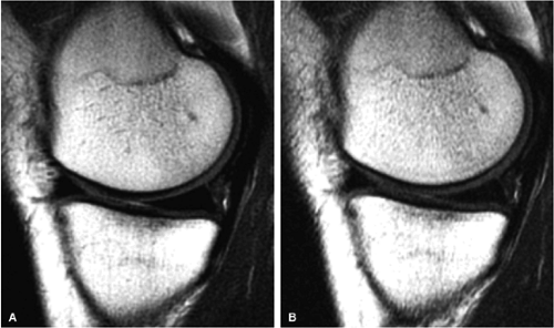 FIGURE 1.5 ● (A) PROPELLER fast spin-echo with a 480 × 480 matrix. (B) Conventional 2D fast spin-echo with 480 × 384 matrix. Scan times were identical. Note an apparent SNR gain in (A) as well as better delineation of cartilage and menisci. |
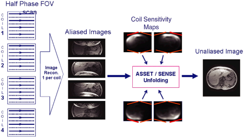 FIGURE 1.6 ● Example of parallel imaging: ASSET/SENSE with acceleration × 2. Half of the raw data are acquired, resulting in half the scan time. SMASH/GRAPPA techniques work in the k-space domain instead of the image domain. |
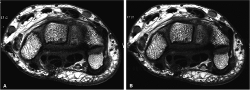 FIGURE 1.7 ● SENSE/ASSET acceleration × 2 with an eight-channel wrist array coil. Axial 2D fast spin-echo (TR 700, TE 16, ETL 2, slice thickness 2 mm, FOV 10 cm, 384 × 320 matrix, 15 slices). With ASSEST × 2 (A), scan time was 58 seconds. Without ASSET (B), scan time was 1 minute 54 seconds. The SNR reduction with ASSET is minimized due to the optimal coil g-factor. |
Despite these SNR limitations, parallel imaging can provide improved image quality and spatial resolution using a shortened scan time. For example, wrist imaging is best performed in the difficult-to-maintain “Superman” position, with the surface coil as close to the magnet isocenter as possible. Parallel imaging, with a multichannel coil, can produce a diagnostic wrist study at the rate of 2 minutes per series, or 10 minutes for a complete scan (Fig. 1.7), compared with conventional scan times of 30 minutes.
MR Imaging Protocols
Musculoskeletal imaging protocols were initially dominated by conventional spin-echo and gradient-echo imaging. Conventional spin-echo sequences generate images with excellent soft tissue contrast and perform well in imaging structures with high magnetic susceptibility; however, the sequences are relatively time-consuming. Gradient-echo sequences can dramatically decrease scan times, but some applications, such as echo radial-oblique long axis sequences, which may produce false-positive results in the evaluation of meniscal tears, have proved unreliable. For general peripheral joint imaging, sequences that can be performed quickly (but produce spin echo-like soft tissue contrast) and fat-suppression sequences with sufficient T1 weighting to be sensitive to gadolinium contrast enhancement are essential. For more specific applications, such as cartilage mapping, more complex protocols are needed. A plethora of pulse sequences are currently available, and more are being developed to address these imaging requirements. A few of the more important protocols for musculoskeletal applications are discussed below.
Fast (Turbo) Spin-Echo Imaging
Pearls and Pitfalls
Fast (Turbo) Spin-Echo Imaging
A series of spin echoes fill lines of k-space, reducing scan time.
The number of echoes in the series is the echo train length (ETL), usually 3 to 16.
The time between the echoes in the echo train is the echo train space (ETS), usually 4 to 10 msec.
The full time to collect the echoes is the sum of the ETL and ETS between each echo.
Signal loss from T2 relaxation occurs progressively during the echo train. Therefore, tissues with a short T2 relaxation do not contribute data to the late echoes that encode for spatial resolution, and image blurring results.
Since the T2 relaxation time of most musculoskeletal tissues is relatively short, a short echo space minimizes image blur.
Decreasing echo space is best accomplished by increasing the receive bandwidth (RBW).
Fast spin-echo sequences produces images similar in appearance and content to conventional spin-echo sequences in a fraction of the time. The advent of spin-echo train acquisition
techniques in the early 1990s3 revolutionized MR imaging by allowing the collection of spin-echo data in less time than any of the then currently available gradient-echo or spin-echo sequences. In conventional spin-echo imaging, each echo generates one image. In fast spin-echo imaging, a series of spin echoes, called the echo train, fill lines of k-space, thereby reducing scan time. The series of spin echoes are generated by the use of 180-degree refocusing RF pulses at regular intervals. After each 180-degree pulse, an echo signal is collected that fills a different line of k-space (Fig. 1.8). The images are then reconstructed from the data collected over many echo times (TEs). Scan times are reduced by a factor equal to the number of echoes, the ETL. ETLs vary from 3 to 16. The time between the echoes in the echo train is called the echo train space (ETS) and is generally 4 to 10 msec.
techniques in the early 1990s3 revolutionized MR imaging by allowing the collection of spin-echo data in less time than any of the then currently available gradient-echo or spin-echo sequences. In conventional spin-echo imaging, each echo generates one image. In fast spin-echo imaging, a series of spin echoes, called the echo train, fill lines of k-space, thereby reducing scan time. The series of spin echoes are generated by the use of 180-degree refocusing RF pulses at regular intervals. After each 180-degree pulse, an echo signal is collected that fills a different line of k-space (Fig. 1.8). The images are then reconstructed from the data collected over many echo times (TEs). Scan times are reduced by a factor equal to the number of echoes, the ETL. ETLs vary from 3 to 16. The time between the echoes in the echo train is called the echo train space (ETS) and is generally 4 to 10 msec.
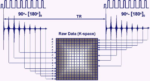 FIGURE 1.8 ● Fast or turbo spin-echo. After each 180-degree refocusing pulse, an echo signal is collected and fills a different k-space line. This accelerates data collection by a factor equal to the ETL. |
Signal loss from T2 relaxation occurs progressively during the course of the echo train. The longer the echo train, the more T2 relaxation occurs, with consequent image blurring. In musculoskeletal MR, T2 values range from a few milliseconds for tendons and ligaments to 35 to 40 msec for articular cartilage. As illustrated in Figure 1.9, with application of an echo spacing that is too large and a short TE, only
the early echoes of the echo train are seen in structures with a T2 of 10 msec. For tissues with a long T2 (100 msec for instance), all the echoes in the train are seen. The early echoes in the echo train contribute information from central k-space and improve SNR and produce image contrast. The later echoes in the train, with information from peripheral k-space, improve spatial resolution. Consequently, blurring occurs if a long echo train or echo spacing is used for tissues with a short T2 relaxation time, since the raw data from the late echoes that encode high-spatial-frequency details are missing. To minimize blurring when imaging tissues with a short T2 relaxation time, shortening of the ETL and/or the ETS may be required.
the early echoes of the echo train are seen in structures with a T2 of 10 msec. For tissues with a long T2 (100 msec for instance), all the echoes in the train are seen. The early echoes in the echo train contribute information from central k-space and improve SNR and produce image contrast. The later echoes in the train, with information from peripheral k-space, improve spatial resolution. Consequently, blurring occurs if a long echo train or echo spacing is used for tissues with a short T2 relaxation time, since the raw data from the late echoes that encode high-spatial-frequency details are missing. To minimize blurring when imaging tissues with a short T2 relaxation time, shortening of the ETL and/or the ETS may be required.
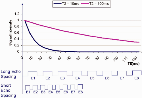 FIGURE 1.9 ● Short T2 relaxation times and echo train in fast or turbo spin-echo imaging. If echo spacing is too long, the high spatial resolution is missing from the late echoes, resulting in increased blurring. |
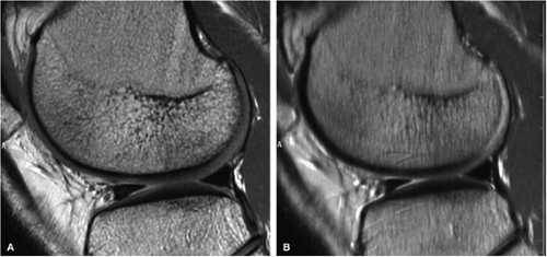 FIGURE 1.10 ● Effect of RBW on fast spin-echo. Note (A) the chemical-shift effect (arrows) on the bone-cartilage interface and (B) the increased blurring due to the longer echo spacing with ± 7 kHz. |
Unfortunately, shortening the ETL to improve images of tissues with a short T2 relaxation time adversely affects the potential benefits of reduction in scan times. An alternative solution for decreasing the time needed to perform the echo train, shortening echo spacing, is affected by two other parameters, the frequency matrix size and the receive bandwidth (RBW), both of which control the signal readout time.
Whereas echo spacing changes proportionally with changes in the frequency matrix, it changes inversely with changes in the receive bandwidth. For example, doubling the frequency matrix from 256 to 512 doubles the signal readout time and the echo space. On the other hand, doubling the receive bandwidth from ±16 kHz to ±32 kHz cuts both the readout time and echo spacing in half. Since the frequency matrix must remain as high as possible to achieve the desired spatial resolution, manipulation of the RBW is a critical scan parameter in musculoskeletal imaging (Fig. 1.10).
The RBW affects not only the echo spacing, and secondarily image blurring, but also chemical shift, signal-to-noise, and gradient requirements. The high RBWs that promote short echo spacing result in decreased chemical shift. The chemical shift effect is the frequency shift between fat and water components (220 Hz at 1.5 T), which translates into a spatial shift often visible on images. It can be expressed in number of pixels (Fig. 1.11). However, higher RBWs also decrease signal-to-noise (Fig. 1.12). When the RBW is increased, more noise is collected for the same amount of signal, degrading the SNR. Furthermore, using a very high RBW demands more gradient strength from the system. This may place hardware limitations on the simultaneous manipulation of other parameters, such as FOV and slice thickness, which also make demands on the gradients.
Table 1.1 summarizes the effects of changing RBW and the frequency matrix on image quality. The areas shown in red indicate degradation of image quality; those in green indicate image quality improvement.
TABLE 1.1 ● Effects of Increasing Receiver Bandwidth and Frequency Matrix on Fast Spin-Echo Performance | |||||||||||||||
|---|---|---|---|---|---|---|---|---|---|---|---|---|---|---|---|
|
Fat-Suppression Techniques
Pearls and Pitfalls
Fat-Suppression Techniques
STIR imagingRelated posts:

Stay updated, free articles. Join our Telegram channel

Full access? Get Clinical Tree


