Fig. 16.1
A view of the right knee joint from above after removal of the right femur. Note the three layers of the lateral side and the division of the posterior part of the capsule (layer III) into deep and superficial laminae which are separated by the lateral inferior genicular vessels. (From [16]. Reprinted with permission from JBJS/Rockwater Inc.)
Biomechanically, the LCL is the primary static stabilizer to varus opening from 0° to 30° of knee flexion [19]. The perplexing history of the PFL and contributions to posterolateral stability were detailed by Maynard in 1996 revealing it as a static stabilizer of the posterolateral aspect of the knee that resists varus, external tibial rotation, and posterior translation [20]. Finally, the popliteus tendon is assumed to be a dynamic stabilizer of posterolateral knee with variable muscle activation characteristics [21].
Combined injuries to the PCL and PLC lead to altered stability of the knee in posterior translation and rotation. Cadaver investigations that sequentially sectioned components of the PCL and PLC have demonstrated that the PCL is the principal restraint to posterior translation, but restricts, in combination with the PLC, varus rotation and external tibial rotation [10, 22]. These experiments led the way for biomechanical studies that questioned the influence of PLC deficiency on a PCL graft. LaPrade et al. demonstrated that significant force increases occurred in a PCL graft after sectioning of posterolateral structures and recommended concurrent reconstruction to decrease risk of graft failure [23]. Furthermore, Sekiya et al. demonstrated that combined reconstruction of a double-bundle PCL and PLC can restore knee kinematics to a state near intact ligaments [24]. Subsequent experiments by Apsingi et al. demonstrated that a double-bundle PCL graft along with a PLC reconstruction was unnecessary to restore posterior drawer, external rotation, and varus laxity to normal [25]. Unfortunately, agreement is lacking on graft type or technique with either PCL or PLC to recommend one reconstruction over another.
Initial Evaluation and Management
Although knee dislocations are uncommon injuries with a reported incidence of 0.2–2 % of all orthopedic injuries, the severity of injury presents multiple challenges to treatment [26]. A systematic approach to management of knee dislocations and their sequelae may avoid missed injuries and devastating complications [27]. The initial encounter with a patient with a PCL and lateral-sided injury may occur after a high-impact injury such as motor-vehicle collision, motorcycle collision, motor–pedestrian collision, fall from height or sporting injury, but it may also occur after a low-impact ground level fall, especially in obese patients. By definition, multiligament knee injuries are high-energy injuries, but may occur via high, low, or ultralow velocity mechanisms. If the encounter occurs in the trauma bay or on the playing field, Advanced Trauma Life Support (ATLS) protocol should be followed. As with any initial patient encounter, a thorough history of the accident will yield information as to the mechanism of injury and the velocity of the injury. A large majority of multiple ligament knee injuries stem from knee dislocations that often spontaneously reduce. Because concomitant and potentially devastating neurovascular injuries are common, a high suspicion for a multiple ligament knee injury must always be maintained. It will be important to obtain information from emergency responders, family, and perhaps on-field physicians who may have witnessed the injury and an observation that “the leg was bent the wrong way” [27]. Obvious physical findings of combined sagittal and coronal plane instabilities are diagnostic of polyligamentous injuries.
If a knee dislocation presents unreduced, the first step should be prompt assessment of neurovascular status and immediate reduction, repeat assessment of neurovascular status, and splinting. The common peroneal nerve may be injured in up to 40 % of all knee dislocations; therefore, the neurologic status is a key step in evaluation [28]. Furthermore, the association of arterial injury after knee dislocation with peroneal neuropraxia or permanent peroneal injury can be as high as 62 % [27]. Thus, any nerve palsy warrants a high index of suspicion for vascular injury.
A thorough assessment of vascular status is a vital step in the evaluation of a known knee dislocation or multiple-ligament-injured knee as up to 64 % of patients may have a vascular injury involving either the artery, vein, or both [26]. Although published reports note that serial physical exams (over a 24-h period) and selective arteriography are a safe practice after knee dislocations [29], most authors recommend assessment of ankle–brachial index (ABI) as a diagnostic predictor of vascular injury after knee dislocation [30–32]. Published reports note 95–100 % sensitivity and 97–100 % specificity of ABI in detecting arterial damage in the absence of hard signs (active hemorrhage, expanding hematoma, absent pulse, distal ischemia, or bruit) [30–32]. The senior author (C.J.W.) has previously published an algorithm for diagnosis of vascular injuries in knee dislocations or multiple-ligament-injured knees (Fig. 16.2) [33]. Even after normal ABIs, suspected knee dislocations should be admitted for serial ABIs (every 4–6 h) for 24 h to detect the formation of thrombus resulting from intimal injury or pseudoaneurysm. If the ABI is < 0.9, then either the “gold standard” arteriogram or a computed tomography (CT) angiogram should be obtained to discover the location and extent of vascular injury. Recent evidence demonstrates that CT angiogram may replace arteriogram as the “gold standard” due to availability and lower cost profile [34].
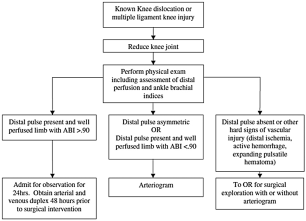

Fig. 16.2
Algorithm for diagnosis of vascular injuries after multiple-liga-ment-injured knees. (From [68]. Reprinted with permission from Springer)
A detailed physical exam will reveal additional objective characteristics of the knee injury. This begins with inspection for effusions, abrasions, ecchymosis, skin dimples, or lacerations. Multiple studies have documented that an acute traumatic knee hemarthrosis often indicates severe structural damage [3, 4, 35–37]. Fanelli found at arthroscopy that PCL injuries occurred in 38–44 % of knees with traumatic hemarthrosis, and of those injuries more than 90 % occurred in the presence of other knee ligament injuries [3, 4]. Following inspection, ROM and ligament stability testing will reveal any limitation to normal motion and uncover suspicions of ligament injury. Ligament stability tests include posterior sag sign, Lachman’s test, posterior drawer test, pivot shift test, reverse pivot shift test, varus recurvatum test, and the dial test [38]. Combined injuries to the PCL and PLC are suggested by a grade III posterior drawer test, increased rotational laxity of the dial test at both 30° and 90° of flexion, positive varus recurvatum test, and a large reverse pivot shift test [8, 38–40].
Radiographs can be very important in the documentation of knee injuries when abnormalities are present, but normal radiographs do not preclude the presence of a severe injury. Findings of capsular avulsions, marginal tibial plateau fractures, large Segond fractures, or proximal fibula fractures may be harbingers of ligamentous injuries [27]. These findings are distinct from typical tibial plateau fractures (which are less commonly associated with neurovascular injuries). Stress radiograph s can be useful to further characterize injuries to the PCL and PLC [40–42]. For chronic injuries, full-length films may uncover limb alignment abnormalities that when corrected may improve sagittal stability [43, 44]. Multiple authors have highlighted the importance of assessing the posterior tibial slope in treating chronic PCL and PLC injuries. Finally, MRI of the injured extremity will confirm suspected ligament damage and provide information regarding additional intraarticular pathology. In addition, MRI can help to indicate the “personality” and energy of the injury, give the surgeon an indication of the location and extent of injured structures (Fig. 16.3).
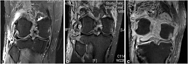

Fig. 16.3
Magnetic resonance images of three injuries that would be classified as KD-3L by the Schenk and Wascher classification system (ACL, PCL, and PLC disruption). a A low-velocity injury. Note the small bony avulsion of the distal fibular collateral ligament from the fibula. There is relatively little surrounding soft tissue edema. b An intermediate-velocity/high-energy injury. There has been significant disruption with bony avulsions of the lateral capsule and fibular collateral ligament, and avulsion of the popliteus tendon. Substantial surrounding soft tissue injury is present. c A high-velocity, extreme-energy injury. Note that lateral anatomic structures are nearly unidentifiable, severe soft tissue edema is present, and gross instability is exemplified by persistent deformity
Postreduction radiographs should demonstrate a concentric reduction. Hinged knee braces locked in extension stabilize the knee with padding placed in the brace to assist with reduction as necessary. After approximately 1 week of immobilization to permit tissues to stabilize, patients begin gentle ROM. Unstable fractures or vascular injuries may warrant external fixation, but otherwise reestablishing ROM of the injured knee should be the goal. In the senior author’s experience, multiligament knee injuries that have undergone extensive immobilization or external fixation not infrequently develop what we term the “FLASCID” knee syndrome (flexion loss with axial, sagittal, and coronal instability after dislocation). This syndrome is characterized by a woody, stiff knee with highly abnormal translation/rotation kinematics at the tibiofemoral articulation. The FLASCID knee is extremely difficult to treat.
There is much debate regarding management of multiple-ligament-injured knees. The Knee Dislocation Study Group reported on many controversies, including nonoperative versus operative treatment, repair versus reconstruction, open versus arthroscopic, early versus late repair, autograft versus allograft, external fixation versus hinged knee bracing, graft fixation, and rehabilitation [45]. Unfortunately, most treatment decisions are based on lower-quality evidence because published high-quality evidence (levels 1 and 2 randomized controlled trials) is scarce. In general, operative treatment is preferred over nonoperative treatment because of improvements in postoperative outcome scores, and reconstruction is preferred over repair [45–48]. Recently, Stannard et al. published a level I randomized controlled trial comparing postoperative treatment of multiple-ligament-injured knees with hinged external fixator versus hinged knee brace [49]. This report noted that reconstructions that were supplemented with a hinged external fixator had fewer ligament reconstruction failures than those supplemented with a hinged knee brace. However, hinged external fixators can be technically demanding to apply and maintain in the hands of surgeons who are unfamiliar with the device. Furthermore, there are often confounding management issues, including medical condition, obesity, concomitant fractures, extensor mechanism disruption, alignment, and social factors that further complicate treatment decisions [50]. Another factor to consider for PCL injuries is its notable healing capacity. In one study, the authors found that more than one third of MRI grade III PCL injuries (complete discontinuity) are clinically stable at the time of repair, and thus the clinical exam of the PCL at the time of surgery should dictate treatment [51].
In general, we advocate an “all-or-none” approach to surgical management of PCL and lateral-sided structures. This recommendation is based on evidence that the PCL and PLC are codominant in controlling posterior translation, external rotation, and varus, so it is ideal to perform concomitant repairs/augmentations/reconstructions so that all repairs are healing in a kinematic environment that is as close to normal as possible. After an acute presentation, the goal is to address injuries in a window from 14 to 21 days after injury. The scheduled delay provides time for an injured capsule to heal, allows the patient to regain knee ROM, and allows for the repair of torn structures before extensive scarring, shortening, and distortion of normal anatomy has taken place. If surgery is not possible within 3 weeks after injury or the patient presents after 3 weeks, it is typical to delay surgery until at least 6 weeks after injury, when the acute inflammatory response has settled, the knee has quieted, and improved ROM has been restored. Prior to delayed reconstruction, a supervised protocol of motion, ice, and compression will help decrease inflammation and “woodiness” of the injured limb. Attempted reconstruction in the maximally inflamed 3–6-week interval after a high-energy injury is often hampered by difficult anatomic dissection secondary to dense fibrotic tissue, protracted ROM recovery, and arthrofibrosis.
Chronic presentation of PCL and PLC injuries can be mired by loss of ROM as a result of extended periods of immobilization. It is crucial to eliminate a bucket-handle meniscus tear, incarcerated cruciate stump, or unreduced tibial eminence fracture as a cause of loss of ROM before instituting a physical therapy program. If a formal course of therapy fails to improve ROM, arthroscopic lysis of adhesions in the suprapatellar pouch, gutters, and the anterior and posterior compartments of the knee as well as manipulation may be required. Delayed reconstructions can be performed to address residual instabilities once the patient has reestablished a more normal knee ROM.
Instruments and Implants
The following instruments/implants can be helpful and should be available:
5-lb bean bag or knee flexion /extension limb positioner (preferred)
Vessel loops (to identify/protect the peroneal nerve)
Retractors (Weitlaner, Gelpi, Army–Navy, Richardson)
Hewson suture retriever or arthroscopic suture manipulator
Long slotted Beath reamer guide pins
Straight cannulated reamers (6–9 mm)
ENDOBUTTON™ (Smith & Nephew, Andover, MA) or similar depth gauge
Flexible guide pin and reamer system: flexible slotted guide pins, curved guide, flexible reamers (for modified LaPrade). (e.g., CLANCY™, Smith & Nephew, Andover, MA)
Braided nonabsorable, high-tensile strength suture material (suture passage and graft end preparation)
Small fragment fracture reduction instruments and implants (for fibular fractures or significant
Double-loaded, self-tapping metal rotator cuff suture anchors (repair of FCL or popliteus avulsions)
Smith & Nephew ENDOBUTTON CL™ Suspensory fixation soft tissue device in various loop sizes (usually 25–30 mm for modified LaPrade) (e.g., ENDOBUTTON CL™, Smith & Nephew, Andover, MA)
Cannulated interference screws (various diameter and length)
Surgical Technique
Of primary importance to the success of any operation is a knowledgeable operating room team that has experience with the planned procedures. The surgeon, of course, should be prepared for the intended surgery but also unexpected complications that may occur. Patients are positioned supine with the popliteal fossa at the flexion break. The bed should be equipped with a lateral leg post and variable-flexion positioner to support the leg at various flexion angles. Fluoroscopy should be positioned on the opposite side of the bed to confirm radiographic landmarks during reconstruction. Generally, the sterile C-arm is placed in a “rainbow” configuration, so it can be slid into or out of the operative field for fluoroscopic viewing during PCL elevation and PCL/PLC tunnel drilling. The proximal thigh should have a tourniquet for safety but should only be inflated in the absence of arterial injury, and then, only for short periods as necessary. The contralateral limb is often prepped to allow comparative exam as well as a source of potential autografts.
The following steps are generally adhered to for PCL and lateral-sided injuries:
1.
Bilateral knee exam under anesthesia (EUA)
2.
Dissection of the lateral side and identification of posterolateral structures to be repaired and augmented
3.
Diagnostic arthroscopy
4.
Address meniscal and cartilage pathology
5.
PCL /central pivot reconstruction—restores the central pivot of sagittal and coronal stability
6.
Primary repair of injured posterolateral structures
7.
Graft augmentation of LCL and PLC structures
Exam Under Anesthesia
The EUA is an integral part in creation of the surgical planning. As discussed above, the PCL has a remarkable healing capacity, thus a PCL and PLC reconstruction should only be undertaken with clear examination evidence of incompetence. PCL and PLC injury is apparent with a positive varus recurvatum test, unstable posterolateral drawer test, positive dial test, and reverse pivot test. The intraoperative exam can assist the surgeon in selecting the most appropriate reconstruction option (Fig. 16.4). In the absence of recurvatum or excessive external rotatory deformity, it is possible to obtain successful results using a modification of Larson’s technique as described by Arciero [52]. However, when gross disruption of the posterolateral capsule and supporting ligamentous structures is present (evidenced by a positive recurvatum-varus test), it is the author’s preference to utilize a modification of the reconstruction technique originally described by LaPrade [53].
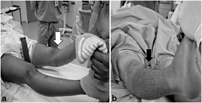

Fig. 16.4
Clinical exam findings of combined PCL and PLC injuries. a A markedly positive recurvatum-varus test (white arrow) indicates high-grade injury to the PLC, posterolateral ligaments, and posterolateral capsular supporting structures—an ideal indication for repair with a modified LaPrade reconstruction as described in the text. b Negative recurvatum-varus test in a patient whose MRI demonstrated injuries to the cruciates and lateral collateral ligament. The relative stability of the knee to rotation and varus makes this knee a potential candidate for a modified Larson sling procedure as described by Rios et al. [67]
Even in the absence of gross sagittal plane instability, it is the author’s preference to reconstruct/augment the PCL if clinical grade II (B) or worse instability is present (when the tibial plateau lies flush with the femoral condyles on draw testing). In cases where varus/valgus instability is appreciated, a careful comparison to the other extremity is useful. In trying to distinguish between acceptable (trace) instability versus physiologically relevant varus, it is often useful to arthroscopically measure the degree to which the lateral compartment opens to varus stress. Opening of greater than 8–10 mm is likely to create undue strain on the PCL reconstruction if the PLC is not addressed. Once the decision to proceed with reconstruction is reached, the lateral side is exposed prior to arthroscopic reconstruction of the central pivot. Dissection is easier prior to imbibition of the tissues with fluid, and the dissected lateral corner allows low-pressure fluid egress, thereby decreasing the risk of compartment syndrome.
Lateral Dissection and Lateral Reconstruction Preparation
The authors advocate augmentation of the PLC even when primary repair is possible, as outcome studies have shown repair with augmentation to be superior to repair alone [48]. In the literature, there are multiple methods of reconstructing the posterolateral corner. Scientific studies have yet to agree on a method of repair that most accurately reconstructs the native ligaments to a state that leads to an optimal clinical result. Good clinical results have been documented with multiple techniques including the Larson technique, anatomic reconstruction described by Arciero, and by anatomic reconstruction described by LaPrade and colleagues [52–54]. Although the merits of each technique can certainly be debated, significant importance should be directed at the effective implementation of a single technique rather than ineffective implementation of multiple techniques.
The severity of injury to the PLC may dictate the best technique for repair (Figs. 16.3 and 16.4). In cases where mild varus and external rotation instability is present in the absence of recurvatum, the authors utilize the Arciero modification of the Larson technique (Fig. 16.5). However, in cases of moderate-to-severe varus and/or external rotation instability, and any time recurvatum is increased, it is preferable to reconstruct the PLC using the technique described by LaPrade [53]. The senior author has modified LaPrade’s technique to employ suspensory fixation in the tibia, and base the FCL femoral tunnel on both isometric and anatomic landmarks (Fig. 16.6). This reconstruction technique theoretically reconstructs key determinants of lateral-sided stability by reconstructing/augmenting the lateral collateral ligament, creates a “static” popliteus limb that also buttresses the posterolateral capsule, and stabilizes the proximal tibiofibular articulation. The use of suspensory fixation allows for a reconstruction using a shorter graft length.
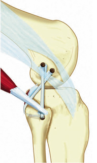
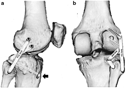

Fig. 16.5
Modified Larson sling PLC reconstruction technique as modified by Arciero (no tibial tunnel). (From [67]. Reprinted with permission from SAGE Publications)

Fig. 16.6
Lateral (a) and posterior (b) views of the modified LaPrade PLC reconstruction technique using suspensory fixation used by the author. A loop of the soft tissue reconstruction graft is pulled into a posterior tibial tunnel and fixed using suspensory fixation (black arrow). One graft limb (pop limb) follows the native popliteus tendon through the popliteal hiatus and is fixed using interference screw fixation at the anatomic insertion of the popliteus on the femur. The second limb (FCL limb) courses from the tibial tunnel into the posteromedial aperture of the fibular tunnel (stabilizing the tibiofibular articulation) and then courses along the path of the native FCL to the lateral epicondyle. Once the ideal (isometric) position of this tunnel is identified, it is tensioned and docked into the tunnel using interference screw fixation
Preferred Surgical Technique
Part 1: Incision, Identification of Anatomic Structures of the PLC, Review of Surgical Windows Incision and Peroneal Nerve
A “lazy-S” curved incision is made on the lateral side of the knee. The incision starts directly over the lateral epicondyle, and traverses distally toward the posterior aspect of the fibular head, curving gradually anteriorly along a 4.5- to 5-cm radius from Gerdy’s tubercle (Fig. 16.7). This incision will allow easy exposure of the peroneal nerve, posterior aspect of the fibula, and a limited exposure of the posteromedial tibiofibular joint.
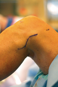
Fig. 16.7
Incision for PLC reconstruction (left knee). A “lazy-S” incision starts proximally over the lateral epicondyle and curves gently toward the posterior fibular head, curving along a radius approximately 4.5–5 cm from Gerdy’s tubercle
The peroneal nerve is typically found deep to a thin fascial layer at the posterior tendinous edge of the biceps femoris, approximately 4–6 cm proximal to the fibular head. The anatomy may be distorted by scarring or hematoma if injury to the biceps insertion, proximal fibula, or peroneal nerve has occurred.
The peroneal nerve is tagged with a short vessel loop and carefully dissected distally to the peroneal fascia (Fig. 16.8).
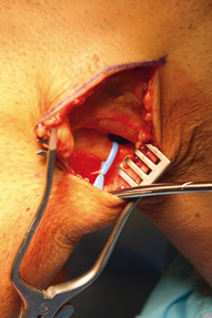
Fig. 16.8
The peroneal nerve is identified subfascially immediately posterior to the posterior border of the biceps femoris tendon. It is tagged with a vessel loop and followed distally toward the fibular neck. A peroneal nerve exploration and neurolysis can be performed if indicated
In cases of peroneal nerve neurapraxia, a peroneal nerve exploration and neurolysis is performed from proximal to the biceps distally around the fibular neck and into the anterior compartment of the leg.
Window 1: The Proximal Fibula and Posteromedial Tibiofibular Joint
The fibular collateral ligament normally inserts at the anterolateral aspect of the fibular head. A fibular reconstruction tunnel will be created just distal to this insertion at the widest point of the flare of fibular head. A minimal elevation of the periosteal insertion of the biceps femoris can be performed. Care should be taken not to stray distal to the widest portion of the fibular head, or injury to the peroneal nerve is possible where it courses around the fibular neck.
With the common peroneal nerve gently retracted posteriorly, the dissection is carried bluntly posterior to the peroneal muscle origins on the proximal fibula, leaving the soleus and gastrocnemius muscles posterior (window 1, Fig. 16.9). This plane is easily identified with blunt finger dissection across the posterior fibula to the posteromedial tibiofibular joint which is easily palpated. The tendon of the popliteus tendon can be palpated just medial to the posteromedial tibiofibular articulation as it enters the popliteus hiatus from outside the joint.
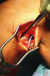
Fig. 16.9
Creation of window 1. A blunt dissection is carried out between the fibular head and proximal peroneal fascia (F) anteriorly and the lateral gastrocnemius tendon (GT) posteriorly. Care should be taken to free the peroneal nerve distally enough that with 90° knee flexion the posterior tibiofibular joint can be easily approached without undue tension on the nerve
Occasionally, the capsular insertion, biceps femoris, and FCL insertion will avulse en masse from the proximal fibula, with or without a bony avulsion or fracture of the fibula present.
Window 2: The Iliotibial Band and Lateral Epicondyle
A split of the iliotibial band is created directly over the lateral epicondyle and carried proximally 4 cm and distally in line with the ITB fibers to the insertion at Gerdy’s tubercle (Fig. 16.10). A Weitlaner retractor is placed to open the interval between the ITB and lateral capsule of the knee.
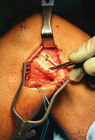
Fig. 16.10
Creation of window 2. The iliotibial band (ITB) is incised along its fibers at a point directly overlying the lateral epicondyle (asterisk). This fascial incision can be carried distally to the ITB insertion at Gerdy’s tubercle, and proximally as far as necessary to allow adequate retraction and visualization of the underlying lateral structures. The surgeon will work intermittently through window 2 and window 1, inferior to the biceps femoris tendon (BFT)
The origin of the FCL on the lateral epicondyle is located. In cases where the disruption of the FCL is proximal, there may be a bony avulsion off the epicondyle that can be tagged for repair.
The FCL can be palpated coursing from the lateral epicondyle toward the fibular head.
Window 3: The Lateral Capsule, Popliteus Insertion, and Hiatus
A limited arthrotomy is carried through the capsule just anterior to the fibular collateral ligament fibers (window 3, Fig. 16.11). Care must be taken to incise only the capsule, as the popliteus tendon insertion is present just anterior and distal to the lateral epicondyle and iatrogenic injury is possible. In addition, the incision can be carried distally to the superior margin of the lateral meniscus, but care should be taken not to cause iatrogenic laceration of the peripheral lateral meniscus.
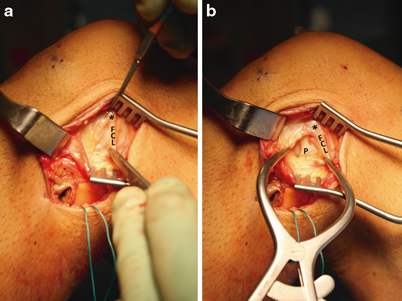
Fig. 16.11
Creation of window 3. a A Weitlaner retractor has been placed for retraction of the split iliotibial band. The fibular collateral ligament (FCL) can often be palpated if it has not been completely disrupted as it courses from the lateral epicondyle (asterisk) toward the proximal fibular head. The lateral capsule should be incised carefully beginning anterodistal to the lateral epicondyle and coursing longitudinally along the anterior border of the FCL. b Once the capsular incision has been started, a Gelpi retractor is placed. The capsular incision can be carried distally to the superior border of the meniscus. The popliteus tendon (P) insertion on the lateral fibula is identified, and the tendon can be visualized entering the popliteus hiatus of the lateral meniscus
If the popliteus insertion on the femur is disrupted, the popliteus tendon can usually be identified resting close to the hiatus and tagged for later repair.
The popliteus hiatus is easily visible just deep and slightly posterior to the FCL fibers. A passing suture can easily be placed from proximal to distal along the popliteus tendon through the hiatus using a curved clamp and retrieved through window 1 at the posterior tibiofibular articulation (Fig. 16.12).
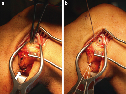
Fig. 16.12
Placing a passing suture for popliteus reconstruction limb. a A long Kelly clamp is placed through the popliteus hiatus visible through window 3, passing alongside the popliteus tendon (P) to window 1 (white arrow). b A #2 braided suture is retrieved using the clamp. This suture will be used to shuttle the popliteus reconstruction limb for either the Arciero or modified LaPrade reconstructions
Once all anatomic structures have been identified and tagged for repair, the iliotibial band is closed temporarily to abate excessive arthroscopy fluid outflow while reconstruction of the central pivot (ACL and PCL ) is completed. For pearls related to reconstruction of the PCL, please refer to Part 4.
Part 2: Repair and Reconstruction of the Posterolateral Corner (Modified LaPrade Technique)
Repairs with augmentation or reconstruction of the PLC should proceed after all central pivot structures have been stabilized (ACL and/or PCL reconstruction ). This is because the author’s modification of the LaPrade technique relies on the isometry of the fibular collateral insertion near or at the lateral epicondyle which may be highly abnormal when ACL and/or PCL laxity is present. Anatomic repairs of all injured structures are performed. Avulsions from bone are repaired using suture anchors. It is common with chronic FCL ruptures or midsubstance ruptures that the ligament is too short to be repaired anatomically. In such cases, the torn native remnants can be sewn to the reconstruction grafts using absorbable braided #0 or #1 suture. Also, chronic ruptures of the biceps femoris not infrequently shorten to the extent that they cannot be repaired primarily without undue tension in extension. It is the author’s preference to repair the attenuated biceps femoris to a length of allograft tendon (placed through the fibular reconstruction tunnel) alongside the FCL reconstruction limb.
Fibular Tunnel
A slotted Beath pin will be used to create a tunnel through the fibula with a diameter that matches the single-diameter of the graft (unless a second graft is required to augment an attenuated biceps femoris avulsion). In most cases when using a semitendinosus autograft or tibialis anterior allograft, a 5- to 6-mm tunnel will be sufficient.
A starting point for a reamer guide pin through a minimal subperiosteal window is created just posterior and inferior to the native FCL insertion at the anterolateral fibula (at the widest point of the flare of the fibular head) (Fig. 16.13a). The pin is directed slightly medially and slightly inferiorly to exit the fibular head at its posteromedial edge, just lateral to the posterior tibiofibular joint. The pin exit can be carefully palpated at the posteromedial fibula prior to over-reaming (Fig. 16.13b). Care must be taken to make the tunnel along the widest diameter of the fibular head to create an adequate tunnel and avoid iatrogenic fracture of the proximal fibula.
The pin is over-reamed to the diameter of the reconstruction graft (Fig. 16.13c).
A passing suture can be passed using a HEWSON™ suture passer (Smith & Nephew, Andover, MA) or by passing suture via the slotted end of the Beath pin through the tunnel and retrieving it through window 1 (Fig. 16.13d).
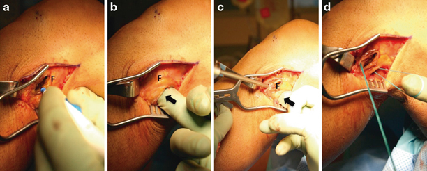
Fig. 16.13


Creation of the FCL reconstruction tunnel. a A small subperiosteal approach is made at the widest point of the anterolateral fibula (F), just distal to the native FCL insertion. A bovie cautery device is utilized and care is taken not to continue the elevation distally onto the fibular neck to avoid injury to the common peroneal nerve. b A finger is placed through window 1 (black arrow, interval between the fibula and anterior gastrocnemius/soleus fascia) and the posteromedial tibiofibular joint is palpated. A guide pin is placed along a trajectory from the anterolateral to the posteromedial fibular head, at the widest point of the metaphyseal flare. c A reamer is used to create a tunnel with a diameter that matches the reconstruction graft. A finger or retractor should be utilized (black arrow) to avoid injury to underlying neurovascular structures. d A loop of braided suture is placed to aid in graft passage
Stay updated, free articles. Join our Telegram channel

Full access? Get Clinical Tree


