Surface Coil Imaging
Tom Schubert

Certain nuclei in the human body have a property called magnetic “spin.” This magnetic spin occurs at a specific radiofrequency called the Larmor frequency. Several of these nuclei are found in the body in enough abundance to generate an image.1 The element of interest in most MR applications is hydrogen. Hydrogen is bound in water and in fat (in hydrocarbon chains), and there is an abundance of fat and water, and therefore hydrogen, in the human body. In fact, the human body is made up of 63% hydrogen, making hydrogen an ideal element for imaging. The biological abundance of hydrogen is 0.63.1 Other elements with the magnetic spin property are much less abundant in the body and are thus much more difficult to detect and image. The biological abundance of sodium, for example, is 0.00041.1
The Larmor frequency of hydrogen is about 42.58 MHz per Tesla. Therefore, when hydrogen is immersed in a magnetic field of 1 Tesla (1T), it resonates and precesses at a frequency of about 42.58 MHz. At 1.5 Tesla (1.5T), the precession frequency is approximately 64 MHz; naturally, at 3.0 Tesla (3T), the precession frequency is approximately 128 MHz.
Design and Definition of Radiofrequency Coils
MR systems work by depositing radiofrequency (RF) en ergy into the patient, usually using the MR system body coil. When a tiny portion of that RF energy is released from magnetic spins of nuclei, it can be detected by special radiofrequency antennas called coils. Coils are often referred to as RF coils, surface coils, RF antennas, receiver coils, or array coils. The term “RF coils” is used in this chapter.
An RF coil is an electrical circuit. To make the coil very sensitive, it is designed to resonate at the frequency of in terest, much like a tuning fork is very sensitive to sounds or vibrations at a certain frequency. In electrical terms, a resonant circuit is an RLC circuit —that is, the resonant frequency of the coil is determined primarily by the resistance (R), the inductance (L), and the capacitance (C) of the circuit elements. By adjusting these three variables, RF coils can be “tuned” and “matched” to 64 MHz. The tune and match are electrical measures of how well an RF coil is
designed to pick up signals at the frequency of interest and deliver them to a receiver.
designed to pick up signals at the frequency of interest and deliver them to a receiver.
When an RF antenna is brought near a patient, the antenna becomes “loaded” by the patient. Larger patients load the antenna more heavily and smaller patients load the antenna less heavily. For optimal signal-to-noise (SNR) performance, the RF antenna must be impedance-matched to the patient load. In addition, the patient load slightly affects the resonant frequency of the antenna. A coil must be properly tuned and impedance-matched to a specific patient load to achieve the best possible performance. Although early MR systems called for tuning and impedance-matching the coil on a per-patient basis, this resulted in a great deal of complexity in both the RF coil and the MR system, with a loss of reliability. Today, therefore, most coils are “fixed tuned”—in other words, the resonant frequency of each antenna and the impedance-matching to the patient load is set by the electronic circuit elements and does not change. The result is a slight loss in performance when imaging a patient whose body habitus differs from the patient load for which the coil was optimized.
MR system manufacturers are seeking solutions to the complexities of coil array design outlined in the following discussion. Advances in the next few years are likely to include conversion of RF signals at the coil antennas to light signals transmitted to the MR system via optical fibers. It is also possible that the RF signals will be digitized prior to transmission. This will obviate many of the cable issues and decrease the importance of many of the coupling issues. Another alternative under investigation is wireless transmission of the RF signals.
Design of RF Coils
To better understand the technical challenges of coil design, a brief review of the components of RF coils is presented. The basic components for an RF coil are:
Resistance
Inductance
Capacitance
Therefore, a simple RF coil could conceivably consist of a coat hanger with a single capacitor between the ends. The wire in the coat hanger has resistance, the loop of the coat hanger has inductance, and by adding a capacitor an MR image could be made with it. However, RF coils today are much more sophisticated.
Decoupling
The MR system body coil deposits a large amount of RF energy into the patient. Since the coil receiving the signal from tissues must be a resonant circuit, it also detects the RF energy from the MR system body coil. This energy is many thousands of times stronger than the RF energy emitted by the tissue. If the RF coil is not “turned off” during the body coil transmit cycle, it will absorb a large amount of energy from the MR system body coil, which can destroy the electrical components of the RF coil; generate tremendous heat, leading to smoke or fire; or generate high electric fields, which can cause an electric field burn in the patient.
Turning the RF coil off is referred to as decoupling.2 The coil is, in effect, decoupled from the transmit field generated by the MR system body coil. This is done using active electronic components known as diodes. The MR system provides a control signal (a voltage or a current) to each RF coil through the coil cable. This control signal is used to drive the diodes into a conducting or nonconducting state. This engages, or disengages, small circuits on the RF coil, which shift the resonant frequency of the RF coil away from the operating frequency of the MR system. This has the effect of minimizing the RF currents on the coil, thereby effectively turning the RF coil off. This is known as active decoupling.3
It is so important to turn the RF coil off during the transmit cycle of the MR body coil that at least two, sometimes three, redundant methods are employed. Of course, if the MR system operator fails to plug the RF coil cable in, or the coil plug becomes loose, the electrical signals provided by the MR system will not reach the RF coil. In that case the coil will not be actively decoupled. There are often diode networks in the RF coil that turn on passively, without the need for voltage supplied by the MR system. These networks extract a small amount of energy from the transmit field generated by the MR system body coil to engage the diodes to turn the coil off. This is known as passive decoupling.
Diode Technology
Diode technology is a somewhat proprietary art in the RF coil industry. Most diodes used in RF coils today were developed for other electronic applications, although some RF coils have diodes customized for RF coil applications. In the future, diodes or other electronic switches may become available that are more suitable and robust for RF coil applications.
One of the major weaknesses of diodes is that they can fail. If a diode fails in the shorted condition, the RF coil is permanently decoupled. The RF coil will not “see” the MR system body coil, nor will it see the RF signals emitted from the patient. However, if the MR system body coil continues to operate, enough energy may continue to go into the RF coil to melt the diode. In that case, the diode becomes open, and the RF coil becomes resonant again. For this reason, at least one MR manufacturer requires each antenna element in an RF coil to have a fuse. If the diodes fail, the fuse melts, permanently turning the RF coil off. This is the ultimate fail-safe feature to prevent patient burns. However, fuses by definition tend to have a measurable electrical resistance, and this resistance results in a slight reduction of the performance of the RF coil.
Some MR systems periodically test to see if there is a voltage drop across the diodes, thus checking to see if the diodes are intact. This diode check may occur before a scan starts, or even during a scan. This check also serves to determine whether an RF coil is plugged in to the MR system.
It is important to understand that coils cannot be turned off completely. The degree of “offness” is usually measured in dB. If an RF coil is not turned off very well, certain image artifacts can result. In particular, not decoupling a coil well can lead to a distortion in the B1 transmit field of the body coil. This can result in a failure of “Fat Sat,” the chemical saturation technique inherent in certain pulse sequences.
Coil Cables
A cable connects the RF coil to the MR system. Part of this cable also lies within the MR system body coil and is subject to absorption of RF energy from the MR system body coil. This can lead to high RF currents or standing waves occurring along the coil cable, potentially resulting in fire or patient burns. Various techniques are used to suppress standing waves on the coil cable; these are referred to in the coil industry as cable traps or baluns.4 These devices are most prevalent on 3T RF coils. They usually can be seen as plastic barrels in the RF coil cable.
Other Aspects of RF Coil Design
Ferrous Metals
RF coils cannot contain ferrous materials (such as iron, nickel, and cobalt) since these materials will distort the B0 magnetic field of the MR magnet and result in a hole in the MR image near the coil, commonly known as a metal artifact. Occasionally, however, electronic components containing ferrous materials have been unintentionally used in the manufacture of RF coils. Nickel, for example, is a common plating used for electronic components, and nickel plating has sometimes been found to have been applied as a diffusion barrier under the gold or silver plating specified. This ferrous content can be very difficult to detect, except of course in an MR system.
Antennas and Coil Housing
The RF antennas in a coil are generally encased in a coil housing made of plastic. Since plastic is made of hydrocarbons and contains hydrogen, the plastic chosen for the coil housing must have very little “proton signal”—that is, the number of free hydrogen molecules in the plastic must be so small that the coil housing is not visible in the MR image. Each MR system manufacturer has its own test for proton signal in coil housings. As pulse sequences with short TEs, which can make the proton signal coming from plastic more apparent, become more popular, this issue is becoming increasingly important.
In addition to having as little proton signal as possible, the plastic coil housing must be very robust so it does not crack during use or even if dropped on the floor. In addition, the plastic must be highly flame-retardant and must be rated by one of the materials rating laboratories. To achieve the desired flammability rating, the plastic must be of a certain minimum thickness when molded into a complex shape.
The plastic material must also be an excellent insulator. A high electrical potential test must be passed, and the coil housing must hold off 5,000 volts DC. The seams in the coil housing must also be designed to achieve a minimum “creepage distance.” This distance must be long enough so that the air path through the seam from the patient to the electronics in the coil provides a minimum amount of dielectric insulation.
The seams in the coil housing must also be designed so that the coil will pass a fluid ingress test. During this test, the housing is sprinkled with water while several thousand volts are applied to the circuitry inside the coil housing. If water leaks into the RF coil housing, there will be a discharge of electricity from inside the coil to the outside. The purpose of this test is to ensure that the coil housing design prevents electric shock to the patient in the event the patient bleeds, urinates, or regurgitates during the scan.
It is important that no part of the coil that comes in contact with the patient rises by more than a few degrees in temperature during extended use. This means that components that dissipate significant energy, especially decoupling circuits, must be carefully designed and placed in locations that will not significantly raise the temperature of the coil housing in patient contact areas.
Image artifacts may arise from rapid switching of MR system gradient coils. This typically happens during sequences known as echo planar imaging (EPI). The rapid switching induces current flow in the copper of the antenna circuit in the RF coil. Any conductor in which a current is flowing has its own magnetic field. This magnetic field distorts the B0 magnetic field of the MR system magnet, resulting in what is known as an eddy current artifact. To reduce or eliminate eddy current artifacts, the RF antenna loop has frequent electrical breaks bridged by capacitors, and the number of copper conductors used to shield components such as preamplifiers is minimized to the extent practical.
Patient Safety
As mentioned above, decoupling is essential for patient safety. In addition, it is very important that the RF coil cable is not coiled into a loop. Since a loop of wire has inductance, a loop in the coil cable can easily cause the cable to become a resonant circuit at or near the system operating frequency (see RLC circuits discussed earlier). Again, this could result in the loop absorbing a great deal of RF energy from the MR system body coil, and a fire or electric field burns to the patient could easily result. This phenomenon may occur whether the coil cable is attached to the MR system or not. It may also occur with other electrically conductive cables, such as ECG leads, or even a bracelet or necklace or underwire brassiere the patient is wearing.
RF coil cables often have a thick layer of insulation to help prevent an inductive loop from forming and to ensure a minimum distance from the patient to the cable. In addition, baluns or cable traps may be built into the RF coil cable at certain locations to suppress surface waves on the cable. Finally, RF coil cables are kept as short as possible, thus making it difficult for the MR system operator to inadvertently loop the cable.
Coil Designs for 3T MR Systems
Converting a successful RF array coil design from 1.5T to 3T is not simply a matter of retuning the antennas and preamplifiers from 64 MHz to the 128-MHz operating frequency of a 3T MR system (although the opposite may be true). In general, overlapping of adjacent antennas can create significant capacitance, causing coupling between the antennas. This effect is much more problematic at 128 MHz, and the higher operating frequency gives rise to greater coupling between antennas in the coil array. Since preamplifier decoupling methods limit only inductive coupling of antennas, great care must be exercised in reducing stray capacitance in antenna arrays operating at 128 MHz.
Cabling for 3T array coils is another important aspect of design, and cables create a serious technical hurdle at 3T. Each antenna loop must be connected to a receiver in the MR system in some way. This is usually accomplished using a coaxial cable. There are often interactions among the coaxial cables connecting the many antenna elements to the MR system, and random coupling between coils and cables invariably degrades SNR. Normally, MR systems with many channels require that all coaxial cable shields be connected to a common RF ground point. However, as illustrated in Figure 2.1, connecting all of the antennas to a common ground point can create many more “loops” of wire. These loops can potentially become antennas resonating near 128 MHz, which might then pick up energy from the MR system body coil. When these current loops interact with the antenna loops in the receive state, they may cause unwanted coupling, resulting in losses of SNR and uniform reception. In addition, the currents induced on coaxial cable shields can become very high during the transmit cycle of the MR system body coil, creating the potential for patient burns and arcing.
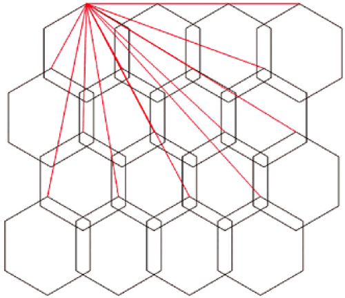 FIGURE 2.1 ● A 2D coil array, four antennas wide by four antennas long. The red lines represent the shields of the coaxial cables that must be attached to a common ground point. |
Related posts:


Stay updated, free articles. Join our Telegram channel

Full access? Get Clinical Tree


