CHAPTER 21 Radiation Safety – Theory and Practical Concerns
BASIC TERMINOLOGY
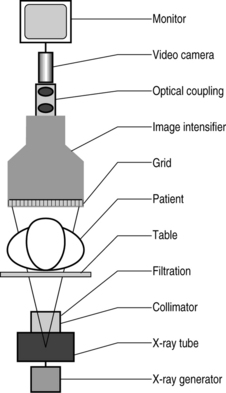
The X-ray generator produces X-rays when an electrical current is applied to it. The X-ray generator is a device that acts as the primary control mechanism for the entire fluoroscope. It is through the X-ray generator that current is allowed to flow into the X-ray tube. The basic function of adjusting the voltage differential and current of the X-ray tube are controlled automatically to maintain optimal contrast and brightness. Generator types used in fluoroscopy include single phase, three phase, constant potential, and high frequency. High-frequency generators provide superior exposure reproducibility along with the most compact size, lowest purchase price, and lowest repair costs. As a result, high-frequency generators are commonly used in new radiographic equipment.1 X-rays may be generated in either a continuous or a pulsed mode. Automatic brightness control is a standard feature of the majority of modern fluoroscopes. Through this system mA and kVp are constantly monitored and adjusted to optimize the image.2
The X-ray source is generally referred to as either the ‘anode’ or the ‘cathode.’ Both of these terms are in fact inaccurate. The source of X-rays is the cathode ray tube. As ‘cathode ray’ is an outdated term and the tube contains both a cathode and an anode the correct term would appear to be simply X-ray tube, or X-ray source.1
The cathode (negatively charged electrode) is a cup-shaped holder with a coiled wire filament. The wire is made of tungsten. When the wire is heated, it emits electrons. The cup shape of the cathode serves to focus the electrons so they will strike a specific point on the anode target.2
The anode (positively charged electrode) attracts the electrons emitted by the cathode. The anode is usually made of copper. The target is an area of tungsten on the face of the anode. The specific point at which the electrons are focused is called the focal spot. The focal spot is where X-rays are generated. Due to the amount of heat generated by this reaction many X-ray tubes use a ‘rotating anode.’ The rotating anode dissipates heat more effectively, thereby prolonging the life of the X-ray tube.1
The collimator is an iris and/or set of sliding plates of radiopaque material that defines the shape of and limits the size of the X-ray beam. Use of collimation has another important effect. By reducing the area of the X-ray beam, the amount of scattered radiation that reaches the image receptor is also decreased. The resulting images have better contrast. It sits in line immediately after the X-ray tube but before the filtration.1
Filtration X-rays of differing energy levels are generated by the X-ray tube. Only the high-energy beams are useful for producing an image of the patient, yet the low-energy beams will contribute to dose. Therefore, it is essential in overall dose management and image refinement to filter out all nonessential beams. This is done with either copper or aluminum filters. It is important to note the presence of ‘inherent filtration’ in all X-ray systems. Inherent filtration consists of the glass casing of the X-ray tube and the surrounding coolant oil. Inherent filtration is usually expressed in millimeters of aluminum equivalent (typically 0.5–1.0 mm).1
Beam equalization filters are partially radiolucent wedge-shaped (tapered) blades and are constructed of lead-rubber or lead-acrylic sheets. They sit at the margins of field and are used to compensate for variations in the radiodensity at the edge of the patient, particularly when moving from a larger to a smaller section of the body. They provide for an image of relatively even consistency. They improve operation of the automatic brightness control system.1
The grid is a radiotransparent plate composed of a radiopaque material aligned perpendicular to the beam such that only those X-rays traveling in the intended direction can reach the image intensifier, thus minimizing ‘Compton-scatter fog’ by only allowing those X-rays with the intended angle of incidence or very close to the intended beam angle of incidence to strike the image intensifier. However, it also prevents some useful photons from contributing to the image. For this reason, while a grid reduces Compton scatter it also necessitates a higher mA setting, thereby increasing the exposure to the subject.1
The image intensifier is designed to convert the X-ray image into a visible real-time image. Rather than use the focused beam of X-ray energy to produce an image on film, the fluoroscope converts this energy into light photons by accelerating and focusing them, through a series of electrodes, onto an ‘output phosphor.’ The characteristics of this output phosphor impregnated upon the viewing screen of the image intensifier play a role in determining the amount of energy required to produce an image. Most modern image intensifiers use cesium iodide for the input phosphor due to its high absorption efficiency. This decreases patient dose.3
Optical coupling, video camera and monitor: When one looks at the screen of a modern fluoroscope, the image directly viewed is not produced by the image intensifier. Modern imaging technology has allowed for a series of refinements in imaging. An optical coupling device interfaces with the image intensifier, assuring proper transference of the image to a video camera. Most modern fluoroscopes use digital imaging technology in order to produce images that are more easily manipulated in cyberspace. This is where technology is introduced into the fluoroscope. Additionally, the video monitor provides a superior image to the image intensifier (Fig. 21.1).4
RADIATION SAFETY TERMINOLOGY
X-rays are any of the rays produced when cathode rays strike upon the surface of a solid (such as the wall of the vacuum tube). An X-ray is a form of electromagnetic energy of very short wavelength (0.05–0.06 angstrom), which allows it to readily penetrate matter.5 X-rays are also noted for their action on photographic plates, their ability to ionize gases, and their fluorescent effects, as well as the fact that they cannot be reflected, polarized, or deflected by a magnetic field.2 They were called X-rays by their discoverer, W. K. Roentgen. X-rays and gamma rays are identical in their physical properties and biologic effects except that gamma rays are natural products of radioactive atoms and X-rays are produced in man-made machines.3 X-rays are produced by the acceleration of electrons (negatively charged particles) via the heating of a cathode. These electrons are then accelerated towards a positively charged anode based on the kilovolt potential across the terminals. Two separate processes produce radiation at the anode. First, as the electrons approach the anode, they produce radiation via a process referred to as bremsstrahlung, a German word for ‘brake radiation.’ In this process the high-speed electrons themselves give off radiation as they decelerate or come to a complete stop in passing near the positively charged nuclei of the anode material. In a second process, the electrons of the anode atoms emit radiation when incoming electrons from the cathode knock electrons near the nuclei out of orbit. These electrons must be replaced. The replacement electrons come from higher-energy outer orbits. As these outer orbit electrons drop down to a lower energy state, they lose energy. This energy is given off in the form of X-ray radiation. This process is referred to the K-shell process. The anode material used in a given X-ray tube determines the spectrum of frequencies given off by that X-ray tube.6
kVp (kilovoltage peak) is the voltage differential between the cathode and anode in the X-ray tube. kVp is generally set at 50–120 kV. kVp influences the force of attraction experienced by an electron drawn from the cathode to the anode. This is an accelerating force. If kVp is increased, the kinetic energy of the electron will be increased. An increase of the maximum energy photons in the beam will occur. This acceleration controls the quality of the X-ray beam. The higher the voltage, the greater the speed of the electrons and therefore the penetrating power of the X-ray beam.1
mA (milliamperage) is the current setting for fluoroscopy, and typically ranges 0.5–5 mA. Increasing the current in the radiograph tube increases the number of X-ray photons emitted per second. If the current (mA) through the X-ray tube is doubled, the number of electrons flowing across the tube is doubled.1
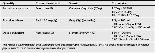
The rad is the Conventional unit used to measure the quantity of radiation and is equal to 0.01 Gy.
The sievert (Sv): Particles of ionizing radiations other than X- and gamma rays, such as particles or neutrons, may induce a greater biologic effect per gray. The Sv is an International unit used to measure the dose equivalent and is equal to the number of grays multiplied by a quality factor ranging from 1 to 20 that expresses the degree of biologic insult for equal doses of different types of ionizing radiation. The quality factor for X- and gamma radiation is equal to 1. The quality factor of 1 is simply a number assigned to the most commonly used and manipulated form of ionizing radiation in order to allow all forms of ionizing radiation to be ordered according to their potential to produce biological insult (Table 21.1).
Kerma: To characterize an X-ray field, the quantity of exposure is being replaced by the quantity of air or kerma. Kerma (an acronym for kinetic energy released per unit mass) is defined for air as well as for other interacting media such as tissue. Kerma takes into account the bremsstrahlung interactions in air and tissue. The unit of kerma is the gray (formerly, rad; 1 Gy = 100 rad). Exposure excludes any further energy loss by the charged particles that are subsequently given up as photons or to other charged particles (i.e. exposure discounts the bremsstrahlung interactions).10
Scatter radiation is the primary source of radiation exposure to radiology personnel, particularly the interventionist. Scatter is the result of X-ray beams failing to penetrate the patient or any surface they are aimed at and therefore being ‘reflected’ away in another direction. Scatter radiation comes in two forms: primary and secondary. Primary scatter is the radiation scatter coming directly off of the patient’s skin surface. Secondary scatter results from the X-rays that fully penetrated the patient and had incidence upon the grid. Some of these will be scattered as well.10
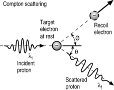
Compton scattering is the scattering of photons from charged particles. It was named after Arthur Compton who was the first to measure photon-electron scattering in 1922. This is the process by which X-rays are generated (Fig. 21.2).
‘Half-value layer’ (HVL) quantifies the beam quality, representing the penetrability (or energy) of the X-ray beam. As a characteristic of individual beams, and therefore individual X-ray machines, the HVL is a means of describing the quality of the beam produced by a given X-ray machine. An important factor to note is that as the beam of an X-ray passes through X-ray filters, its HVL increases. This is a function of the lower energy portion of the beam being removed. The remaining beam is proportionally more penetrative. This is normally expressed in aluminum or copper thickness and is measured at specific kVps. A beam is more penetrative/of higher quality if it has a higher half-value layer. The more penetrating the beam the harder the radiation.5
FUNDAMENTALS OF X-RAY GENERATION
Electrical current that is open and flowing is always surrounded by a magnetic field.8 The process of electromagnetic induction can produce current from a second wire. Since both coils are not electrically connected, placing a second coil of wire adjacent to the first coil induces an electrical current in the second coil by mutual induction. The force in the second wire loop is directly proportional to the number of turns in the first wire loop.
The X-ray circuit is divided into a low voltage or primary subsection and a high voltage or secondary circuit.10 The primary circuit consists of the following:
The secondary or high-voltage circuit consists of:
Voltage (kVp) is adjustable over a range of approximately 50–120 kV; the current (mA) setting for fluoroscopy typically ranges 0.5–5 mA. Increasing the current in the radiographic tube increases the number of X-ray photons emitted per second and increases the image contrast; increasing the voltage of the tube increases the energy of each individual photon and primarily effects brightness. Decreasing the voltage (kVp) and thus the energy of the particles by too large of an amount allows fewer particles to pass through the patient’s tissue and strike the image intensifier. Contrast and brightness are controlled by the automatic brightness control.1 It is generally considered good technique to use a high voltage (kVp) to attain a useful contrast and a low current (mA) to achieve the desired brightness. If the quality of the picture were improved by increasing the kVp by 15%, the mA would need to be doubled to obtain a similar level of improvement with only a current increase.
The most effective guidelines for the optimal initial tube settings on a fluoroscopy machine call for the current (mA) to be set at the lowest possible level and the energy (kVp) at the highest possible setting that will produce a useful image; nominal initial values may be 1 mA at 75 kVp.11 The current starts at 1 mA and is ramped up from there to minimize the amperage used to achieve optimal brightness. If one examines the logic of this carefully, it is perfectly reasonable. Adding current to the system simply uses more electrons to provide more radiation. Increasing the kVp derives more radiation from the same number of electrons by accelerating those electrons. The software in digital fluoroscopy essentially monitors the intensity of the radiation striking the image intensifier surface and within milliseconds adjusts the X-ray tube output and exposure time to optimize the image quality and minimize the radiation dose. Frame grabbing (storing images to disc) avoids the need for many spot films. This makes it essential that the fluoro device have two monitors: one for maintaining stored images for reference and one for viewing in real time. The most important dose-reduction feature available with digital equipment is variable pulsed fluoroscopy.12 Rather than delivering a constant X-ray beam to maintain the image on the screen, the pulsed mode delivers X-rays intermittently, with the most recent image being displayed until the next one becomes available (last image hold).
Absorbed dose quantities and units for quantifying biologic risks
Absorbed dose refers to the energy that is deposited locally in an absorbing medium from ionizing radiation. For the energies typically used in diagnostic X-ray procedures, absorbed dose and kerma are equivalent. By contrast, for high-energy photon interactions, the more highly charged particles may deposit energy at sites distant from the initial interaction site, with a corresponding loss of electronic equilibrium. In this case, absorbed dose and kerma are not equivalent. The unit of absorbed dose is the gray, which is the same unit as for kerma, and 1 Gy of absorbed dose is equivalent to 1 J of energy absorbed by the medium per kilogram of absorbing medium. One gray of absorbed dose is equivalent to 100 rad, the traditional unit of absorbed dose. Doses, including skin dose, include the contributions from scattered radiation in addition to the primary radiation. Organ doses consist of the total energy absorbed by an organ per unit mass of the organ.1
Practitioners are often concerned about the absorbed dose to the eye, inducing cataracts.13,17,18 This biologic effect appears to have a threshold in that about 6 Gy of diagnostic X-irradiation over several weeks is necessary to produce cataracts in humans. It may be that absorbed doses of about 15 Gy are necessary to induce cataracts in the diagnostic fluoroscopy setting (Tables 21.2–21.4; Fig. 21.3)
Stay updated, free articles. Join our Telegram channel

Full access? Get Clinical Tree


