Periacetabular Osteotomy
Rachel Yvonne Goldstein
Michael B. Millis
INDICATIONS/CONTRAINDICATIONS
Age: There is not a set age range for this procedure; instead, upper and lower limits for a periacetabular osteotomy are dependent on hip maturity and viability.
Lower limit: open triradiate cartilage
Upper limit: none specific to age
Indications
Symptomatic, congruous acetabular dysplasia
Mechanical instability correctable by acetabular redirection
Lateral and anterior center edge angles less than 20
Contraindications
Absolute
Hinged abduction
Tonnis grade 2, or worse, osteoarthrosis
Severe limitation of motion
Uncontrolled inflammatory joint disease
Active joint infection
Joint incongruity
Relative
Correctable muscular weakness
Negative patient-related factors
GOALS
Normalize Tonnis acetabular roof angle (0 to 10 degrees)
Correct subluxation
Normalize mechanical stability
ANATOMIC CONSIDERATIONS
Important landmarks
Iliopectineal eminence: marks the medial-most extent of the acetabulum
Infracotyloid groove: just distal to the acetabulum where the obturator externus tendon lies; this is the site of the anterior ischial osteotomy
Anterior superior iliac spine (ASIS)
Anterior inferior iliac spine (AIIS)
Apex of the greater sciatic notch
Ischial spine
Posterior column
Triangular and thickest just posterior to the acetabulum
Becomes thinner closer to sciatic notch
Optimal plane for the posterior column is angled obliquely to the medial cortex and perpendicular to the lateral cortex of the ischium posterior column.
PREOPERATIVE PLANNING
Clinical
History
Pain: May be insidious onset
Localized to the following:
Groin
Lateral aspect of hip
Anterolateral thigh
Buttock
Activity-related pain
Walking
Running
Standing
Impact activities
Pivoting on affected side
Prolonged sitting
Night pain
Mechanical symptoms
Locking
Catching
Instability
Gait disturbance
Limping
Antalgic gait: shortened stance phase
Abductor lurch/Trendelenburg gait
Limited walking distance
Physical examination
Limp
Antalgic gait
Abductor lurch/Trendelenburg gait
Standing Trendelenburg sign
Hypermobility
Range of motion
Steady the pelvis with one hand
Feel for “soft” endpoints
Specific testing
Anterior-posterior impingement tests
Apprehension test
Abductor strength testing
Imaging
Radiographs
Anterior-posterior (AP) view of the pelvis with patient standing the beam centered on the femoral heads (Fig. 21-1A)
Allows for assessment of lateral coverage using the lateral center edge angle (Fig. 21-1B)
Demonstrates inclination of the weight-bearing zone of the acetabulum (Fig. 21-1C)
False-profile view of both hips (Fig. 21-2A)
Assesses the anterior coverage of the femoral head (Fig. 21-2B)
Look for anterior joint space narrowing
Maximum abduction with internal rotation AP view of both hips (Fig. 21-3)
Mimics the correction that can obtained with the PAO
Demonstrates the congruence of the articulation
CT scan
Generally only required for complex deformities
MRI (Fig. 21-4)
Evaluate intra-articular structures for labral tears and articular cartilage damage
“Biologic” techniques, such as delayed gadolinium-enhanced magnetic resonance imaging of cartilage (dGEMRIC), can be used to assess cartilage health.
With associated cuts through the femoral condyles, can be used to assess version
Arthroscopy (Fig. 21-5)
If intra-articular pathologies, such as labral tears, Cam lesions, or loose bodies, are present, consideration should be given to concomitant treatment with arthroscopy.
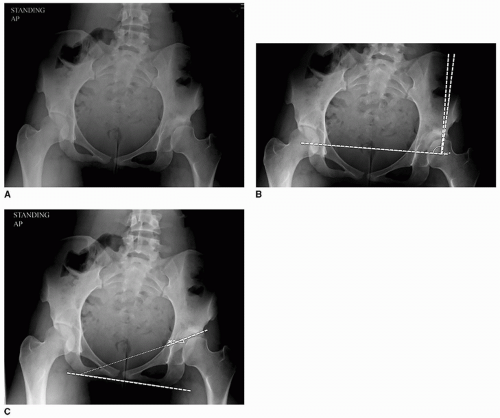
FIGURE 21-1 A. Standing anterior-posterior radiograph of the pelvis with the beam centered on the femoral head. B. Lateral center edge angle. The center edge angle is obtained by drawing a vertical line through the center of the femoral head perpendicular to the horizontal line extending through the center of both femoral heads. A line is then drawn from the center of the femoral head to the most superolateral point of the acetabulum. Normal values are greater than 25. Twenty to 25 degrees are considered borderline, and a lateral center edge angle of less than 20 degrees is considered diagnostic of acetabular dysplasia. C. Tonnis (acetabular roof) angle. Measured between the horizontal and an oblique line from the most medial point of the weight-bearing acetabulum to the most lateral point of the acetabulum. Normal values are less than 10 degrees. Used to evaluate the orientation of the acetabular roof in a coronal plane.
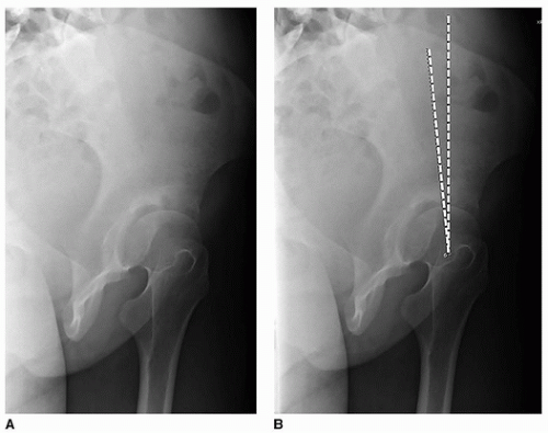
FIGURE 21-2 A. False-profile view. The view is obtained with the patient standing and the pelvis rotated 65 degrees relative to the film. B. Anterior center edge angle. It is measured by drawing a vertical line through the center of the femoral head and an oblique line running from the center of the head to the most anterior point of the acetabulum. Used to determine the anterior and superior coverage of the femoral head on the false-profile view. Normal values are greater than 25 degrees.
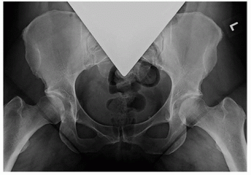
FIGURE 21-3 Von Rosen view. Maximum abduction with internal rotation AP view of both hips.
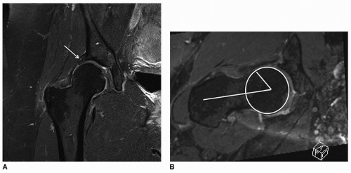
FIGURE 21-4 A. dGEMRIC MRI coronal view showing hypertrophied labrum (white arrow) consistent with acetabular dysplasia. B. dGEMRIC MRI radial view showing calculation of the alpha angle, an indicator of asphericity of the femoral head.
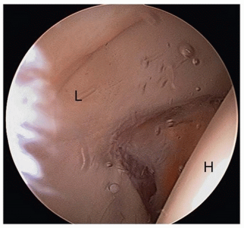
FIGURE 21-5 Arthroscopic view of a patient with acetabular dysplasia. Note the large, hypertrophied labrum (L). The femoral head (H) appears to the right.
Can be performed in the same surgical setting as the PAO
Allows visualization of the joint and treatment of intra-articular pathology
Never indicated in isolation in the treatment of symptomatic acetabular dysplasia
SURGICAL TECHNIQUE
Anesthesia
A multimodal preoperative combination of Tylenol, gabapentin, and oxycodone is useful.
Consider regional adjuvant such as an epidural or lumbar plexus block that can be maintained until postoperative day 2.
Positioning (Fig. 21-6)
Supine on radiolucent table
Operative extremity prepped and draped free:
Proximally to costal margin
Posteriorly to at least the posterior third of the ilium
Medially to the umbilicus
Approach (Fig. 21-7)
Historically, standard incision has been a Smith-Petersen longitudinal incision.
More user-friendly for the relatively inexperienced surgeon and anatomically complex hips
Alternatively, an ilioinguinal (bikini) incision may be used.
Provides better cosmesis
Can limit access for anterior ischial osteotomy
Easier to perform in smaller or less muscular patients
Superficial dissection
Incise skin and subcutaneous tissue.
Fascia over the external oblique and gluteus medius is identified and incised posterior to the ASIS.
Identify the plane between the external oblique and the gluteus medius and develop it to expose the periosteum over the iliac crest.
Periosteum is sharply divided over the iliac crest and subperiosteal dissection carried out over the inner table of the ilium. This space should then be packed with sponges for hemostasis and to aid in retraction.
Enter into the tensor fascia lata (TFL)-sartorius interval (Fig. 21-8)
Accomplished via the compartment of the proximal TFL to avoid injury to the lateral femoral cutaneous nerve
Fascia directly over the TFL is incised.
TFL is bluntly elevated off the intermuscular septum.
Compartment floor is identified proximally until the anterior ilium is palpated.
Predrill the ASIS using a 2.5-mm drill to aid in later reduction of the bony fragment (Fig. 21-8).
Osteotomize the anterior 1- × 1- × 1-cm portion of ASIS in order to facilitate the medial dissection.
Continue subperiosteal dissection to the AIIS.
Related posts:
 Operative Treatment of Pediatric Forearm Fractures Using Flexible IM Rodding
 Lower-Extremity Surgery in Children with Cerebral Palsy
 Calcaneal Lengthening Osteotomy
 Proximal Tibial Osteotomy for Tibia Vara
 Anterior Spinal Fusion for Thoracolumbar Idiopathic Scoliosis
 Derotation of the Scoliotic Spine

Stay updated, free articles. Join our Telegram channel

Full access? Get Clinical Tree


