Navigation and Robotics
Vaibhav Kanawade
Zhinian Wan
Lawrence D. Dorr
Surgeons want to perform a perfect total hip arthroplasty (THA) with every operation. Fifty years of innovation by surgeons have improved Charnley’s original THA with each decade so that implants and materials today promote longevity. Still, complications and early mechanical failures have increased in occurrence (1). Dislocation, periprosthetic fractures, local tissue reactions to debris and metal ions from metal-on-metal large head articulations, and squeaking and fracture of ceramic articulations have diminished results of THA. While mortality is the lowest ever, THA readmissions are at an all time high of 8.6% (nearly double from 10 years ago), suggesting readmissions are not for medical reasons (2). Bozic’s review of the Medicare data confirms predominant complications are mechanical with dislocation the most common cause for revision (1).
In this decade, one of the greatest weaknesses of the THA operation is human performance of surgeons. Human performance has limitations, especially when performing a mechanical operation in a biologic environment. Working only with experience, intuition, and instinct, surgeons cannot help but make judgment errors—human errors. In the last decade, cup orientation and stem alignment came to be regarded as important factors influencing the prevalence of impingement, dislocation, polyethylene wear, and aseptic loosening of the hip prosthesis (3,4,5,6). The most common technical problem with THA is component positioning, and even with experienced surgeons there have always been considerable positional outliers (7,8,9,10,11,12,13). Our personal study showed cup outliers greater than 10 degrees in 6% of hips for inclination and in 10% of hips for anteversion (11). Medical centers in Boston and at Stanford University have reported outliers of cup inclination and anteversion of 53% or more (14). As surgeons, we cannot visualize the true relationship of the acetabulum to the pelvis, and to the functional axis of the body (15). Mechanical alignment guides do not account for tilt of the pelvis on the operating room table (7,12,16,17). Individual variation in patient anatomy, as well as position of the pelvis on the operating room table, explain component malposition.
Outliers can be eliminated by providing the surgeon real-time intraoperative information of osseous anatomy and implant alignment while performing THA. Today, most human endeavor involving precise positioning of a device uses the modern technology of computers to minimize errors. Computer-assisted orthopedic surgery (CAOS) has opened a new frontier in the quest to reduce the number of component positioning outliers.
There are two types of computer use available. Computer navigation, also referred to as “passive robotic system,” provides the surgeon with “real-time” intraoperative information, but does not work independently and does not limit the operator’s actions. Computer navigation has the ability to provide the surgeon with a complete three-dimensional (3D) knowledge of the osseous anatomy, intraoperative component positioning and guidance, and postoperative outcome measurements. However, it is ultimately the surgeon who actually performs the task and thus limits the accuracy of bone preparation.
Robotic technology is a further step to refine and enhance the accuracy of bone preparation. Robotics incorporates computer navigation with a robotic device which facilitates and controls mechanical preparation of bone as well as implant positioning. The preoperative plan set by the surgeon into the software is executed by the robotic arm which is under the direct or indirect control of the surgeon (18). Bone preparation cannot exceed the stereotactic boundaries, that is, virtual wall that the surgeon has set. 3D visual feedback and real-time data allow the surgeon to control accurate implant placement, and to verify the final implant position prior to completion of surgery.
Computer Navigation
Sir Victor Horsley and Robert Henry Clarke developed the first practical stereotactic apparatus for animal research nearly a century ago (19). Their device made use of the Cartesian coordinate system to localize surgical instruments. With the development of computed tomography (CT) and magnetic resonance imaging (MRI), the principles of stereotaxis found a new application in the form of computer-assisted surgery. The navigation systems that use information from imaging either obtained preoperatively from CT/MRI, or intraoperatively from fluoroscopy or ultrasound, are called “image-based systems” (20,21,22,23). The image-free systems, or imageless systems, use a combination of joint kinematics data and direct anatomic data instead of acquired medical images (24,25). The first hip navigation system was developed in 1992 and was image based. The system required a computed tomographic scan
for preoperative planning. William Bargar first used this system (ROBODOC Integrated Surgical Systems, Davis, CA) in THA (26). After the initial work of DiGioa et al. (20), a number of computer-assisted orthopedic navigation systems were developed. Image-based navigation systems require preoperative imaging and intraoperative matching. Imageless navigation systems do not require preoperative imaging but have been shown to be reliable (25).
for preoperative planning. William Bargar first used this system (ROBODOC Integrated Surgical Systems, Davis, CA) in THA (26). After the initial work of DiGioa et al. (20), a number of computer-assisted orthopedic navigation systems were developed. Image-based navigation systems require preoperative imaging and intraoperative matching. Imageless navigation systems do not require preoperative imaging but have been shown to be reliable (25).
Navigation systems, including robotic-guided navigation, rely on the interface between trackable markers associated with landmarks in the operative field, a tracking sensor, a computer for data processing, and a screen display of the processed data for the surgeon’s feedback. The key component of navigation consists of 3D simulations of patient’s osseous anatomy and continuous tracking of surgical tools to provide real-time quantitative feedback to the surgeon. Navigation systems typically follow a number of steps which are described below.
Surgical Planning and Simulation
In CT/MRI-based navigation systems, 3D bone surface models are created from the diagnostic images. In image-free navigation systems, anatomic model surfaces are remodeled to correspond to the patient’s anatomic surfaces from the data acquired by intraoperative registration.
Traditional templating by overlays on x-rays determines an approximate implant size but gives no information on the orientation of implants. CT/MRI-based navigation systems allow the surgeon to develop an accurate patient-specific preoperative plan by enabling him to select and test the size and orientation of the implants in the bone model. Surgeons can do a virtual implantation in the most appropriate position according to the patient’s own anatomy. Component alignment is not limited to the 2D coronal plane. The optimal orientation of the bone cuts and the implant alignment is established and stored in the computer system and guides the surgeon while he/she operates.
Tracking is one of the fundamental requirements of a computer navigation system. It is important to determine and display the intraoperative positions of the anatomy and the surgical tools and implants in space in real time. Navigation calculates the relative position of the tool to the anatomy, compares it to the surgical plan developed preoperatively, and displays this information on the screen. Information is transmitted by a tracking system and a tracker device. The tracking system is either an optical camera or an electromagnetic field generator, and the tracker is a small device attached to an instrument or to the patient; it is the location of this device that is tracked. Most of the navigation systems use optical tracking with infrared light-emitting diodes. The advantages of these optical sensors are that they are accurate, have sensing rates of 100 measurements per second, and can track multiple tools simultaneously. They suffer from the line-of-sight requirement between the tracked device and camera, and are bulky and require placement of pins in bone. Both passive (wireless) and active (wired) trackers have been developed.
Electromagnetic tracking technology is less invasive, but needs further evaluation in clinical orthopedic settings. An electromagnetic system eliminates the need for special cameras, percutaneous pins, and calibrating surgical instruments. The technology consists of an electromagnetic field transmitter that generates a local magnetic field around a specific area of anatomy. Trackers for electromagnetic systems include small sensor coils that are attached to or embedded in the instrumentation. The advantage is they are easy to align inside smaller incisions and do not require a direct line of sight, but the presence of metal can interfere with measurements and influence accuracy.
A third sensing technology uses ultrasound, (Wi-Fi and Bluetooth are still under evaluation). The trackers are attached to the bones of interest, and to the surgical instruments, and act as motion sensors that determine their spatial location. Any orthopedic tool can be tracked and navigated, including femoral rasps, implant handles, cup insertion tools, screwdrivers, drills, and oscillating saws.
Registration
Quantitative feedback guides the surgeon to execute the surgical procedure more precisely. The computer cannot make final decisions for the surgeon, but it provides additional knowledge to help in making the correct decision.
Computer-assisted navigation first requires registration of the anatomical landmarks so that the computer can determine where the pelvis lies in space. Registration is a computational procedure that matches the preoperative CT information to the actual position of the patient on the operating room table. The accuracy of surface registration depends on the accuracy of the computer models and the quality and quantity of intraoperative data sampling. These points are acquired by palpation with a tracked probe. The surgical tools also need to be registered into the software to ensure they provide accurate information about their location and movement during surgery.
Imageless computer navigation systems use intraoperative surface registration data and joint kinematics obtained by passive limb motion during surgery. The software models are then configured to match the data acquired (27). There are so many complexities of patient anatomic structure, and variability in the definitions of the planes of the body, that a standard is difficult to define. With the hip, registration of bony landmarks is a critical step for accuracy of cup placement because variation in the registration points of each bony landmark affects cup inclination and anteversion.
Rationale for Navigation
Pelvic Orientation and Accurate Cup Placement
The position of the patient’s pelvis on the operating room table complicates proper placement of the cup component. The surgeon cannot accurately determine the true position of the pelvis (15,28) and anteversion of acetabular component is misjudged even by experienced surgeons (11,12,13). Estimation of pelvic orientation is worse when the operation is performed in the lateral position as the pelvis can be tilted anteriorly or posteriorly from the coronal plane (longitudinal axis) of the body (29,30,31,32). Pelvic tilt is measurement of
the angle between the anterior pelvic plane (APP) and the coronal plane (29,30). Some surgeons’ goal is to implant the cup in 40 ± 10 degrees of inclination and 15 ± 10 degrees of anteversion (Lewinnek’s classical safe zone) (33) in relationship to the coronal plane using osseous landmarks and/or in relationship to the plane of the operating room table without knowledge of pelvic tilt. But Lewinnek described their safe zone by making the APP parallel to the coronal plane of the body, and thus the surgeon’s safe zone is not the same as Lewinnek’s, since the APP is not usually parallel to the coronal plane during surgery. Computer navigation corrects this error by measuring the actual tilt of the pelvis.
the angle between the anterior pelvic plane (APP) and the coronal plane (29,30). Some surgeons’ goal is to implant the cup in 40 ± 10 degrees of inclination and 15 ± 10 degrees of anteversion (Lewinnek’s classical safe zone) (33) in relationship to the coronal plane using osseous landmarks and/or in relationship to the plane of the operating room table without knowledge of pelvic tilt. But Lewinnek described their safe zone by making the APP parallel to the coronal plane of the body, and thus the surgeon’s safe zone is not the same as Lewinnek’s, since the APP is not usually parallel to the coronal plane during surgery. Computer navigation corrects this error by measuring the actual tilt of the pelvis.
Functional acetabular orientation is a term which reflects a dynamic change in acetabular cup position with tilt of the pelvis. Functional acetabular orientation is not just the relationship of the acetabulum to the pelvis, but to the axis of the body through spinopelvic dynamics. A 1-degree variation of pelvic tilt induces a 0.7-degree variation of functional cup anteversion (30,34). Most computer softwares mathematically compute the tilt of the pelvis to the coronal plane and adjust the anteversion and inclination of the cup. The adjusted values correspond to the values of the radiographic plane of Murray (35). Precision is enhanced in acetabular component position by numerical control of inclination and anteversion.
Combined Anteversion
Combined anteversion represents the sum of cup and stem anteversion. Combined anteversion in a normal hip is 30 to 40 degrees (36). In cemented THA, the surgeon commonly assumes the anteversion of the femoral stem to be 15 ± 5 degrees and focus on acetabular anteversion. Lewinnek’s safe zone of cup anteversion was based on this assumed femoral version (33). However, cementless femoral fixation changed the principles of component placement because the stem anteversion can vary by the dictates of the proximal femoral geometry and the design features and fixation principles of the stem, so that a cementless stem is implanted within 10- to 20-degree anteversion in less than 50% of patients (9,11,37). With cementless THAs, it is the importance of knowing femur anteversion before determining cup anteversion that dictates preparing the femur first. Defining the stem and cup combined anteversion safe zone has been done clinically by Ranawat (38), with computer modeling by Widmer and Zurfluh (3), and by Dorr et al. (39) using computer navigation and CT scans. The mean combined anteversion needed to avoid impingement was found by Widmer and Zurfluh in their computer study, and Dorr et al. in a clinical study to average 37 degrees (3,39) with the safe zone ranging from 25 to 45 degrees. Men have lower combined anteversion than women, commonly in the range of 25 to 35 degrees with women in the 30- to 45-degree range (with up to 50 degrees safe for flexible women). In a study of 200 adult cadavers, the combined anteversion for men was a mean 29.6 degrees and women 33.5 degrees, with femoral anteversion a mean 11.6 degrees (men were 11.1 degrees and women 12.2 degrees) (40). Computer navigation provides precision in achieving the correct combined anteversion with accurate numbers representing true stem and cup anteversion.
Prevention of Impingement
The premier cause of failure in THA is impingement. It causes dislocation, implant loosening, accelerated wear, and pain (41). It has become a critical factor in implant longevity because THA patients are younger, more active, and who use greater range of motion in their postrecovery activities. In avoiding impingement, control of the center of rotation (COR) is as important as the absolute values for inclination and anteversion. The computer provides 3D information about the acetabulum and displays the numerical relationship of the cup COR to the COR of the native arthritic acetabulum. If the COR is lateralized, the metal neck can impact the edge of the metal shell (risk increases with poor combined anteversion); if the COR is superiorized or medialized, the risk of bone-on-bone impingement increases unless the femoral offset is increased by use of an offset stem or lengthening the hip/leg. For the greatest durability of arthroplasty the COR should be placed within 2 to 3 mm of anatomic normal, especially superior displacement (42,43). Restoration of COR within 2 mm facilitates accurate restoration of leg length and offset. We found that with navigation the leg length and offset can be achieved within 6 mm of radiographic normal (which is 3 mm of clinical difference) (43).
Accurate Preparation of Acetabulum
Reaming is more precise with computer guidance because the surgeon knows the reamer’s position in relationship to the medial, anterior, and posterior walls. This quantitative knowledge allows surgeon control of the routine superiorization and medialization which occurs during bone preparation, so that the COR can be controlled while achieving correct bony coverage of the cup.
Accurate Preparation of Femur
When a broach or stem is inserted into the femur, using robotic navigation, the software displays the position of the broach in the canal along with anteversion of the stem. The location of the center of the head gives the surgeon knowledge of the change in leg length and offset with that broach/stem position, because the COR of the cup is fixed.
Hip Resurfacing and Revision Tha
Hip resurfacing arthroplasty is inherently more difficult to perform than traditional THA. Limited femoral resection makes acetabular visualization difficult and increases the risk of component malalignment (44). Inclination of the acetabular component above 55 degrees in hip resurfacing leads to an “edge loading” effect with a much greater release of metal ions (45,46). Also, varus placement or notching of the superolateral aspect of the femoral neck increases the likelihood of femoral neck fracture (47,48). In an effort to improve component alignment, current implant systems typically rely on mechanical guides to assist with hardware placement. These devices are subject to osseous and soft tissue stresses with resultant bending that can lead to less reliable information. The combination of limited space and tissue considerations create a situation in which guides must
be low profile and sturdy. Computer navigation addresses challenges through both hardware and software design innovations in hip resurfacing arthroplasty. Navigation of the acetabular cup in hip resurfacing follows an identical procedure to conventional THA. Computer navigation generates a reliable model of the proximal femur and provides precise measurement of implant alignment (49,50,51). Online 3D display of the actual position of the guidewire during insertion into the femoral head allows for immediate correction and accurate placement.
be low profile and sturdy. Computer navigation addresses challenges through both hardware and software design innovations in hip resurfacing arthroplasty. Navigation of the acetabular cup in hip resurfacing follows an identical procedure to conventional THA. Computer navigation generates a reliable model of the proximal femur and provides precise measurement of implant alignment (49,50,51). Online 3D display of the actual position of the guidewire during insertion into the femoral head allows for immediate correction and accurate placement.
Revision THA procedures present with a variable set of challenges: bone loss, distorted surgical landmarks, poor soft tissues, and lack of objective image analysis of component loosening. Computer navigation can be used to assess cup or liner position intraoperatively. It facilitates bony preparation for the direction of acetabular reaming and cup position in cases with gross bone loss and anatomic defects and can give correct positioning of cemented liners into a cup or cage.
Mini-Incision Approach
Computer navigation is a great asset while using the posterior mini-incision approach. The mini-incision surgery, by its nature, limits visualization and reduced visualization may lead to component malpositioning (52,53,54,55). Studies have proven that if a minimally invasive approach is combined with navigation, component position is not compromised and reproducible results can be achieved. We will describe the technical details for using the posterior approach with computer guidance.
Surgical Technique: Computer Navigation–Assisted Tha
A wide variety of computer-assisted navigation systems exist. The operative technique we discuss here is with the use of the ORTHOsoft imageless computer navigation system (Zimmer, Warsaw, IN, US).
Tool Registration
The tools needed for computer navigation in the operating room need to be calibrated. This calibration is done by the surgical technicians while the patient is prepared for anesthesia, so the process does not add extra time to the operation.
Pelvic Registration
After the patient is anesthetized, the registration of the pelvis is done with the patient in the supine position on the operating table. The pelvic skin is prepped with betadine and draped. With aseptic precautions, three stab wounds are made over the thickest portion of the iliac crest (where anterior bone graft is taken) and a threaded pin is inserted through each. A three-pin pelvic clamp, which holds the pelvic registration array, is attached to these pins. The registration of the APP is done by touching the two anterior-superior iliac spines (ASISs) and the pubic bone near the pubic symphysis with the pointer guide. Percutaneous palpation of the pubis is affected by fatty tissue and is a potential source of error, so the tip of the pointer guide should puncture through the skin to the pubic bone because of the thickness of fat over the pubis (13,56,57,58). The tip of the pointer guide touching the ASIS does not need to puncture through the skin to the bone unless there is fat over the ASIS, and then a stab wound is made to the bone.
After APP registration, the clamp is covered with a sterile towel or iodine drape and the patient is “flipped” to the lateral position and secured with anterior and posterior supports. The coronal plane (longitudinal axis) of the body is registered by touching the pointer guide to the posterior pelvis and the posterior chest supports, with three points in a triangle shape (two points on the posterior pelvic support and one point on the posterior chest support) which represent the coronal axis of the body, (Fig. 78.1). The computer software measures the tilt of the pelvis, which is the difference between the APP and coronal plane. Only with accommodation for pelvic tilt can the acetabular component inclination and anteversion be positioned in the coronal plane.
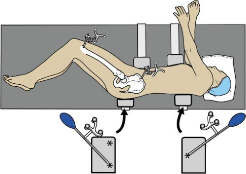 Figure 78.1. Patient is properly secured with two padded chest and pelvic supports in the lateral position. To register the longitudinal axis of body, the pointer guide is touched at three points (asterisks) on posterior supports, two on posterior pelvic supports and one on the chest support in a manner that the three points form a triangle. |
Related posts:


Stay updated, free articles. Join our Telegram channel

Full access? Get Clinical Tree


