:

(6.1)
 and ends at time
  by calculating the jerk cost:
(6.2)
 , velocity
  and acceleration
  are to be achieved when starting with the initial position
  , velocity
  and acceleration

(6.3)
The minimum of this function is found using calculus of variations. First, a function (6.4) is defined for a trajectory x where  is an arbitrary function such that
  ,
,  ,
,  .
.

 is an arbitrary function such that
  ,
,  ,
,  .
.
(6.4)
Let

The condition for the trajectory x to minimise I is given as:

Using integration by parts
![$$ \int\limits_{0}^{T} {{\dddot {x}}}_{t}\,{\dddot{\delta}}_{t}{\text{d}}t = \left. {{\dddot{x}}}_{t} {\ddot{\delta}}_{t}\right|_{0}^{T} - \int\limits_{0}^{T} {x_{t}^{[4]}
{\ddot{\delta}}_{t} {\text{d}}t} $$](/wp-content/uploads/2016/09/A313541_1_En_6_Chapter_Equ7.gif)
Using integration by parts again
![$$ - \int\limits_{0}^{T} {x_{t}^{\left[ 4 \right]} \ddot{\delta }_{t} {\text{d}}t = \left. { - x_{t}^{\left[ 4 \right]} \dot{\delta }_{t} } \right|_{0}^{T} + \int\limits_{0}^{T} {x_{t}^{[5]} \dot{\delta }_{t} {\text{d}}t} } $$](/wp-content/uploads/2016/09/A313541_1_En_6_Chapter_Equ8.gif)
Thus to satisfy the condition in (6.6), it is required that
![$$ \int\limits_{0}^{T} {x_{t}^{[6]} \delta_{t} {\text{d}}t = 0} $$](/wp-content/uploads/2016/09/A313541_1_En_6_Chapter_Equ9.gif)
This must apply for arbitrary functions  therefore for all
 ![$$ t \in [0,T] $$](/wp-content/uploads/2016/09/A313541_1_En_6_Chapter_IEq15.gif)
![$$ x_{t}^{[6]} = 0 $$](/wp-content/uploads/2016/09/A313541_1_En_6_Chapter_Equ10.gif)
In other words, the minimum jerk trajectory occurs when the sixth-time derivative of the trajectory function x is equal to zero. The general solution of this equation is a fifth-order polynomial in time (6.11), where  and
and  are six constants to be determined.


(6.5)

(6.6)
![$$ \int\limits_{0}^{T} {{\dddot {x}}}_{t}\,{\dddot{\delta}}_{t}{\text{d}}t = \left. {{\dddot{x}}}_{t} {\ddot{\delta}}_{t}\right|_{0}^{T} - \int\limits_{0}^{T} {x_{t}^{[4]}
{\ddot{\delta}}_{t} {\text{d}}t} $$](/wp-content/uploads/2016/09/A313541_1_En_6_Chapter_Equ7.gif)
(6.7)
![$$ - \int\limits_{0}^{T} {x_{t}^{\left[ 4 \right]} \ddot{\delta }_{t} {\text{d}}t = \left. { - x_{t}^{\left[ 4 \right]} \dot{\delta }_{t} } \right|_{0}^{T} + \int\limits_{0}^{T} {x_{t}^{[5]} \dot{\delta }_{t} {\text{d}}t} } $$](/wp-content/uploads/2016/09/A313541_1_En_6_Chapter_Equ8.gif)
(6.8)
![$$ \int\limits_{0}^{T} {x_{t}^{[6]} \delta_{t} {\text{d}}t = 0} $$](/wp-content/uploads/2016/09/A313541_1_En_6_Chapter_Equ9.gif)
(6.9)
 therefore for all
 ![$$ t \in [0,T] $$](/wp-content/uploads/2016/09/A313541_1_En_6_Chapter_IEq15.gif)
![$$ x_{t}^{[6]} = 0 $$](/wp-content/uploads/2016/09/A313541_1_En_6_Chapter_Equ10.gif)
(6.10)
 and
and  are six constants to be determined.
(6.11)

(6.12)

(6.13)
The first three constants are obtained from the initial conditions 


The last three constants are determined from the terminal conditions 


In matrix form
![$$ \left[ {\begin{array}{*{20}c} {x_{T} - a_{0} - a_{1} T - a_{2} T^{2} } \\ {\dot{x}_{T} - a_{1} - 2a_{2} T} \\ {{\ddot{\textit{x}}}_{T} - 2a_{2} } \\ \end{array} } \right] = \left[ {\begin{array}{*{20}c} {T^{3} } & {T^{4} } & {T^{5} } \\ {3T^{2} } & {4T^{4} } & {5T^{5} } \\ {6T} & {12T^{2} } & {20T^{3} } \\ \end{array} } \right]\left[ {\begin{array}{*{20}c} {a_{3} } \\ {a_{4} } \\ {a_{5} } \\ \end{array} } \right] $$](/wp-content/uploads/2016/09/A313541_1_En_6_Chapter_Equ20.gif)
![$$ \left[ {\begin{array}{*{20}c} {a_{3} } \\ {a_{4} } \\ {a_{5} } \\ \end{array} } \right] = \left[ {\begin{array}{*{20}c} {T^{3} } & {T^{4} } & {T^{5} } \\ {3T^{2} } & {4T^{4} } & {5T^{5} } \\ {6T} & {12T^{2} } & {20T^{3} } \\ \end{array} } \right]^{ - 1} \left[ {\begin{array}{*{20}c} {x_{T} - a_{0} - a_{1} T - a_{2} T^{2} } \\ {\dot{x}_{T} - a_{1} - 2a_{2} T} \\ {{\ddot{\textit{x}}}_{T} - 2a_{2} } \\ \end{array} } \right] $$](/wp-content/uploads/2016/09/A313541_1_En_6_Chapter_Equ21.gif)
The six constants are then substituted into (6.11), (6.12) and (6.13) to obtain the minimum jerk trajectory in position, velocity and acceleration, respectively.


(6.14)

(6.15)

(6.16)


(6.17)

(6.18)

(6.19)
![$$ \left[ {\begin{array}{*{20}c} {x_{T} - a_{0} - a_{1} T - a_{2} T^{2} } \\ {\dot{x}_{T} - a_{1} - 2a_{2} T} \\ {{\ddot{\textit{x}}}_{T} - 2a_{2} } \\ \end{array} } \right] = \left[ {\begin{array}{*{20}c} {T^{3} } & {T^{4} } & {T^{5} } \\ {3T^{2} } & {4T^{4} } & {5T^{5} } \\ {6T} & {12T^{2} } & {20T^{3} } \\ \end{array} } \right]\left[ {\begin{array}{*{20}c} {a_{3} } \\ {a_{4} } \\ {a_{5} } \\ \end{array} } \right] $$](/wp-content/uploads/2016/09/A313541_1_En_6_Chapter_Equ20.gif)
(6.20)
![$$ \left[ {\begin{array}{*{20}c} {a_{3} } \\ {a_{4} } \\ {a_{5} } \\ \end{array} } \right] = \left[ {\begin{array}{*{20}c} {T^{3} } & {T^{4} } & {T^{5} } \\ {3T^{2} } & {4T^{4} } & {5T^{5} } \\ {6T} & {12T^{2} } & {20T^{3} } \\ \end{array} } \right]^{ - 1} \left[ {\begin{array}{*{20}c} {x_{T} - a_{0} - a_{1} T - a_{2} T^{2} } \\ {\dot{x}_{T} - a_{1} - 2a_{2} T} \\ {{\ddot{\textit{x}}}_{T} - 2a_{2} } \\ \end{array} } \right] $$](/wp-content/uploads/2016/09/A313541_1_En_6_Chapter_Equ21.gif)
(6.21)
Figure 6.1 shows an example of the minimum jerk trajectory for the 1-DOF elbow joint. In this example, the joint starts in a stationary position and rotates for 2 s to stop at the 90° position.
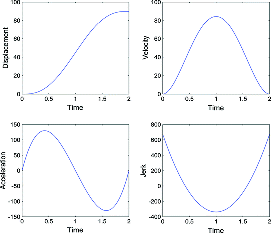

Fig. 6.1
Trajectory graphs in displacement, velocity, acceleration and jerk for the minimum jerk trajectory of the 1-DOF elbow joint moving from 0 to 90° in 2 s with a stationary start and end
6.1.2 Trajectories for the Shoulder
The minimum jerk trajectory is calculated for the human user’s upper limb joints since the goal was to achieve smooth movement for the user. For the 5-DOF exoskeleton, this includes the 3-DOF shoulder joint and 1-DOF elbow joint. Deriving trajectories for the elbow joint are straightforward since the movement of the exoskeleton’s Joint 5 translates directly to movements of the elbow joint. In addition, the movement of Joint 4 also translates well to movements of shoulder axial rotation. As a result, minimum jerk trajectory can be calculated directly for these two exoskeleton joints which will translate to minimum jerk trajectory movement for the respective human limb joints.
This is not the case for Joints 1, 2 and 3 in the 4R mechanism which are used to control the spherical position of the user’s upper arm in 2-DOF. The nonlinear relationship between the motion of the shoulder joint and the 4R mechanism means that even if the three exoskeleton joints are moving in their minimum jerk trajectories, the user’s shoulder joint will in most cases not be moving in its minimum jerk trajectory. Figures 6.2 and 6.3 illustrate this nonlinear relationship where the human shoulder is moving with constant angular velocity while Joints 1, 2 and 3 of the exoskeleton are required to follow a nonlinear trajectory in order to match the upper arm movement.
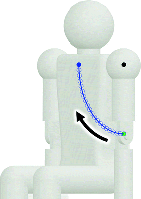


Fig. 6.2
A 90° flexion of the shoulder joint from the lowered vertical position to the horizontal forward position in 2 s with constant velocity. The solid green point indicates the starting position of the upper arm and the solid blue point indicates the ending position. Each hollow point in the trajectory path represents a 0.1-s time step

Fig. 6.3
A constant velocity flexion of the shoulder joint is shown in the top graph with the corresponding trajectories for exoskeleton Joints 1, 2 and 3 shown in the bottom three graphs. The relationship between shoulder movement and movement of exoskeleton joints is nonlinear
To achieve smooth movement of the shoulder, the minimum jerk trajectory must be computed for the 2-DOF shoulder movement (with axial rotation excluded) then converted to the respective trajectories of Joints 1, 2 and 3. These 2-DOF generate the spherical movement of the shoulder in 3D space and is typically described using a sequence of two Euler rotations. However, there are two problems with using Euler rotations to define a trajectory. First, singularities can occur in Euler rotations. Secondly, unlike for translations in 3D space, rotations in 3D space are not commutative so the order in which the two Euler rotations are applied affects the outcome. This is fine when defining a spherical coordinate in 3D space but it is not suitable for defining a spherical trajectory since information on the path of the trajectory is required. The two Euler rotations represent the target position relative to the starting position but since they are not commutative, the two rotations cannot be applied simultaneously to find a direct trajectory path between the two positions.
Instead of using Euler rotations, the minimum jerk trajectory is derived for a single rotation of the upper arm from the starting position to the target position. The travel distance of the single rotation is the angle between the two positions about the ICOR. First, the minimum jerk trajectory is computed for the one-dimensional travel angle using the given travel time. The trajectory obtained represents the angular displacement from the starting position towards the target position over time. Using Quaternion rotation, these angular displacements are then used to rotate from the starting position about the rotation axis to find the upper arm positions for each instance in time. As a result, a set of upper arm positions over time is obtained which represents the minimum jerk trajectory.
Next, the set of upper arm positions are converted to a respective set of Joint 1, 2 and 3 angles representing configurations of the 4R mechanism. However, the 4R mechanism is kinematically redundant; therefore, there are infinite configuration solutions that can achieve each upper arm position. To overcome this, an optimal 4R configuration has previously been identified for 89 upper arm positions in the workspace. These 89 optimal configurations are each represented by a Joint 1 angle value and its respective upper arm position. The Joint 1 angle eliminates the redundancy in the mechanism and enables a configuration solution to be found via inverse kinematics. Inverse kinematics is performed using the modified FABRIK algorithm to compute the angles of Joints 2 and 3.
It is very likely that the upper arm position of interest is not among the 89 obtained during design optimisation. In order to find the Joint 1 angle for an arbitrary upper arm position, the 89 sets of upper arm positions and their respective Joint 1 angles are interpolated. Natural neighbour interpolation is used to interpolate the scattered 3D data and estimate the value of Joint 1 angle for the given spherical coordinate of the upper arm position. In this interpolation method, the scattered data points are tessellated to form a network of tetrahedra using the Delaunay criterion. These tetrahedra are used to define a network of Thiessen polyhedra (3D versions of a polygon) in a 3D Voronoi diagram. The polyhedra have all surfaces equidistant to two or more neighbouring points. For a given input, natural neighbour interpolation finds the points closest to this input among the scattered data. A Thiessen polyhedra is also constructed for the input point with respect to its neighbouring points. Weights are then applied to each neighbour point based on the proportion of overlap between the volume of the new input polyhedra and the volume of each neighbour’s initial polyhedra. These weights are applied to their respective neighbour points to interpolate an output value for the given input values. This ensures the interpolated output will be within the range of the neighbour points.
Now, the desired upper arm position and the interpolated Joint 1 angle are used to derive the angles of Joints 2 and 3 through inverse kinematics with the modified FABRIK algorithm. Once this is done, the angles of Joints 1, 2 and 3 are determined for a given upper arm position. This process is repeated for the upper arm positions in each time step of the minimum jerk trajectory to obtain a corresponding set of angles for Joints 1, 2 and 3. These sets of angles represent the simultaneous trajectories required from the three exoskeleton joints to achieve the minimum jerk trajectory of the upper arm in moving to the specified target position in the specified travel time. An example is shown in Figs. 6.4 and 6.5 where a minimum jerk trajectory of the upper arm is presented along with the corresponding trajectories of Joints 1, 2 and 3.
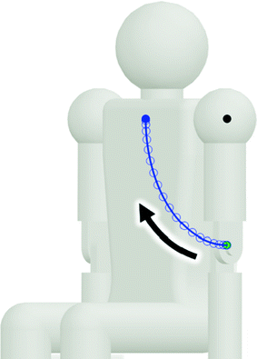
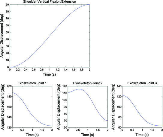

Fig. 6.4
A 90° flexion of the shoulder joint from the lowered vertical position to the horizontal forward position in 2 s with minimum jerk. Note that the points near the starting and stopping positions are denser which indicate the acceleration and deceleration of the upper arm in the minimum jerk trajectory

Fig. 6.5
A minimum jerk trajectory of shoulder flexion from 0° (upper arm positioned downwards) to 90° (upper arm positioned forwards) is shown in the upper graph. The corresponding trajectories for exoskeleton Joints 1, 2 and 3 are shown in the lower three graphs
6.2 Combining a Sequence of Movements
However, if the minimum jerk trajectory is found for each path independently using zero starting and terminal velocities and accelerations, the joint will stop at each target position. To obtain a smooth trajectory, the position, velocity and acceleration should be continuous throughout the entire trajectory. Therefore, each sub-trajectory should smoothly follow through to the next while passing through each target position at the target times without stopping. To achieve this, it is necessary to approximate the velocity and acceleration at the transition where one sub-trajectory ends and the next sub-trajectory begins. This transition velocity and acceleration is used as the terminal velocity and acceleration in the derivation of the minimum jerk trajectory for the initial sub-trajectory i and used as the starting velocity and acceleration in the derivation of the subsequent sub-trajectory  .
.
 .
.6.2.1 Cubic Spline Interpolation
The transition velocities and accelerations are obtained by approximating the entire trajectory using a cubic spline interpolation. The entire set of trajectory positions is fitted with a piecewise cubic spline that passes through all the points while minimising bending. Each point-to-point segment is approximated by a polynomial that ensures continuity between segments. Polynomials of order 3 or higher are required to achieve continuity, hence the use of a cubic spline. For n points in the trajectory, there are  intervals between them. A cubic polynomial is determined for each interval (6.22), where
  is the polynomial segment between point i and
  , and
, and  ,
,  ,
,  and
and  are the polynomial coefficients.

 intervals between them. A cubic polynomial is determined for each interval (6.22), where
  is the polynomial segment between point i and
  , and
, and  ,
,  ,
,  and
and  are the polynomial coefficients.
(6.22)
For the spline to pass through both the desired points, the following constraints are enforced for this segment:


In addition, to ensure each segment continues smoothly into the next segment, each segment must satisfy the following:


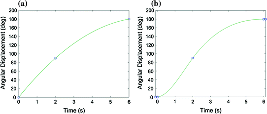
The trajectory should have a stationary start point and end point, but this is not the case for the cubic spline generated in MATLAB. This is illustrated in the example shown in Fig. 6.6 where a joint starts at 0°, moves to the 90° position at 2 s and arrives at the 180° position at 6 s. This represents a 180° movement over 6 s with a higher velocity at the start of the trajectory followed by a lower velocity later on. The “spline” function in MATLAB creates a “natural spline” which results in a straight line at both the start and the end of the spline where  is zero and
  is constant. However, to achieve a stationary point
  should be zero. To enforce this, an extra point is added slightly before the first point at the same position and another is added slightly after the final point at the same position. These additional points ensure the cubic spline will start and end with near-zero velocity. The two points are removed once the cubic spline is generated.

(6.23)

(6.24)

(6.25)

(6.26)
 is zero and
  is constant. However, to achieve a stationary point
  should be zero. To enforce this, an extra point is added slightly before the first point at the same position and another is added slightly after the final point at the same position. These additional points ensure the cubic spline will start and end with near-zero velocity. The two points are removed once the cubic spline is generated.
Fig. 6.6
Application of stationary end points. Trajectory plan to move the joint from 0° at 0 s to 90° at 2 s and 180° at 6 s. a Cubic spline interpolation of the three points. b Cubic spline interpolation with points added slightly before the start of the trajectory and slightly after the end of the trajectory to create stationary start and end points
The velocity and acceleration at each intermediate point in the cubic spline is used as the boundary conditions for computing the minimum jerk trajectories for each interval. Figure 6.7 shows an example of a multi-point trajectory where each point-to-point segment is a minimum jerk trajectory derived using the boundary conditions obtained from the cubic spline interpolation. The trajectory starts at 0° and passes the 30° position at 1 s, the 60° position at 2.5 s and the 90° position at 3.5 s. This represents a 90° movement over 3.5 s with a high velocity at the start of the trajectory, followed by a decreased velocity, and then a higher velocity again before arriving at the 90° position.
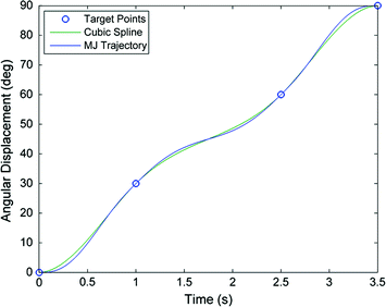

Fig. 6.7
Smooth trajectory for a multi-point trajectory plan. Plot of the target points, the cubic spline interpolation of these points with a stationary start and end, and the trajectory obtained by combining three minimum jerk trajectories (one between each pair of points) using velocity and acceleration boundary conditions obtained from the cubic spline interpolation
A pause in the trajectory can be achieved by setting two target points in the same position with the second point delayed by the desired pause time (see Fig. 6.8). The transition velocity and acceleration are zero at the starting and ending points of the pause.
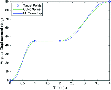

Fig. 6.8
Trajectory with a pause. Trajectory plan to move the joint from 0° at 0 s to 45° at 1 s, stay at 45° until 2 s and move to 90° at 4 s. Plot of the target points, the cubic spline interpolation and the trajectory obtained by combining three minimum jerk trajectories
6.2.2 Trajectories with Reversing Movement
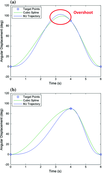
The cubic spline interpolation can cause an overshoot in the trajectory when the direction of movement is reversed. This overshoot in the cubic spline will translate to an overshoot in the final trajectory obtained using the minimum jerk criterion. An overshoot can occur either before or after an intermediate point where the target positions before and after this point are positioned in the same direction with respect to the intermediate point. A trajectory overshoot is not desirable since the joint moves further than the planned peak position. An example of an overshoot occurrence is shown in Fig. 6.9b where the trajectory plan in Fig. 6.9a is used. The joint starts at the 0° position and arrives at the 90° position at 4 s then returns to the 0° position at 6 s. This represents a movement to the 90° position followed by a faster reverse movement to return to the initial 0° position. Typically, when a trajectory that reverses upon arriving at a target position is set in the trajectory plan, the extreme target position is the furthest position the programmer wishes the joint to reach. For this reason, an overshoot should be prevented in all cases when a velocity reversal occurs.

