Fig. 5.1
Process diagram of the NSGA II algorithm
1.
[Start] Select a termination criterion based on number of iterations.
2.
[Initialize] Initialize a random population of Q chromosomes (suitable solutions).
3.
[Fitness] Evaluate the values of various objectives for each chromosome in the population.
4.
[Rank] Classify population into fronts using non-dominating sorting algorithm and assign non-domination ranks to each solution.
5.
[Offspring] For the first iteration, create a duplicate copy of the parent population by randomly arranging its solutions and call this offspring population.
6.
[Selection] Combine offspring with the parent population and select Q solutions based on non-domination rank. Call the resulting population as parents.
7.
[Crossover] Crossover the parents with a crossover probability to form new offspring.
8.
[Mutation] Mutate the new offspring with a chosen mutation probability.
9.
[Rank] Evaluate solutions for their objective values to perform non-dominated sorting and once again classify the population into fronts based on their non-domination ranks.
10.
[Check] Check for the termination criteria and stop if this is achieved else go to Step 6.
11.
[End] Stop and return the final population when the termination criterion is reached.
A kinematically redundant 4R mechanism can avoid the undesirable singular configurations that can occur with a 3R mechanism and achieve good performance in the entire shoulder workspace. The goal was to optimise the 4R mechanism to ensure the additional DOF provided by the redundant joint is efficiently utilised to achieve a high performance in a shoulder. This involves finding an optimal 4R design and also a set of optimal joint configurations for the mechanism [4].
The redundant joint in the 4R mechanism allows flexibility in the 4R linkage design. Whereas a 3R mechanism requires all link angles to be 90° in order to achieve the full spherical workspace, the link angles of the redundant 4R mechanism can have a variety of sizes and still achieve the full spherical workspace. Hence, there are a range of possible 4R mechanism designs that can be used in a shoulder exoskeleton. The 4R design can have variations in the sizes of the three link angles and the location of the base joint as shown in Fig. 5.2.
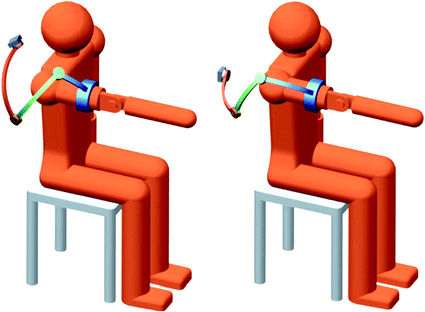
Fig. 5.2
Example of two different 4R designs with different link angle sizes and base joint position
In addition, an issue arising from the redundancy is that it is possible to achieve the same end-effector position with a range of different 4R configurations as shown in Fig. 5.3, i.e. there are infinite inverse kinematics solutions. Therefore, it is also necessary to identify the optimal joint configuration for reaching any given end-effector position in the shoulder workspace. The NSGA II algorithm is used to solve this complex nonlinear optimisation problem.
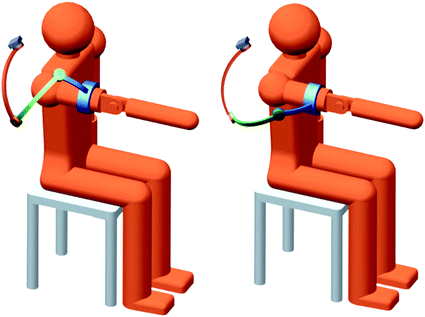
Fig. 5.3
Example of two different joint configurations of the same 4R design which both achieve the same end-effector position
Six variables are used in this optimisation problem. Descriptions for these variables and their permitted values are shown in Table 5.1. The first five variables describe the design of the 4R mechanism, where  and
and  describe the three link angles and
  and
and  describe the position of the base joint relative to the user’s shoulder in spherical coordinates. Here,
  precedes
  in the sequence of Euler rotations and the default position is directly above the user’s right shoulder. The sixth variable
  is used to determine the optimal joint configurations of the 4R mechanism. This variable is the angle of Joint 1 (
 ) when the end-effector is at the centre of the shoulder workspace. These three latter variables are illustrated in Fig. 5.4. A given value of
  is necessary because there are infinite possible joint configurations for achieving a given end-effector position due to the kinematic redundancy. If
  is known, the angular positions of the remaining joints required to achieve the given end-effector position can be determined from inverse kinematics. However, this only gives the configuration for reaching one position in the workspace. Therefore, an expanding algorithm is developed to compute the joint configurations for reaching the remaining workspace.
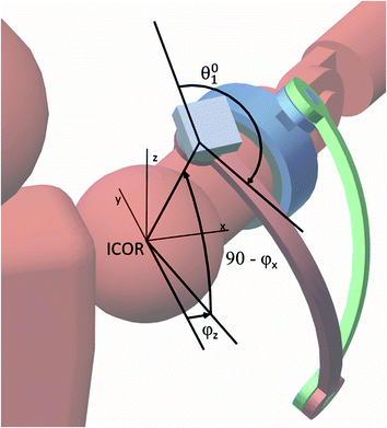
and describe the three link angles and and describe the position of the base joint relative to the user’s shoulder in spherical coordinates. Here, precedes in the sequence of Euler rotations and the default position is directly above the user’s right shoulder. The sixth variable is used to determine the optimal joint configurations of the 4R mechanism. This variable is the angle of Joint 1 () when the end-effector is at the centre of the shoulder workspace. These three latter variables are illustrated in Fig. 5.4. A given value of is necessary because there are infinite possible joint configurations for achieving a given end-effector position due to the kinematic redundancy. If is known, the angular positions of the remaining joints required to achieve the given end-effector position can be determined from inverse kinematics. However, this only gives the configuration for reaching one position in the workspace. Therefore, an expanding algorithm is developed to compute the joint configurations for reaching the remaining workspace.Table 5.1
Optimisation variables
Variable | Description | Permitted value (°) |
|---|---|---|
 | Angle size of link 1 | 20–160 |
 | Angle size of link 2 | 20–160 |
 | Angle size of link 3 | 20–160 |
 | Spherical coordinate of Joint 1 location about z-axis | −45 to 45 |
 | Spherical coordinate of Joint 1 location about x-axis | −90 to 90 |
 | Joint 1 angle when the end-effector is at the workspace centre | −180 to 180 |
Fig. 5.4
Illustration of the optimisation variables  and
and 
and The NSGA II algorithm produces a population of solutions, each with a value for the six variables within their permitted ranges. Each iteration of the algorithm improves these solutions until a set of Pareto optimal solutions are obtained.
In this optimisation problem, achieving the entire human shoulder workspace without mechanical interference is considered to be a compulsory objective. The other performance objectives are average joint motion, global condition number and maximum condition number. The NSGA II algorithm uses these three performance objectives to evaluate each solution that can reach the entire shoulder workspace and the best performing solutions are selected for producing the next generation of solutions. These objectives are discussed in the subsequent sections.
5.1.2 Workspace of the 4R Mechanism
The 4R mechanism is intended for a shoulder exoskeleton; therefore, the workspace of the human shoulder needs to be considered during optimisation. The workspace for the human shoulder is approximately half of the spherical workspace (i.e. a semi-sphere) while the 4R exoskeleton can be designed to operate the end-effector in the entire spherical workspace.
The semi-spherical shoulder workspace is discretised into points, each indicating an end-effector position to be analysed. A common method for allocating points on the surface of a sphere is by using the longitude and latitude parameters. However, this method results in a non-uniform distribution of points with a higher density of points at the two poles of the sphere. This causes the performance near the poles to have a larger influence on the overall performance score. Ideally, the points should be uniformly distributed to ensure the workspace is analysed evenly. A set of 89 uniformly distributed points over the semi-spherical workspace is generated using an algorithm proposed by Teanby [5]. This algorithm performs repeated subdivisions of a spherical icosahedron to obtain an increasingly dense grid of evenly distributed points on the surface of a sphere. Figure 5.5 shows the spheres from two consecutive subdivisions.
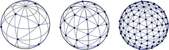
Fig. 5.5
Illustration of two consecutive subdivisions of a spherical icosahedron [5]. The black dots represent evenly distributed points on the surface of a sphere
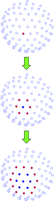
A sphere of 162 points is selected for representing the end-effector positions as this has a sufficient point density to provide a good representation of the 4R performance over the workspace. Since only the shoulder workspace is required rather than the entire spherical workspace, only 89 of the 162 points are used. These points cover a semi-spherical region in the lateral-anterior region of the user’s shoulder as shown in Fig. 5.6.
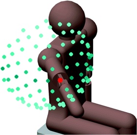
Fig. 5.6
The semi-spherical shoulder workspace is discretised into 89 uniformly distributed points for analysis. The model user shown has a shoulder posture at the centre of the workspace, represented by a red point
4R joint configurations are assessed for each of the 89 end-effector positions. The optimal joint configurations to reach each of the 89 end-effector positions are determined. Interpolation can then be used to find the joint configuration to reach any arbitrary end-effector position in the shoulder workspace.
The workspace of the 4R mechanism is limited by three factors. If any of these three cases occur with all possible joint configurations for an end-effector position, the end-effector position is considered unreachable. The first case occurs when there is no inverse kinematics solution for the given end-effector position and Joint 1 angle. This occurs when the end-effector cannot reach the position with the given link dimensions. The second case occurs when the joint configuration is at or very close to a singular configuration. Since there are significant limitations in operating at a singular configuration, the end-effector position that causes the singular configuration cannot be included into the robot workspace. The final case occurs when a part of the 4R structure is required to enter a forbidden region to reach an end-effector position. These include regions that can harm or cause discomfort for the user or cause mechanical interference between different parts of the exoskeleton system.
Therefore, the links must also not enter the user’s anterior region. End-effector positions that require the links to enter the user’s medial or anterior regions are considered unreachable. The boundary for this region is specified by a vertical plane intersecting the ICOR with a normal axis in the anterior-medial direction, 45° from the anterior axis. In addition, the region near the head and torso is also forbidden, i.e. the region above and below the ICOR. This region is represented by a vertical cylindrical volume with an axis intersecting the ICOR. Figure 5.7 shows the boundary of the region which the 4R mechanism must not enter.
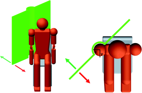
Fig. 5.7
Boundary of forbidden region for the 4R mechanism structure. The red arrow indicates the region that is forbidden and the green arrow indicates the permitted operating region
To identify whether the 4R mechanism enters the forbidden region, the locations of Joints 1, 2 and 3 are checked. Joint 4 is at the end-effector which is always located within the upper arm workspace due to the design; therefore, this joint will not cause any forbidden intrusions. To ensure the 4R mechanism does not enter the medial-anterior region of the user, the condition in (5.1) must be met, where  and
and  are, respectively, the x and y Cartesian coordinates of the location of joint j in the global coordinate system.
![$$ x_{j} > y_{j} \quad {\text{for}}\;\;j = 1,2,3 $$” src=”/wp-content/uploads/2016/09/A313541_1_En_5_Chapter_Equ1.gif”></DIV></DIV><br />
<DIV class=EquationNumber>(5.1)</DIV></DIV></DIV><br />
<DIV id=Par31 class=Para>Furthermore, the intrusion into the region above and below the shoulder ICOR is also forbidden and (<SPAN class=InternalRef><A href=]() 5.2) must also be satisfied, where d is the minimum allowable distance between a 4R joint and the vertical axis intersecting the shoulder ICOR.
5.2) must also be satisfied, where d is the minimum allowable distance between a 4R joint and the vertical axis intersecting the shoulder ICOR.
![$$ \sqrt {x_{j}^{2} + y_{j}^{2} } > d\quad {\text{for}}\;\;j = 1,2,3 $$” src=”/wp-content/uploads/2016/09/A313541_1_En_5_Chapter_Equ2.gif”></DIV></DIV><br />
<DIV class=EquationNumber>(5.2)</DIV></DIV></DIV><br />
<DIV id=Par32 class=Para>The coordinates of Joint 1, 2 and 3 with respect to the global coordinate system are derived using the DH transformation matrices of the 4R mechanism. Given that the coordinate systems are defined according to the DH notation and that the axes of rotation of all the joints intersect with the origin of the global coordinate system, the <SPAN class=EmphasisTypeItalic>z</SPAN>-axis of the local coordinate system at each joint indicates the direction the joint is located with respect to the global coordinate system. The normalised coordinates of the jth joint’s local <SPAN class=EmphasisTypeItalic>z</SPAN>-axis with respect to the global coordinate system can be obtained from (<SPAN class=InternalRef><A href=]() 5.3), where
5.3), where  and
and  are obtained from the DH matrix (5.4). Equations (5.1) and (5.2) are then used to check whether any joint lies in the forbidden region.
![$$ T_{j}^{0} = \left[ {\begin{array}{*{20}c} {\begin{array}{*{20}c} {n_{x} } & {o_{x} } & {a_{x} } \\ \end{array} } & {r_{x} } \\ {\begin{array}{*{20}c} {n_{y} } & {o_{y} } & {a_{y} } \\ {n_{z} } & {o_{z} } & {a_{z} } \\ 0 & 0 & 0 \\ \end{array} } & {\begin{array}{*{20}c} {r_{y} } \\ {r_{z} } \\ 1 \\ \end{array} } \\ \end{array} } \right] $$](/wp-content/uploads/2016/09/A313541_1_En_5_Chapter_Equ4.gif)
Get Clinical Tree app for offline access

and are, respectively, the x and y Cartesian coordinates of the location of joint j in the global coordinate system. and are obtained from the DH matrix (5.4). Equations (5.1) and (5.2) are then used to check whether any joint lies in the forbidden region.(5.3)
(5.4)
In addition, Joint 1 must not be positioned within the shoulder workspace. This is because the position of Joint 1 is fixed and positioning this joint inside the shoulder workspace will prevent the upper arm from entering this region of the workspace. Therefore, the location of Joint 1 is restricted to a region behind the shoulder joint. This is reflected in the ranges of  and
and  .
.
and .An expanding algorithm has been developed to obtain the optimal joint configurations for all 89 end-effector positions in the shoulder workspace while ensuring feasible joint transitions. This makes use of the value  which is generated by the NSGA II algorithm as the sixth variable. This variable is the
  value for reaching the end-effector position at the centre of the shoulder workspace. The expanding algorithm firstly finds the optimal joint configuration for this centre position using the six variable values of the solution provided by the NSGA II algorithm. The algorithm then computes the optimal joint configurations for all the end-effector positions adjacent to this starting position. This is done while ensuring the transition between adjacent end-effector positions are realistic, requires minimal joint displacements, does not cause interference and avoids approaching a singular configuration. This is achieved by generating a range of
  values for the adjacent child position which are within 20° of the parent positions’
  value and analysing the performance of their respective joint configurations. The
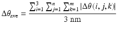
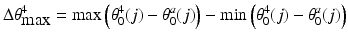
  value that gives the best performing joint configuration is then selected as the optimal for the child end-effector position. This is done for each end-effector position that is adjacent to the parent position and has not already been analysed. The process is then applied to the next layer of adjacent end-effector positions and is repeated until all 89 positions in the shoulder workspace have been investigated. Figure 5.8 shows the first two iterations of the expanding algorithm.
which is generated by the NSGA II algorithm as the sixth variable. This variable is the value for reaching the end-effector position at the centre of the shoulder workspace. The expanding algorithm firstly finds the optimal joint configuration for this centre position using the six variable values of the solution provided by the NSGA II algorithm. The algorithm then computes the optimal joint configurations for all the end-effector positions adjacent to this starting position. This is done while ensuring the transition between adjacent end-effector positions are realistic, requires minimal joint displacements, does not cause interference and avoids approaching a singular configuration. This is achieved by generating a range of values for the adjacent child position which are within 20° of the parent positions’ value and analysing the performance of their respective joint configurations. The value that gives the best performing joint configuration is then selected as the optimal for the child end-effector position. This is done for each end-effector position that is adjacent to the parent position and has not already been analysed. The process is then applied to the next layer of adjacent end-effector positions and is repeated until all 89 positions in the shoulder workspace have been investigated. Figure 5.8 shows the first two iterations of the expanding algorithm.Fig. 5.8
The first two iterations in the expanding algorithm. Each iteration finds the joint configurations for a new layer of end-effector positions. The red points represent the positions to be analysed in the current iteration and the blue points represent the positions that have already been analysed in a previous iteration
By starting from the centre end-effector position in the workspace, the expanding algorithm is completed with the minimum number of iterations. The overall ease of transition between every combination of adjacent end-effector positions is used as part of the average joint motion objective in the optimisation algorithm. This is calculated as the average change in joint angles between the joint configurations of every pair of adjacent end-effector positions  . The objective is to minimise (5.5), where
  is the change in joint angle of joint i in moving the end-effector from workspace position j to an adjacent position k, m is the number of end-effector positions adjacent to position j, and n is the total number of workspace positions.
. The objective is to minimise (5.5), where is the change in joint angle of joint i in moving the end-effector from workspace position j to an adjacent position k, m is the number of end-effector positions adjacent to position j, and n is the total number of workspace positions.(5.5)
The resulting set of 89  values which achieves optimal joint configurations for reaching the 89 end-effector positions will be used to control the kinematically redundant robot. Interpolation of the 89
  values can be done to find the optimal joint configuration for any arbitrary end-effector position in the shoulder workspace. This is achieved by interpolating the set of
  data to find the optimal
  value followed by inverse kinematics to compute the corresponding
  and
and  values. The joint angles obtained represent the optimal joint configuration for reaching the specified end-effector position.
values which achieves optimal joint configurations for reaching the 89 end-effector positions will be used to control the kinematically redundant robot. Interpolation of the 89 values can be done to find the optimal joint configuration for any arbitrary end-effector position in the shoulder workspace. This is achieved by interpolating the set of data to find the optimal value followed by inverse kinematics to compute the corresponding and values. The joint angles obtained represent the optimal joint configuration for reaching the specified end-effector position.In this research work, the range of motion of shoulder axial rotation is assumed to drift linearly up to 45° between the limits of horizontal flexion and extension. It is desirable to minimise the largest clockwise and counter-clockwise angular offset between the angular position of Joint 4 and the angular position of shoulder axial rotation that occurs in the workspace. A small maximum offset will mean that only a small additional range of motion is required for Joint 4 on top of the range of motion of shoulder axial rotation. The objective is to minimise (5.6), where  is the additional range of motion required for Joint 4,
  is the default angular position of Joint 4 at end-effector position j relative to the global coordinate system, and
  is the default angular position of shoulder axial rotation at upper arm position j relative to the global coordinate system.
is the additional range of motion required for Joint 4, is the default angular position of Joint 4 at end-effector position j relative to the global coordinate system, and is the default angular position of shoulder axial rotation at upper arm position j relative to the global coordinate system.(5.6)
5.1.3 Singularity Analysis
Singularity analysis is done using Jacobian matrices and its condition number which has often been used as measures of robot manipulability [6–8]. The Jacobian matrix of the robot maps the robot’s joint velocities to the angular velocity of the end-effector according to (5.7), where  is the angular velocity of the end-effector, J is the Jacobian matrix and
  is the joint velocity vector.

is the angular velocity of the end-effector, J is the Jacobian matrix and is the joint velocity vector.(5.7)
The Jacobian matrix for the 4R mechanism J is a 3 × 4 non-square matrix due to the redundant joint. Each column of J represents the relationship between the end-effector and one of the four revolute joints. (5.7) can be written as (5.8), where ![$$ J = \left[ {\begin{array}{*{20}c} {\begin{array}{*{20}c} {J_{1} } & {J_{2} } \\ \end{array} } & {\begin{array}{*{20}c} {J_{3} } & {J_{4} } \\ \end{array} } \\ \end{array} } \right] $$](/wp-content/uploads/2016/09/A313541_1_En_5_Chapter_IEq35.gif) and is a 3 × 4 matrix with
and is a 3 × 4 matrix with  , and
, and  representing the relationships between the angular velocity of the 4R end-effector
  and the angular rates
  and
and  of Joints 1, 2, 3 and 4, respectively.
![$$ \omega = \left[ {\begin{array}{*{20}c} {\begin{array}{*{20}c} {J_{1} } & {J_{2} } \\ \end{array} } & {\begin{array}{*{20}c} {J_{3} } & {J_{4} } \\ \end{array} } \\ \end{array} } \right]\left[ {\begin{array}{*{20}c} {\begin{array}{*{20}c} {\dot{\theta }_{1} } \\ {\dot{\theta }_{2} } \\ \end{array} } \\ {\begin{array}{*{20}c} {\dot{\theta }_{3} } \\ {\dot{\theta }_{4} } \\ \end{array} } \\ \end{array} } \right] $$](/wp-content/uploads/2016/09/A313541_1_En_5_Chapter_Equ8.gif)
and is a 3 × 4 matrix with , and representing the relationships between the angular velocity of the 4R end-effector and the angular rates and of Joints 1, 2, 3 and 4, respectively.(5.8)
Due to the spherical nature of the 4R mechanism and the assignment of the DH coordinate systems at the ICOR, the Jacobian for each joint i can be obtained with (5.9), where  and
and  are obtained from the DH transformation matrix (5.10).
![$$ J_{i} = \left[ {\begin{array}{*{20}c} {n_{z} } \\ {o_{z} } \\ {a_{z} } \\ \end{array} } \right]_{5}^{i} $$](/wp-content/uploads/2016/09/A313541_1_En_5_Chapter_Equ9.gif)
![$$ T_{5}^{i} = \left[ {\begin{array}{*{20}c} {\begin{array}{*{20}c} {n_{x} } & {o_{x} } & {a_{x} } \\ \end{array} } & {r_{x} } \\ {\begin{array}{*{20}c} {n_{y} } & {o_{y} } & {a_{y} } \\ {n_{z} } & {o_{z} } & {a_{z} } \\ 0 & 0 & 0 \\ \end{array} } & {\begin{array}{*{20}c} {r_{y} } \\ {r_{z} } \\ 1 \\ \end{array} } \\ \end{array} } \right] $$](/wp-content/uploads/2016/09/A313541_1_En_5_Chapter_Equ10.gif)
and are obtained from the DH transformation matrix (5.10).(5.9)
(5.10)
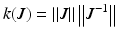
By definition, the condition number is given by (5.11), where  is the norm of the matrix [8].
is the norm of the matrix [8].