Minimally Invasive Transforaminal Lumbar Interbody Fusion
Reginald S. Fayssoux
Choll W. Kim
DEFINITION
Minimally invasive transforaminal lumbar interbody fusion (MIS TLIF) is a modification of the Wiltse exposure for decompression and interbody fusion of the motion segment using specialized retractor and instrumentation systems and fluoroscopic guidance to minimize the surgical corridor.
Standard TLIF is a well-established technique for decompression and fusion of a vertebral motion segment that uses a midline exposure to perform a unilateral facetectomy and exposure of Kambin triangle to access the disc space for interbody fusion.
TLIF, in comparison to standard posterolateral fusion, allows for improved fusion rates, indirect decompression via restoration of intervertebral disc height, and anterior column support without the need for an anterior retroperitoneal/transperitoneal exposure. The increased risk of neurologic injury to the exiting and traversing nerve roots with TLIF must be weighed against these advantages.
MIS TLIF, in comparison to standard open TLIF, is performed through small paramedian incisions and is typically coupled with minimally invasive posterior (ie, facet) fusion and instrumentation.1 Typically, formal posterolateral fusion is not done; consequently, MIS TLIF relies heavily on the interbody fusion for avoidance of pseudarthrosis and successful outcomes.
MIS TLIF has been shown to have less blood loss, earlier postoperative recovery, and decreased rates of infection in comparison to standard surgery.1,2,4 MIS TLIF may potentially have improved long-term outcomes as a result of the preservation of important musculotendinous attachments and the maintenance of integrity of the dorsolumbar fascia.3
MIS TLIF is much more reliant on fluoroscopic imaging guidance in comparison to standard TLIF, thus there is increased radiation exposure to the surgeon, staff, and patient. The amount of radiation exposure lessens with surgeon experience. Navigation with fluoroscopic or computed tomography (CT) imaging may allow for decreased radiation exposure to the surgeon and staff.
ANATOMY
Paraspinal Anatomy
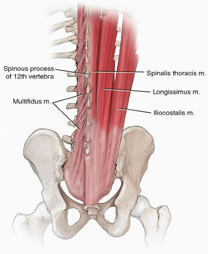
The lumbar multifidus muscle is a key stabilizer of the lumbar spine.4
Largest and most medial of the deep lumbar paraspinal musculature
Originates from the spinous process and inserts on the superior articular process of the vertebra one to two levels caudally (FIG 1)
Designed for short, powerful movements with maximum force generated during lumbar flexion to optimize its ability to stabilize the lumbar spine motion segments during movement
Detachment of the multifidus tendon with traditional midline laminectomy compromises multifidus function.
A paramedian approach, in contrast, preserves the multifidus tendon attachments.
Discectomy
Kambin triangle is an anatomic safe corridor to the intervertebral disc space bounded medially by the dural tube/traversing nerve root, laterally by the exiting nerve root, and caudally by the pedicle (FIG 2).
Exposure of Kambin triangle is accomplished by facetectomy. In the technique we described, a total facetectomy is performed. The inferior articular process is removed; however, the pars is maintained (to protect the dorsal root ganglion on cage insertion). The superior articular process is removed up to the cranial aspect of the pedicle.
The exiting nerve root hugs the medial and inferior border of its associated pedicle. The sensitive dorsal root ganglion typically lies inferior to the pedicle.
Pedicle Screw Placement
Percutaneous pedicle screw placement requires understanding the topographic anatomy of the posterior elements as well as the radiographic projection of the pedicle on various radiographic views.
The anatomic starting point for pedicle screw placement is typically at the intersection of a horizontal line that bisects the transverse process and a vertical line at or just lateral to the lateral aspect of the pars. The upslope of the facet-transverse process junction is a palpable anatomic landmark.
The more lateral the starting point, the more medial angulation is needed. This can be problematic in a patient with a narrow pelvis as the posterior iliac crests can limit the ability to medialize pedicle screw tracts.
The more medial the starting point, the greater the risk of facet violation.
The radiographic starting point for pedicle screw placement is typically at the lateral aspect of the radiographic pedicle. At the low lumbar spine, because of medial pedicle angulation, an anatomic starting point may be preferred, which may not necessarily coincide with the lateral aspect of the radiographic pedicle.
The radiographic pedicle correlates with the anatomic isthmus of the pedicle for hourglass-shaped pedicles. In the lower lumbar spine, where the pedicles are more cylindrical (ie, without an isthmus) and medially angulated, the anatomic correlate of the radiographic pedicle is less clear.
Pedicles are oriented sagittally at the thoracolumbar junction and angulate progressively medial as one moves caudally. At S1, the pedicles typically project more than 20 degrees medial.
PATIENT HISTORY AND PHYSICAL FINDINGS
Earlier postoperative recovery with MIS TLIF is advantageous in elderly patients.
Patients with severe osteoporosis are not ideal candidates for MIS TLIF because of the difficulty in avoiding endplate violation and subsequent graft subsidence.
MIS TLIF is challenging in obese patients because of the difficulty in obtaining good radiographic imaging and the difficulty in manipulating instruments through a long working corridor. The advantages in terms of postoperative recovery, however, are most apparent in obese patients as the difference in the extent of soft tissue dissection between MIS and standard techniques is greatest.
MIS TLIF can be a useful consideration in patients with previous midline surgery as dissection through scar tissue can be avoided. However, scar tissue from intracanal epidural bleeding at levels adjacent to previous surgery can complicate the exposure of Kambin triangle, and extension of previous pedicle screw instrumentation can be challenging.
IMAGING AND OTHER DIAGNOSTIC STUDIES
Pedicles should be evaluated radiographically prior to surgery to ensure that pedicle screw placement is feasible. If not, alternative means of fixation should be considered (eg, spinous process plate fixation).
A narrow pelvis (decreased distance between the posterior iliac crests) can make medial angulation of lower lumbar pedicle screws challenging. A more medial starting point with a straightforward pedicle screw trajectory or alternative means of fixation may need to be considered in these situations.
CT and magnetic resonance imaging (MRI) axial sections can be used to identify pedicle screw starting points and to approximate screw diameters and lengths.
Nerve root anomalies can be identified on preoperative imaging and, if unilateral, should prompt consideration for MIS TLIF exposure on the contralateral side. Alternative techniques that do not require nerve root retraction can also be considered (eg, standard posterolateral fusion without interbody, anterior fusion through an anterior, or lateral retroperitoneal exposure with posterior MIS fusion and instrumentation, etc).
TLIF, in general, should be pursued with care at the level of the cord or conus medullaris as the risk of significant neurologic injury is increased.
SURGICAL MANAGEMENT
Indications
One or two level lumbar pathology in the presence of the following:
Spinal stenosis with instability (eg, degenerative or isthmic spondylolisthesis)
Symptomatic degenerative disc disease
Relative contraindications
High-grade spondylolisthesis (Meyerding grade 3 or 4)
Severe osteoporosis
Nerve root anomalies
There are multiple methods of performing an MIS TLIF. The different techniques are similar with respect to the decompression and discectomy but can differ with respect to the method used for distraction of the disc space, the fusion technique used to supplement the interbody fusion, and the instrumentation used for stabilization of the motion segment.
The technique we described involves subtotal discectomy using interbody spacer trials to sequentially distract the disc space and contralateral facet fusion with bilateral pedicle screw placement.
Other methods using alternative techniques can be equally successful in properly selected patients.
The disc space can be distracted via the pedicle screws.
Posterior interlaminar or posterolateral bone graft can be used to supplement the interbody fusion.
Alternative means of posterior instrumentation/stabilization include unilateral pedicle screw placement, unilateral pedicle screw placement with a contralateral facet screw, unilateral pedicle screw placement with a spinous process plate, and isolated spinous process plate fixation.
Preoperative Planning
Patients should be evaluated for the following:
Osteoporosis
Potential issues with bone healing (nicotine use, diabetes mellitus, etc)
Previous surgery and the potential for epidural scarring
Obesity and retractor blade depth requirements
Need for contralateral decompression
Imaging should be evaluated for the following:
Mobility of the motion segment
Extent and nature of canal stenosis
Determines cranial/caudal extent of decompression
Need for osteophyte removal at the contralateral recess
Nerve root anomalies—best seen on T1-weighted axial imaging
Pedicle orientation, diameters, and pedicle screw lengths
Positioning
Patients are positioned prone on a radiolucent spine table. We prefer to position our patients using a Wilson frame attachment for the Jackson table to aid exposure of the interlaminar window and distraction of the motion segment. With release of the disc space and careful attention to the radiographic alignment, we have not found inadvertent fusion in kyphosis to be an issue.
Upper limbs are carefully positioned to avoid iatrogenic injury (eg, brachial plexus palsy, ulnar nerve compression, rotator cuff tendinitis).
Extension of the hips aids in obtaining lordotic alignment of the motion segment.
Flexion of the knees reduces root tension for the lower lumbar levels.
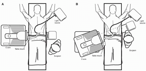
Room setup (FIG 3)
C-arm from opposite side of TLIF
This is a key point. With the C-arm coming in from the opposite side of the exposure, the C-arm base can be locked, and the boom can be “wagged” in and out of the field. This allows for frequent imaging and decreases the need for the surgeon to step out of the surgical field. This is especially critical in the initial phases of the learning curve when frequent imaging is prudent.
Table mount on opposite side of TLIF at level of hip
Light source on same side of TLIF
Imaging
Consistent terms for intraoperative fluoroscopic imaging help in obtaining reproducible imaging. We use the following:
Push in/out
Lean or tilt north/south (ie, toward the head/toward the feet)
Rainbow over/under
Move north/south
Wag north/south
Properly aligned anteroposterior (AP) and lateral images are crucial for the MIS TLIF technique. The best method for identifying the “perfect” image, in our opinion, is to sequentially image from “imperfect” to “perfect” back to “imperfect.”
TECHNIQUES
▪ Patient Positioning and Planning Incision Sites
AP positioning
The C-arm should start in a direct upright position (“90-90”).
The table should be rotated (“airplaned”) until a perfectly rotated image is obtained. The C-arm should then be tilted until level endplates are obtained. The C-arm should not be rainbowed.
A properly aligned AP image of the vertebral body should show the superior endplate as a single, dense line. The pedicles should be symmetric and located just below the superior endplate. The spinous process should be in the midline (although this can be misleading in the presence of scoliosis because of deformity of the spinous processes) (TECH FIG 1A).
A horizontal line at the back marking the disc space can be used to guide the orientation of the C-arm for a properly aligned lateral image.
Stay updated, free articles. Join our Telegram channel

Full access? Get Clinical Tree


