4 Methods of gait analysis
Visual gait analysis
1. It is transitory, giving no permanent record
2. The eye cannot observe high-speed events
3. It is only possible to observe movements, not forces
4. It depends entirely on the skill of the individual observer
5. It is subjective and it can be difficult to avoid assessor bias if the patient is undergoing treatment
6. Subjects may act differently when they know they are being watched (Hawthorne effect)
7. A clinic or laboratory environment may be very different than the real world.
In a study on the reproducibility of visual gait analysis, Krebs et al. (1985) found it to be ‘only moderately reliable’. Saleh and Murdoch (1985) compared the performance of people skilled in visual gait analysis with the data provided by a combined kinetic/kinematic system. They found that the measurement system identified many more gait abnormalities than had been seen by the observers.
Many clinicians include the observation of a subject’s gait as part of their clinical examination. However, this is not gait analysis if it is limited to watching the subject make a single walk, up and down the room. This merely gives a superficial idea of how well they walk and perhaps identifies the most serious abnormality. A thorough visual gait analysis involves watching the subject while he or she makes a number of walks, some of which are observed from one side, some from the other side, some from the front and some from the back. As the subject walks, the observer should look for the presence or absence of a number of specific gait abnormalities, such as those described in Chapter 3 and summarised in Table 4.1. A logical order should be used for looking for the different gait abnormalities – the mixture of walking directions listed in the table is not recommended! According to Rose (1983), it is also important, when performing visual gait analysis, to compare the ranges of motion at the joints during walking with those which are observed on the examination plinth – they may be either greater or smaller.
Table 4.1 Common gait abnormalities and best direction for observation
| Gait abnormality | Observing direction |
|---|---|
| Lateral trunk bending | Side |
| Anterior trunk bending | Side |
| Posterior trunk bending | Side |
| Increased lumbar lordosis | Side |
| Circumduction | Front or behind |
| Hip hiking | Front or behind |
| Steppage | Side |
| Vaulting | Side or front |
| Abnormal hip rotation | Front or behind |
| Excessive knee extension | Side |
| Excessive knee flexion | Side |
| Inadequate dorsiflexion control | Side |
| Abnormal foot contact | Front or behind |
| Abnormal foot rotation | Front or behind |
| Insufficient push off | Side |
| Abnormal walking base | Front or behind |
| Rhythmic disturbances | Side |
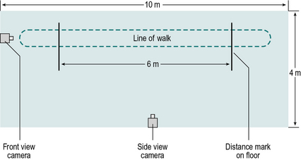
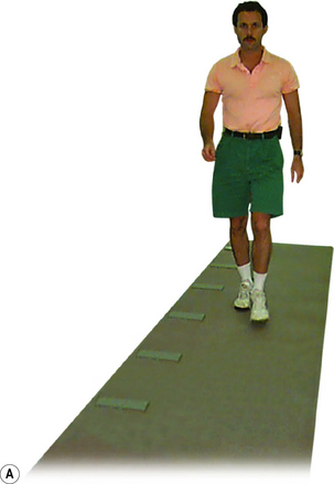
The minimum length required for a gait analysis walkway is a hotly debated subject. The authors believe that 8 m (26 ft) is about the minimum for use with fit young people, but that at least 12 m (39 ft) is preferable, since it permits fast walkers to ‘get into their stride’ before any measurements are made. However, shorter walkways are satisfactory for people who walk more slowly. This particularly applies to those with a pathological gait, since the gait pattern usually stabilises within the first two or three steps. A notable exception to this, however, is the gait in parkinsonism, which ‘evolves’ over the first few strides. The width required for a walkway depends on what equipment, if any, is being used to make measurements. For visual gait analysis, as little as 3 m (10 ft) may be sufficient. If video recording is being used, the camera needs to be positioned a little further from the subject and about 4 m (13 ft) is needed. A kinematic system making simultaneous measurements from both sides of the body normally requires a width of at least 5–6 m (16–20 ft). Figure 4.1 shows the layout of a small gait laboratory used for visual gait analysis, video recording and the measurement of the general gait parameters.
Some investigators permit subjects to choose their own walking speed, whereas others control the cycle time (number of steps in a set time) or the cadence (steps per minute), for example by asking them to walk in time with a metronome. The rationale for controlling the cadence is that many of the measurable parameters of gait vary with the walking speed and controlling this provides one means of reducing the variability. However, subjects are unlikely to walk naturally when trying to keep pace with a metronome, and patients with motor control problems may find it difficult or even impossible to walk at an imposed cadence. Zijlstra et al. (1995) found considerable differences in the gait of normal subjects between ‘natural’ walking and ‘constrained’ walking, in which the subject was required either to step in time with a metronome or to step on particular places on the ground. The answer to this dilemma is probably to accept the fact that subjects need to walk at different speeds and to interpret the data appropriately. This means that ‘normal’ values must be available for a range of walking speeds. An unresolved difficulty with this approach is that it may not be possible to get ‘normal’ values for very slow walking speeds, since normal individuals do not customarily walk very slowly and when asked to do so, some of the gait measurements become very variable (Brandstater et al., 1983).
Gait assessment
Simply observing the gait and noting abnormalities is of little value by itself. It needs to be followed by gait assessment, which is the synthesis of these observations with other information about the subject, obtained from the history and physical examination, combined with the intelligence and experience of the observer (Rose, 1983). Visual gait analysis is entirely subjective and the quality of the analysis depends on the skill of the person performing it. It can be an interesting exercise to perform visual gait analysis on people walking past in the street, but without knowing their clinical details it is easy to misinterpret what is wrong with them.
When performing any type of gait analysis, one thing that must be constantly borne in mind is that you are observing effects and not causes. Putting it another way, the observed gait pattern is not the direct result of a pathological process but the net result of a pathological process and the subject’s attempts to compensate for it. The observed gait pattern is ‘what is left after the available mechanisms for compensation have been exhausted’ (Rose, 1983).
Examination by video recording
1. It reduces the number of walks a subject needs to do
2. It makes it possible to show the subject exactly how they are walking
3. It makes it easier to teach visual gait analysis to someone else
4. It completes the picture in a gait report as seeing the patient is very meaningful while reading values of their analysis.
In making a thorough visual gait analysis without the use of video recording, the subject needs to make repeated walks to confirm or refute the presence of each of the gait abnormalities listed in Table 4.1. If the subject is in pain or easily fatigued, this may be an unreasonable requirement and it may be difficult to achieve a satisfactory analysis. The use of video recording permits the subject to do a much smaller number of walks, as the person performing the analysis can watch the recording as many times as necessary.
Individual investigators will find their own ways of performing gait analysis using video recording. A common routine used involves the subject being asked to wear shorts or a swim suit, so that the majority of the leg is visible. It is important that the subject should walk as ‘normally’ as possible, so they are asked to wear their own indoor or outdoor shoes, with socks if preferred. Unless it would unduly tire the subject, it is a good idea to make one or two ‘practice’ walks, before starting video recording. Two camera positions are often used, one viewing from the side (sagittal plane) and the front (coronal plane) (Fig. 4.1). These are first adjusted to show the whole body from head to feet and the subject is recorded as they walk the length of the walkway in one direction. At the end of the walkway, the subject turns around, with a rest if necessary, and is recorded as they walk back again. The whole process may then be repeated with the cameras adjusted to show a close-up of the body from the waist down, or of the body segment of interest.
It is often helpful to mark the subject’s skin, for example using an eyebrow pencil or whiteboard marker, to enhance the visibility of anatomical landmarks on the recording. Hillman et al. (1998) fitted subjects with surface-mounted ‘rotation indicators’, to improve the accuracy with which transverse plane rotations were estimated from video recording.
The analysis is performed by replaying the video recording, looking for specific gait abnormalities in the different views and interpreting what is seen in the light of the subject’s history and physical examination. It is particularly helpful if two or more people work together to perform the analysis. Rose (1983) suggested that gait analysis should be based on the team approach, with discussion and hypothesis testing. As will be described in Chapter 5, hypothesis testing may involve an attempted modification of the gait, for instance by fitting an orthosis or by paralysing a muscle using local anaesthesia.
Temporal and spatial parameters during gait
Temporal and spatial parameters of gait, sometimes referred to as the general gait parameters, include cycle time (or stride time), stride length and speed. These provide the simplest form of objective gait evaluation (Robinson and Smidt, 1981) and may be made using only a stopwatch and a tape measure. Other temporal and spatial parameters of gait include, step time, double support time, single support time, step length, base width and foot angle. However these measurements require the use of specialist equipment which will be described in the next section.
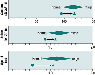
Cycle time, stride length and speed tend to change together in most locomotor disabilities, so that a subject with a long cycle time will usually also have a short stride length and a low speed (speed being stride length divided by cycle time). The general gait parameters give a guide to the walking ability of a subject, but little specific information. They should always be interpreted in terms of the expected values for the subject’s age and sex, such as those covered in Chapter 2. Figure 4.2 shows one way in which these data may be presented; the diamonds represent the 95% confidence limits for a normal subject of the same age and sex as the subject under investigation. Although cycle time is gradually replacing cadence in the gait analysis community, it is more convenient to use cadence on plots of this type, since abnormally slow gait will give values on the left-hand side of the graph for all three of the general gait parameters.


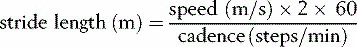
Stride length
Stride length can be determined in two ways: by direct measurement or indirectly from the speed and cycle time. The simplest direct method of measurement is to count the strides taken while the subject covers a known distance. More useful methods include putting ink pads on the soles of the subject’s shoes and walking on paper (Rafferty and Bell, 1995), using marker pens attached to shoes (Gerny, 1983) and a more messy option is to have the subject step with both feet in a shallow tray of talcum powder and then walk across a polished floor or along a strip of brown wrapping paper or coloured ‘construction paper’, leaving a trail of footprints. These may be measured, as shown in Figure 2.3, to derive left and right step lengths, stride length, walking base, toe out angle and some idea of the foot contact pattern. This investigation is able to provide a great deal of useful and surprisingly accurate information, for the sake of a few minutes of mopping up the floor afterwards! As an alternative to using talcum powder, felt adhesive pads, soaked in different coloured dyes, may be fixed to the feet (Rose, 1983). The subject walks along a strip of paper and leaves a pattern of dots, which give an accurate indication of the locations of both feet.

The equivalent calculation using cadence is:


Measurement of temporal and spatial parameters during gait
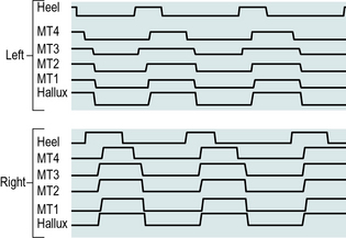
A number of systems have been described which perform the automatic measurement of the timing of the gait cycle, sometimes called the temporal gait parameters. Such systems may be divided into two main classes: footswitches and instrumented walkways. Figure 4.3 shows typical data, which could be obtained from either type of system.
Footswitches
Footswitches are used to record the timing of gait. If one switch is fixed beneath the heel and one beneath the forefoot, it is possible to measure the timing of initial contact, foot flat, heel rise and toe off, and the duration of the stance phase (see Figs 2.2 and 4.3). Data from two or more strides make it possible to calculate cycle time and swing phase duration. If switches are mounted on both feet, the single and double support times can also be measured. The footswitches are usually connected through a trailing wire to a computer, although alternatively either a radio transmitter or a portable recording device may be used to collect the data and transfer them to the measuring equipment.
Instrumented walkways
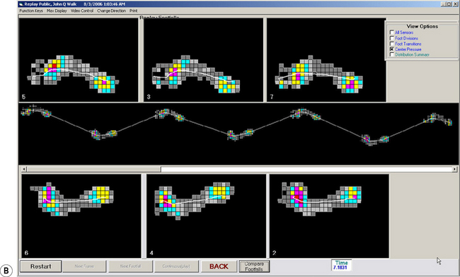
An alternative arrangement is to have the walkway itself contain a large number of switch contacts, which detect the position of the foot, as well as the timing of heel contact and toe off. This has the advantage that no trailing wires are required and the walkway can be used to measure both step lengths and the stride length. A number of commercial systems are available to make this type of measurement, often also providing some information on the magnitude of the forces between the foot and the ground. One such system, which is now in common use, is the ‘GAITRite’ (Bilney et al., 2003; Menz et al., 2004) (Fig. 4.4).
Camera-based motion analysis
General principles
To achieve reasonable accuracy in kinematic measurement, it is necessary to use a calibrated three-dimensional system, which involves making measurements from more than one viewpoint. A detailed review of the technical aspects of the three-dimensional measurement of human movement was given in four companion papers by Cappozzo et al. (2005), Chiari et al. (2005), Leardini et al. (2005) and Della Croce et al. (2005). Although there are considerable differences in convenience and accuracy between cine film, video recording, television/computer and optoelectronic systems, the data processing for the different types of three-dimensional measurement systems is similar.
All measurement systems, including the kinematic systems to be described, suffer from measurement errors. Measurement accuracy depends to a large extent on the field of view of the cameras, although it also differs somewhat between the different systems. The earlier systems had measurement errors of 2–3 mm in all three dimensions, throughout a volume large enough to cover a complete gait cycle (Whittle, 1982). Recently, design and (especially) calibration improvements have reduced typical errors to less than 1 mm. Some commercial systems claim to provide much higher accuracy than this, but the authors treat such claims with scepticism, particularly when applied to the measurement of moving markers under realistic gait laboratory conditions.
As well as the errors inherent in measuring the positions of the markers, further errors are introduced because considerable movement may take place between a skin marker and the underlying bone. A few studies have been performed (e.g. Holden et al., 1997; Reinschmidt et al., 1997) in which steel pins were inserted into the bones of ‘volunteers’ (usually the investigators themselves) and the positions of skin markers compared with the positions of markers on the pins. The amount of skin movement revealed by such studies is generally somewhat worrying! The amount of error this causes in the final result depends on which parameter is being measured. For example, marker movement has little effect on the sagittal plane knee angle, because it causes only a small relative change in the length of fairly long segments, but it may cause considerable errors in transverse plane measurements or on measurements involving shorter segments, such as in the foot. In some cases, the magnitude of the error is greater than the measurement itself! Skin movement may also introduce errors in the calculation of joint moments and powers. A possibility for the future is to correct for marker movement, by estimating the movement relative to the underlying bone. A further error is introduced when the positions of the joints are estimated from anthropometric measures (e.g. leg length) and the positions of skin markers, particularly where it is possible to place the markers in the wrong position. Even for subjects with normal anatomy, these errors can be substantial; for patients with bony deformity, the errors may be even greater. For these reasons the development of marker sets and anatomical models has been at the forefront of the evolution of gait analysis alongside the ability of new motion analysis systems capable of coping with larger numbers of markers.

Stay updated, free articles. Join our Telegram channel

Full access? Get Clinical Tree


