Linked Elbow Replacement
Bernard F. Morrey
BACKGROUND
Today there are several linked implants available on the market. Each has a well-done detailed technique manual for those interested in the specific device. Herein we describe the technique for the implant with which we have the greatest experience.
The Coonrad total elbow prosthesis is a semiconstrained device, initially designed in 1969 and developed in conjunction with the manufacturer in 1970. The prosthesis is manufactured from Tivanium Ti-6A1-4 V Alloy, is of hinge type, with a metallic hinge pin connecting ulnar and humeral components, and utilizes ultrahigh molecular weight polyethylene bushings to prevent metal-to-metal contact.
In 1978, the initial design was modified at the Mayo Clinic (BFM) to permit approximately 7 degrees of hinge laxity, or toggle, to conform to the average laxity of the normal elbow joint. This change was to diminish the effect of force transmission to the bone-cement interface since loosening was the most common complication with earlier constrained hinge-type prosthesis. The prosthesis was further modified by the Mayo Clinic in 1981 (Coonrad/Morrey) first with a band of porous coating of the distal humeral and proximal ulnar stems to permit better fixation. The second major modification was the addition of an anterior flange to the lower humeral stem, permitting the insertion of a bone graft anteriorly to enhance thickening of bone stock at the point where maximum stress has been found to occur. The flange and bone graft are designed to resist torsional and posteriorly directed forces associated with loosening of the constrained implants. The humeral stem comes in 4-, 6-, or 8-inch stem lengths, with the 4- or 6-inch stems being more commonly utilized. The 4-inch stem is used in those with shoulder pathology or when the shoulder has been or may be replaced with a humeral prosthesis. The ulnar component of the Coonrad/Morrey total elbow prosthesis is contoured for use with the right or left arm. The stems are available in regular, small, and extra-small sizes. The variable humeral and ulnar stem lengths are interchangeable because they have a common articulation providing efficient elbow joint replacement.
CHAPTER 36A: COONRAD/MORREY TOTAL ELBOW: SURGICAL TECHNIQUE
INDICATIONS/CONTRAINDICATIONS
Indications
Indications for use include
Elbow joint destruction that significantly compromises the activities of daily living
Posttraumatic lesions or bone loss contributing to elbow instability
Ankylosed joints, especially in cases of bilateral ankylosis from causes other than active sepsis
Advanced rheumatoid, posttraumatic, or degenerative arthritis with incapacitating pain
Instability or loss of motion when the degree of joint or soft tissue damage precludes reliable osteosynthesis
Acute comminuted articular fracture of the elbow joint surfaces that precludes less radical procedures, including C3 fractures of the distal humerus
Revision elbow arthroplasty
Contraindications
Use of any total elbow prosthesis is contraindicated in patients with
Currently active, or history of repeated, local infection at the surgical site
Paralysis or dysfunctional neuropathy involving the elbow joint
Significant ipsilateral hand dysfunction
Excessive scarring of the skin or soft tissue that could prevent adequate soft tissue coverage
Daily activities that would subject the device to significant stress (i.e., heavy labor, torsional stress, and/or competitive sports)
Relative contraindications include
Distant foci of infection (e.g., genitourinary, pulmonary, skin [chronic lesions or ulcerations], or other sites). In cases of distant infection, the foci of infection should be treated prior to, during, and after surgery.
History of prior sepsis.
PREOPERATIVE CONSIDERATIONS
For those experienced in the technique of elbow arthroplasty, a trial with a fresh amputated, or cadaver specimen, is recommended. The surgeon should be aware of the coupling mechanism and technique of disarticulating the two stems at the hinge joint. Notice should also be given to the need for bone grafting beneath the anterior flange.
In those patients having both shoulder and elbow pathology, the most severely involved joint should be done first. In patients with a preexisting ipsilateral shoulder replacement, the 4-inch implant is to be used. A bone graft plug is inserted in the canal at a distance of approximately 1 cm past the stem length. At least 3 cm distance between the cement of the shoulder and elbow components is desirable.
SURGICAL TECHNIQUE
Incision
The patient may be positioned according to the preference of the surgeon. A sandbag under the scapula will facilitate placing the arm across the chest. A straight incision is made approximately 15 cm in length and centered just lateral to the medial epicondyle and just medial to the tip of the olecranon (Fig. 36A-1).
The medial aspect of the triceps mechanism is identified, and the ulnar nerve is isolated using ocular magnification as necessary and a bipolar cautery. The ulnar nerve is mobilized to the first motor branch and very carefully translocated anteriorly into the subcutaneous tissue. It is gently protected throughout the remainder of the procedure (Fig. 36A-2).
An incision is made over the medial aspect of the ulna, and the ulnar periosteum is elevated along with the forearm fascia (Fig. 36A-3). The medial aspect of the triceps is then retracted along with the posterior capsule. The triceps is removed from the proximal ulna by releasing the Sharpey fibers from their insertion. The extensor mechanism including the anconeus is further reflected laterally,
allowing complete exposure of the distal humerus, proximal ulna, and the radial head (Fig. 36A-4). The entire extensor mechanism is subluxed laterally.
allowing complete exposure of the distal humerus, proximal ulna, and the radial head (Fig. 36A-4). The entire extensor mechanism is subluxed laterally.
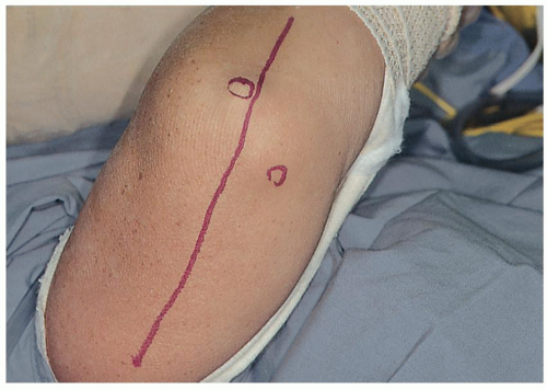 FIGURE 36A-1 A straight incision is made between the medial epicondyle and the tip of the olecranon. |
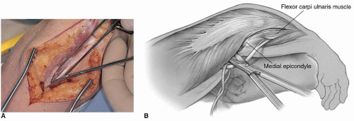 FIGURE 36A-2 A,B: The ulnar nerve is identified at the medial margins of the triceps. |
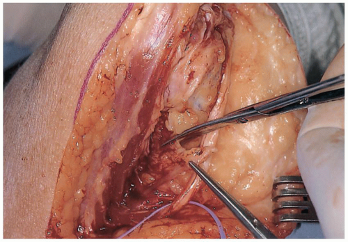 FIGURE 36A-3 Intermuscular septum is removed. A deep subcutaneous pocket is created to receive the ulnar nerve. |
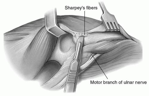 FIGURE 36A-4 The soft tissue is elevated from the subcutaneous border of the ulna and the medial margin of the triceps from the posterior aspect of the humerus. |
Note: Unless the radioulnar joint is painful or limits motion, the radial head is not resected. Leaving it serves as a source for flange bone graft at revision should that become necessary.
The tip of the olecranon is removed and the medial and lateral collateral ligaments are released from their humeral attachment (Fig. 36A-5). The distal articulation then separates from the humerus (Fig. 36A-6). The humerus is then carefully externally rotated allowing further flexion and separation of the articulation (Fig. 36A-7).
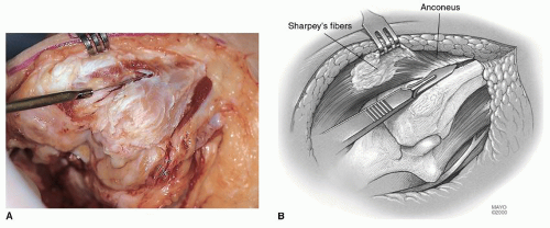 FIGURE 36A-5 A,B: The anconeus is released and maintains the continuity of the extensor mechanism. |
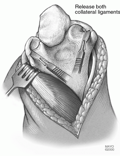 FIGURE 36A-6 Release of the medial-lateral collateral ligaments. |
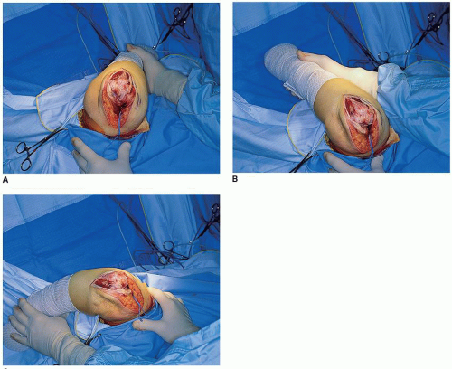 FIGURE 36A-7 A-C: External rotation of the humerus is termed “the maneuver.” Externally rotating the humerus and flexing the elbow allows ready access to the entire humerus and ulna, especially after the ligaments are released. |
Humeral Resection
The midportion of the trochlea is removed with a rongeur or saw (Fig. 36A-8) to allow the medullary canal of the humerus to be identified which is entered with a burr or rongeur through the roof of the olecranon fossa (Fig. 36A-9). The length of the medullary canal of the humerus is identified with the twist reamer/alignment guide awl (Fig. 36A-10). The medial and lateral aspect of the supracondylar columns should be identified and visualized throughout the preparation of the distal humerus so as to assure proper implant alignment and orientation. The handle of the alignment stem is removed and a cutting block attached that allows accurate removal of the articular surface of the distal humerus.
The side arm of the cutting block is attached to the radial side and rests on the capitellum in order to provide the appropriate width of cut (Fig. 36A-11). With an oscillating saw, the trochlea is removed according to the width of the cutting block, which corresponds to the appropriate size of the humeral component. Care should be taken to avoid violating either supracondylar bony column since this may cause a stress riser that can result in fracture of this structure (Fig. 36A-11B). The proximal cut usually leaves the cortical bone intact on either side of the guide. The humerus is further prepared by serial rasping in such a way as to receive the appropriate-sized humeral component (Fig. 36A-12).
This results in a final opening in the roof of the olecranon fossa smaller than that of the diameter of the medullary canal. Thus, effective plugging of the canal requires a special flexible-expansile medullary plug design or the use of cement or bone graft. The anterior capsule is released from the anterior aspect of the distal humerus and the brachialis muscle elevated with a curved 12- to 20-mm osteotome (Fig. 36A-13).
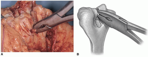 FIGURE 36A-8 A,B: A rongeur for soft bone or oscillating saw for more sclerotic bone is used to remove the midportion of the trochlea. |
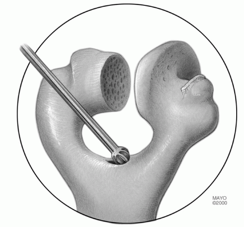 FIGURE 36A-9 The roof of the olecranon is entered with a rongeur or bur and expanded to receive the twist reamer. |
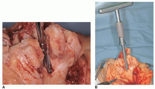 FIGURE 36A-10 The canal is entered with a twist reamer (A) that serves as an alignment guide with a removable handle (B). |
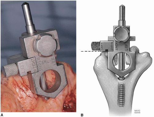 FIGURE 36A-11 A,B: The handle is removed from the alignment device and the humeral cutting jig is in place. |
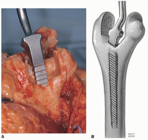 FIGURE 36A-12 A,B: The humeral canal is rasped to the appropriate size. |
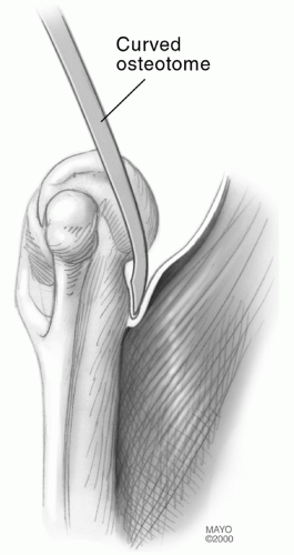 FIGURE 36A-13 The anterior capsule and brachialis muscle insertion are released from the anterior humeral cortex with a curved osteotome. |
Preparation of the Ulna
The medullary canal of the ulna is then identified by using a high-speed burr to remove the subchondral bone at the base of the coronoid (Fig. 36A-14


Related posts:

Stay updated, free articles. Join our Telegram channel
Full access? Get Clinical Tree
