Articulated External Fixators
Bernard F. Morrey
OVERVIEW
There are two principal goals simultaneously achieved with articulated external fixators:
To allow active or passive motion
To protect the articular surfaces and the collateral ligaments
DESIGN CONCEPT
RATIONALE
The scientific basis of articulated external fixators has been studied in detail in the laboratories of the Mayo Clinic and by others. Reliable identification of the axis of rotation and rigid skeletal fixation can be obtained by an articulated device that replicates the axis of rotation. Relevance of the accuracy of axis replication is not clear. Madey et al. (3) observed 3.70-fold increase in energy with as little as malalignment. Studies from our laboratory have demonstrated that while anatomic replication is of importance, the function of the fixator is altered minimally by inaccuracies less than 5 mm.
Over the last several years of particular importance is the study of Kamineni et al. (4) In this investigation, the medial and lateral collateral ligaments were released and varus/valgus stress was then imparted to the forearm. It was demonstrated that both varus and valgus stabilities of the elbow are either restored to normal or dramatically improved even with both collateral ligaments released (Fig. 12-1).
INDICATIONS
Trauma
Tenuous fixation of articular fractures
Distal humeral stems
Radial head
Coronoid
Olecranon
Protect collateral ligament reconstruction
Assure maintenance of congruency of the ulnohumeral joint
Managing the unhappy triad: fractures of coronoid, radial head, and ligament rupture
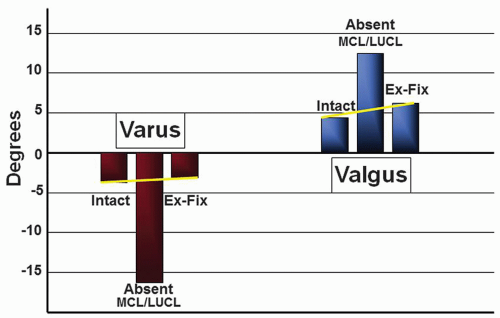 FIGURE 12-1 The half-pin configuration applied laterally provides restoration of varus and valgus stability when both collateral ligaments are deficient. (Modified from Kamineni S, Hirahara H, Neale P, et al.: Effectiveness of the lateral unilateral dynamic external fixator after elbow ligament injury. J Bone Joint Surg 89A(8): 1802-1809, 2007.) |
RECONSTRUCTION
Protect collateral ligament—protect interposition from load during healing.
Options
Several designs are currently available: (Fig. 12-2). The DJD II (Stryker, Rutherford, NJ) was designed by the author, and its application is illustrated in this chapter. It may be used in either a unilateral or a bilateral configuration. This allows a great deal of flexibility of use for a wider range of indications.
Selection Features
When determining which fixator should be used, several variables might be considered.
Simplicity of frame construction
Ease to replicate the elbow’s natural axis of rotation
Excursion of joint distraction mechanism (1 to 10 mm)
Unilateral or bilateral frame configuration options
Simple, user friendly, and safe instrumentation
Ability to avoid implants already in place
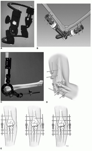 FIGURE 12-2 Several designs of articulated fixators are available with varying features (see text). A: Compass Hinge (Smith and Nephew, Mississauga, Ontario, Canada). B: Orthofix (Orthofix Inc., McKenny, Texas). C: OptiROM (EBI, Parsipenny, NY). D: DJD ll (Stryker, Kalamazoo, MI). E: Fixability is attained with half-pin application options. |
OPERATIVE TECHNIQUE
Unilateral Frame
Several reconstructive and traumatic clinical circumstances dictate the application of an articulated external fixator. At the completion of the principal procedure managing acute trauma or after a reconstruction procedure, the application of the external fixator is identical. In this chapter, the application of the DJD II is described as the author has greatest familiarity with this device and believes it to be relatively simple and affordable.*
Half-Pin Application Land Mark Identification
POSITION Regardless of the pathology being addressed, identification of the medial and lateral epicondyles is required. This may be done by direct visualization or by palpation. The flexion axis passes through tubercle at the site of the origin of the lateral collateral ligament. On the medial aspect of the distal humerus, the axis of rotation lies just anterior and inferior to the medial epicondyle (Fig. 12-3).
AXIS OF ROTATION AND REFERENCE STYLUS PLACEMENT The pointed tip of the humeral axis target guide is placed on the medial side, with the cannulated stylus guide applied to the lateral side of the joint. The reference stylus is tapped in place with a mallet through to lateral cannula of the target device (Fig. 12-4) and acts as an axis guide during frame construction. Since the axis stylus is smooth, it may be placed after ligament repair without concern of damaging the site of repair.
Note: The stylus is under development and may not be universally available.
PLACEMENT OF THE DJD II FRAME ON THE REFERENCE PIN The hollow bored hinge of the DJD II is placed over the reference pin so that its hinge is exactly in the same axis of rotation as the natural axis of rotation of the elbow. The 5-mm humeral rod of the fixator is aligned to the anterior cortex of the humerus (Fig. 12-5).
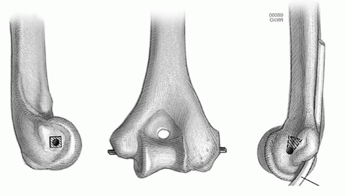 FIGURE 12-3 The landmarks on the distal humerus medial and lateral. |
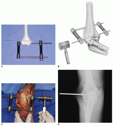 FIGURE 12-4 The pointed tip of the humeral axis guide is placed medially under direct vision at the anterior/inferior aspect of the medial epicondyle, allowing accurate orientation of the axis reference pin (A). The stylus axis pin is safely tapped into place even after the ligament has been repaired (B-D). |
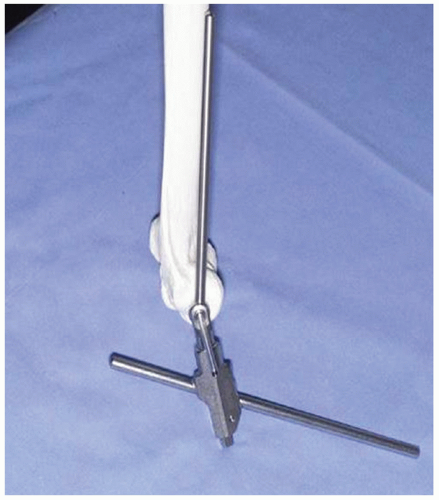 FIGURE 12-5 The fixator is placed over the reference pin, and the humeral element of the fixator is aligned with the anterior cortex of the humerus; using the pin insertion guide, a proximal half-pin is placed through the lateral and medial humeral cortices. |
Humeral Pin Insertion Note: The proximal pin is placed first, and the site of insertion is located according to the “safe zone” of pin placement as described by Kamineni et al. (5) The dimension of the epicondylar width defines a measurement to locate a safe distance proximal to the axis for placement of the proximal humeral pin. The maximum distance of the proximal humeral pin from the reference stylus should not exceed the epicondylar dimension “D” (Fig. 12-6).
PROXIMAL PIN APPLICATION The pin guide is applied to the fixator and a skin incision is made. The 4-mm (or 3 mm for small bones) cannulated trocar is inserted through the pin guide to engage the lateral humeral cortex (Fig. 12-7). The proximal humeral self-drilling/self-tapping 4 mm (or 3 mm) pin is advanced until it engages or penetrates the medial cortex. The proximal pin is fixed to the humeral rod with a pin-to-rod coupling clamp. A second 4-mm (or 3-mm) self-drilling/selftapping pin is inserted and secured in an identical fashion.
Note:


Related posts:

Stay updated, free articles. Join our Telegram channel
Full access? Get Clinical Tree
