Fig. 11.1
(a) Panoramic radiograph of impacted third molar showing increased potential for nerve injury with loss of superior cortical outline of the IAC (inferior alveolar canal) in the region of the tooth roots. (b) Panoramic radiograph of impacted third molar with radiographic predictors of nerve injury, including loss of superior cortical outline of the IAC, and darkening of the tooth roots. (c) Panoramic radiograph of left mandible fracture associated with an impacted third molar, showing mild displacement and discontinuity of the IAC. No information is provided about the status of the IAN itself
Other types of plain radiographs such as periapical (Fig. 11.2) or anteroposterior films and lateral cephalograms are not routinely used for accurate preoperative routine risk assessment for IAN injury. Superimposition and wide variations in magnification of the structures based on their location do not allow for reliable and reproducible information to be obtained with plain films. Furthermore, even if the IAN could be visualized in the third molar region, only a rough outline of tooth and root anatomy would be obtained making these images of limited if any value for nerve injury appraisal.
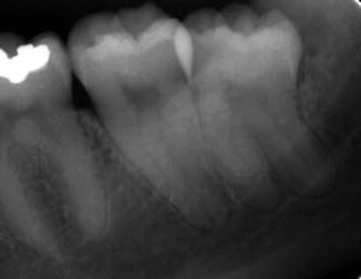

Fig. 11.2
Periapical radiograph showing proximity of third molar roots to the IAC, with root darkening
11.3.2 Computerized Tomography
The use of computerized tomography (CT) in the assessment of nerve injuries is very limited, although it has been used more recently for assessment of the inferior alveolar canal with regard to the position of the third molar. An evaluation of bone window attenuation images may indicate violation of the cortical outline of the inferior alveolar canal, either from the roots of the third molar, iatrogenic implant placement, or following facial trauma (e.g., posterior mandible fracture) (Fig. 11.3), but yields little information regarding the condition or integrity of the IAN itself or the neurovascular bundle. The use of soft tissue window CT images for the LN or IAN is compromised by very poor detail resolution that precludes its routine application in neural assessment. Furthermore, dental artifacts often pose severe limitations in obtaining accurate information regarding the position of the LN to the lingual cortex of the mandible in critical areas, even in the soft tissue window views, and despite the current use of high-resolution image acquisition.
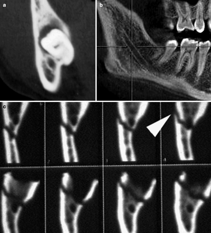
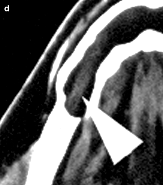


Fig. 11.3
(a) CBCT scan with coronal soft tissue window images showing the IAC displaced inferiorly and the roots of the tooth perforating the lingual plate, with the inability to discern any components of the inferior alveolar neurovascular bundle. (b) CBCT scan sagittal image with improved detail resolution of the position of the IAC. (c) CT scan images with coronal bony window images showing mandibular fracture involving the IAC (arrowhead). (d) CT scan with axial soft tissue window images in a patient with a cystic lesion of the mandible showing the inferior alveolar neurovascular bundle without significant detail (arrowhead)
In 1998, CT cone beam (CBCT) technology, previously used only in angiographic imaging, was employed in the United States as a potential imaging modality for the maxillomandibular complex. The presurgical evaluation of impacted mandibular third molar relationship to the IAN has gained popularity over conventional CT scanning and plain panoramic radiographs among oral and maxillofacial surgeons. The need for accurate imaging with the lowest possible dose of radiation (i.e., ALARA rule, as low as reasonably achievable) seems to be satisfied acceptably with this technology. CBCT provides the desirable three-dimensional representation of the anatomic location of interest, with minimal distortion compared to traditional plain films and by simpler acquisition compared to traditional CT systems. Similar to the panoramic radiograph, CBCT can be used for preoperative risk assessment in various dentoalveolar procedures such as third molar surgery or dental implants and preprosthetic surgery. A major limitation, of course, remains the inability to visualize the IAN itself (within the inferior alveolar canal), or the LN, since no accurate soft tissue information can be obtained with use of CBCT (Fig. 11.4).
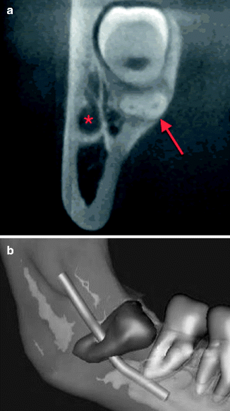

Fig. 11.4
(a) CBCT image in the mandibular third molar region showing buccal displacement of the IAC (asterisk) and thinning of the lingual plate near the third molar roots (arrow). Neither the IAN nor LN is visible on these images. (b) Three-dimensional CBCT reconstruction showing position the course of the inferior alveolar canal between the impacted third molar roots. This is merely a reconstruction of the inferior alveolar canal without any information about the IAN itself
11.3.3 High-Resolution Magnetic Resonance Imaging (HR-MRI)
Magnetic resonance imaging (MRI) is the method of choice for radiographic visualization of all cranial nerves (CN), and each nerve segment can be seen and examined in detail with specific MRI sequences. Due to the complexity of the course f the CNs and surrounding anatomic structures, detailed examination of the CNs is made possible only with careful planning and selection of the specific MRI technique. The imaging plane, coil selection, slice selection, in-plane resolution, and use of special techniques can be tailored based upon the individual CN, and the segment of interest so that the highest possible image quality may be obtained. The trigeminal nuclei (intra-axial), cisternal portion (preganglionic), and Meckel’s cave (intradural) segments contain both the motor and sensory components of the trigeminal nerve and can be visualized with high-resolution T1- or T2-weighted MRI images. At the anterior aspect of the Gasserian ganglion, the sensory root divides into the ophthalmic (V1), maxillary (V2), and mandibular (V3) divisions and each may be followed and examined separately based upon their known course peripherally. The course of the LN and IAN branches of the mandibular division, after exiting from foramen ovale, can be followed with high-resolution, contrast-enhanced, T1-weighted (T1W), or T1W three-dimensional, fast-filed echo (T1W 3D FFE) sequences in the axial, coronal, and sagittal, or parasagittal, planes. Although detailed information can be obtained with the use of MRI, routine presurgical evaluation of the route and integrity of the LN and IAN is not standard practice. Rather the MRI is employed as the preferred imaging modality for examination of the status of the CNs most commonly in the presence of a disease process or following brain or nerve injury.
Miloro et al. have used high-resolution MRI (HR-MRI) in an attempt to document the in situ position of the LN in the third molar region directly, without surgical manipulation or tissue distortion artifact as in the studies by Kisselbach and Pogrel. Ten patients (20 sides) without prior dental surgery were imaged using an HR-MRI sequence (PETRA-phase encode time reduction acquisition) that enabled direct visualization of the LN (Fig. 11.5). This study documented that the lingual nerve position, while variable, was indeed vulnerable during third molar surgery, and the LN was found to be superior to the lingual crest in 10 % of cases, and in direct contact with the lingual plate in 25 % of cases. Kress and colleagues have been able to image the IAN using T2-weighted MRI imaging to visualize the IAN in the in situ position as well as in cases of mandibular fractures (Fig. 11.6); yet there is still lack of detailed resolution of the fascicular anatomy of the IAN itself.
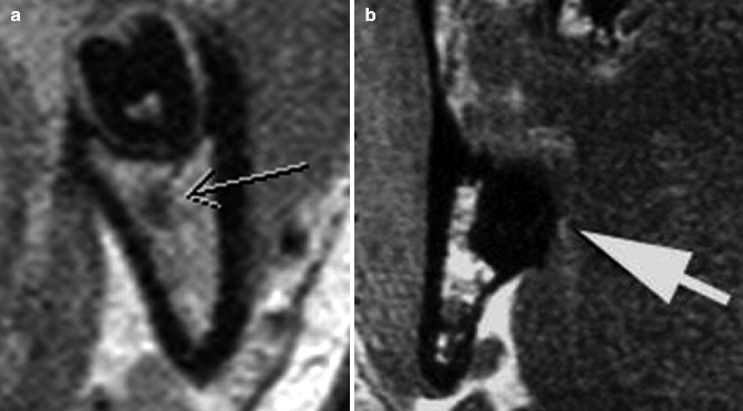
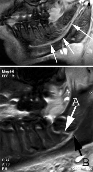

Fig. 11.5
(a) High-resolution MRI (HR-MRI) image in the third molar region showing minimal detail of the inferior alveolar neurovascular bundle (arrow). (b) High-resolution MRI (HR-MRI) image in the third molar region. Arrow indicates lingual nerve in direct contact with the lingual cortical plate (arrow)

Fig. 11.6
(a) Sagittal mandibular MRI image of a normal inferior alveolar nerve (arrows) (Adapted from Kress et al. [17], p. 1636). (b) Sagittal mandibular MRI image of a mandible fracture associated with the mesial aspect of the impacted third molar (A), showing continuity of the inferior alveolar nerve (B) but lack of detailed fascicular anatomy (Adapted from Kress et al. [17], p. 1636)
11.3.4 Ultrasonography
Several reports have described the use of ultrasonography (US) and high-resolution ultrasound technology primarily for the assessment of peripheral nerve lesions. This real-time advanced technology, with recently available high-resolution probes, can offer compound imaging without radiation and in a relatively inexpensive manner. Although US has not been employed or investigated as a potential preoperative risk assessment tool for the trigeminal nerve, it has been demonstrated to be valuable in identification and safe advancement of the needle in brachial plexus and sciatic nerve blocks. It would be reasonable though to anticipate limitations with the use of US in examination of the IAN in the third molar region due to the presence of bone and teeth that might affect the echogenic signal. Visualization and documentation of the course and integrity of the LN on the other hand should be relatively easy with US, requiring only minimal training and familiarity of the operator with the regional oral anatomy (Fig. 11.7).
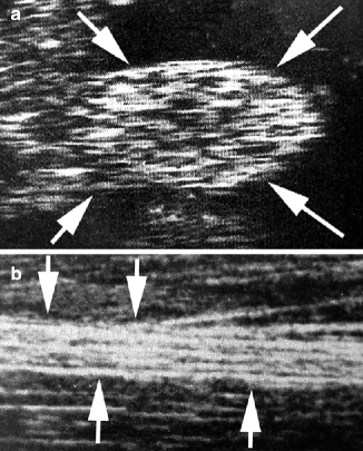

Fig. 11.7
(a) High-resolution ultrasound image of sciatic nerve in cross section. Note ability to visualize fascicular pattern (arrows). (b) High-resolution ultrasound image of sciatic nerve in longitudinal section (arrows) (Adapted from Graif et al. [10])
11.4 Post-Injury Radiographic Assessment of the IAN and LN
The majority of current interest is in documenting the post-injury condition of the nerve by objective means, since the information gathered by clinical and radiologic examination could be useful in staging the degree of neural injury, determining the prognosis for recovery, and planning microneurosurgical intervention. With increased image resolution, the precise degree of architectural disruption of the nerve could be visualized, and surgical intervention could be planned accordingly. Additionally, this information could be used to document the exact location of the injury prior to surgical exploration for repair. For example, this documentation could help to avoid surgical nerve exploration in the third molar region if the injury occurred in the pterygomandibular space as a result of a mandibular block injection injury. The information may also be used to determine the size and extent of the neuromatous segment and the possible need for a nerve graft. Finally, radiologic techniques could be used to objectively monitor neurosensory progression, in conjunction with clinical examination, either after nerve injury or in the post-repair phases of neural recovery.
11.4.1 Panoramic Radiography
The post-surgery assessment of the nerve-injured patient usually includes a panoramic radiograph that may demonstrate a variety of clinically significant findings. The presence of a foreign body in the region of one or both nerves must be ruled out; and these may include metallic foreign bodies from rotary instruments or amalgam particles from neighboring teeth, as well as retained tooth or root fragments following third molar surgery. Also, the presence of iatrogenic surgical disturbances of the nerves may be indicated by evidence of bone removal in proximity to the inferior alveolar neurovascular bundle or the lingual nerve (Fig. 11.8). A panoramic radiograph, or any other plain film, is rarely used though to monitor progression following nerve injury or repair.
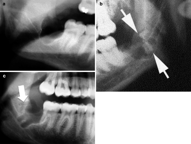

Fig. 11.8
(a) Panoramic radiograph post-extraction, showing evidence the presence of radiographic predictors of potential IAN injury. (b) Panoramic radiograph showing retained root tips following third molar extraction (arrows) that may impede neural regeneration. (c) Panoramic radiograph showing evidence of bone removal distal to the third molar socket (arrow) in a patient with a left lingual nerve injury
11.4.2 Computerized Tomography
Postoperative investigation of the surgical site for examination of the integrity of the IAN canal or presence of foreign material, such as tooth or root fragments within the canal, could be more reliably performed with CT or CBCT imaging rather than using traditional panoramic imaging. Direct investigation of the integrity of the LN cannot be reliably examined with either modality due to the fact that there is not bony conduit surrounding the nerve. Disruption of the lingual cortex of the mandible at the third molar region, which may be noted on a postoperative panoramic radiograph and which may imply iatrogenic injury in the region, can be reviewed in more detail with CT or CBCT (Fig. 11.3). Direct comparisons of pre- and postoperative images can be made and add to the information gathered from the clinical examination, and potentially assist in the decision-making process for surgical or nonsurgical management.
Stay updated, free articles. Join our Telegram channel

Full access? Get Clinical Tree


