CHAPTER 29 Glenoid Component
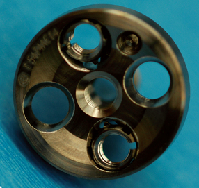
Unlike cases of unconstrained shoulder arthroplasty, in which placement of a glenoid component is optional, the glenoid component must be placed during reverse shoulder arthroplasty. As in unconstrained arthroplasty, adequate glenoid exposure is paramount in placement of the glenoid component and is covered in Chapter 27. Many different implant companies are now manufacturing reverse-design shoulder prostheses. The glenoid components of the various brands generally consist of an uncemented metal base plate and a modular metallic glenosphere. The number and orientation of fixation screws used for the base plate and the design of the base plate (flat back versus convex back) vary among manufacturers. The specific implant with the longest and most successful follow-up is the Grammont-designed Delta (DePuy, France). Our preference is to use an implant that does not differ appreciably from this clinically tested design. The Grammont-designed Delta base plate consists of a flat back with a central peg and is fixated with four peripheral cortical screws. The glenosphere is placed over the base plate to allow a medialized center of rotation. The technique described in this chapter is applicable to this type of reverse glenoid component.
GLENOID PREPARATION AND COMPONENT IMPLANTATION
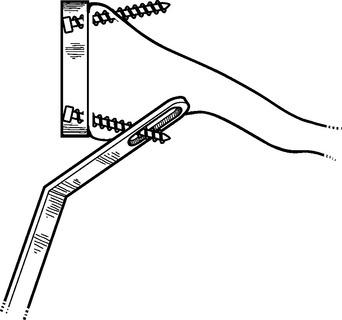
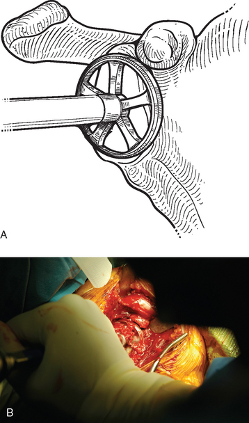
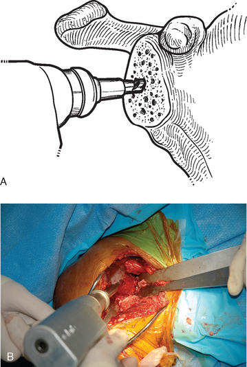
After humeral preparation is complete (see Chapter 28), the proximal humerus is retracted posteriorly with a Trillat glenohumeral retractor or a large glenoid rim retractor (see Chapter 3). We avoid using a Fukuda glenohumeral retractor during implantation of a reverse prosthesis because the base plate fixation screws may incarcerate the retractor (Fig. 29-1). After the glenoid is exposed by retracting the proximal humerus posteriorly, a drill hole is made with the inferior referencing guide provided. The guide is placed at the inferior border of the glenoid to align the inferior aspect of the glenosphere with the inferior aspect of the glenoid (Fig. 29-2). Placing the glenosphere in this position will help minimize the incidence of notching of the axillary border of the scapula as a result of the mechanical contact that occurs after implantation of the reverse prosthesis.
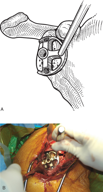
Figure 29-2 A and Placement of the inferior referencing guide for drilling the initial hole in the glenoid face.
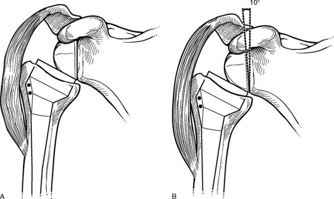
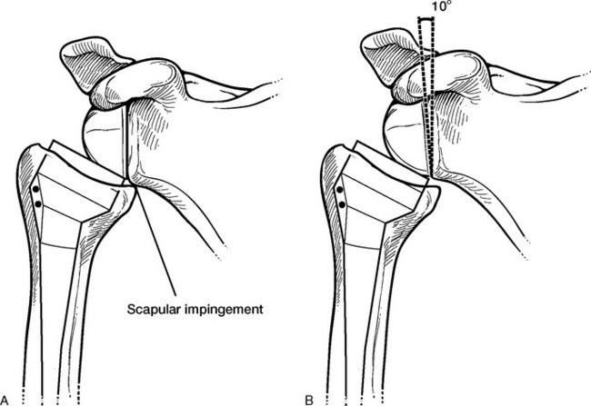
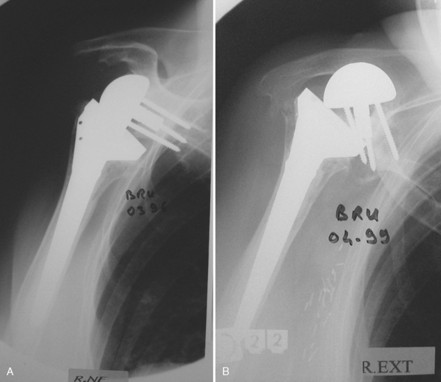
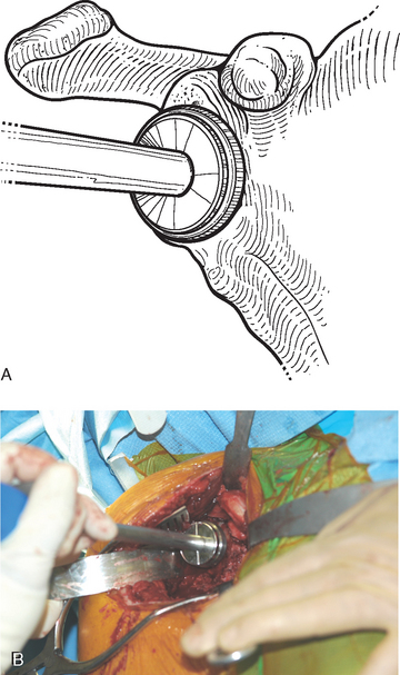
Reaming is performed while placing slight inferior pressure on the reamer to introduce approximately 10 degrees of inferior tilt to the surface of the glenoid. This inferior tilt serves three purposes: first, it increases stability of the prosthesis by maximizing deltoid tension through distalization of the humerus (Fig. 29-3); second, it reduces the incidence of scapular notching (Fig. 29-4); and third, it helps avoid inadvertently placing the glenoid component in a superiorly oriented position, which can lead to early glenoid failure (Fig. 29-5). Reaming is performed only to remove any remaining cartilage and flatten the glenoid surface. It is not necessary to ream to cancellous bone, and such reaming should be avoided. Additionally, many patients undergoing implantation of a reverse prosthesis have osteopenic bone that is susceptible to fracture during glenoid preparation. To help avoid fracture, the reamer is always started before contacting the bone and then gradually and gently advanced to engage the bone and ream it to a flat surface (Fig. 29-6). Once reaming is complete, the cortical aperture of the glenoid hole is opened to a slightly larger diameter (7.6 mm) to accommodate the central peg of the glenoid base plate (Fig. 29-7). In patients with moderate to severe osteopenia, this step may be omitted.
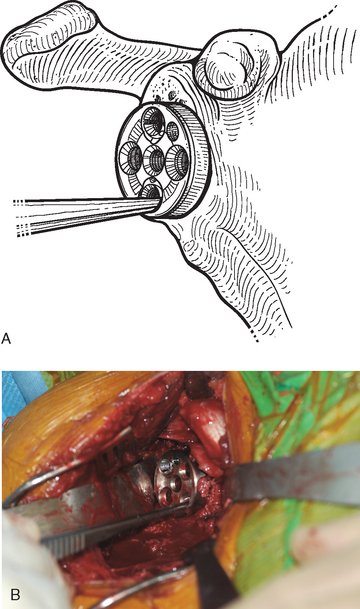
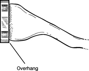
The glenoid base plate is oriented and introduced with the insertion handle (Fig. 29-8). A mallet is used to impact the base plate until it is flush with the glenoid bone circumferentially. The insertion handle is disengaged from the base plate, and the base plate is checked to ensure that it has been completely seated by inserting the tips of vascular forceps into each hole (Fig. 29-9). If any concern exists over incomplete seating of the base plate, a large smooth tamp may be used to further impact the base plate. Additionally, the peripheral inferior rim of the base plate should be confirmed to be in contact with underlying glenoid. If the implant is not seated inferiorly, early glenoid loosening can occur. Occasionally, the base plate will be larger in anteroposterior diameter than the native glenoid, such as with bone loss or in a small patient (Fig. 29-10). This is not generally a problem as long as bone is visible in the anterior and posterior base plate holes. If the bone loss is severe, bone graft reconstruction of the glenoid may be necessary (see the following section of this chapter).
The next step involves screw insertion to complete fixation of the base plate. Fixation of the glenoid base plate in our chosen prosthetic system involves the use of two different types of screws. The inferior and superior screws lock into a mobile variable-angle washer captured in the base plate to create a fixed-angle device once the screw is tightened. The anterior and posterior screws are placed through a standard hole within the base plate that does not contain a locking mechanism (Fig. 29-11). The anterior and posterior screws can be placed at variable angles and allow compression of the base plate against the glenoid bone, whereas the inferior and superior screws “set” the distance between the implant and glenoid bone as soon as the threaded head engages the locking washer within the base plate (Fig. 29-12). Because of these special considerations, the screws are inserted and tightened in a specific order. The inferior screw is placed first to ensure maintenance of contact of the inferior aspect of the base plate with the underlying osseous glenoid. A drill guide is placed in the inferior hole of the base plate. A drill (3.0-mm bit) is used through the guide to create a bicortical hole (Fig. 29-13). The direction of the drill should be chosen to maximize screw length so that the strongest fixation possible is provided. Because of the inferior position of the base plate, if the drill is directed too inferiorly, it may exit the glenoid bone prematurely and result in poor fixation (Fig. 29-14). If the drill is passed perpendicular to the base plate, screw length may be shorter than desired (Fig. 29-15). We have found that directing the drill halfway between the perpendicular and the maximal inferior direction allowed by the mechanical constraints of the base plate permits consistent placement of a sufficiently long screw (Fig. 29-16).
Stay updated, free articles. Join our Telegram channel

Full access? Get Clinical Tree


