Fusion – Minimally Invasive Techniques

CHAPTER 132 Fusion – Minimally Invasive Techniques


INTRODUCTION


Minimally invasive spinal surgery strives to achieve the goals of surgery while minimizing the iatrogenic injury incurred during the exposure process. The development of the microscope, laser technology, endoscopy, video and image guidance systems provided the foundation for minimally invasive spinal surgery. Minimally invasive treatments have been made in all areas of the spinal axis since the twentieth century. Lumbar disc disease has been treated by using chemonucleolysis, percutaneous discectomy, laser discectomy, intradiscal thermoablation, and minimally invasive microdiscectomy techniques. The use of thoracoscopy initially for thoracic discs and tumor biopsies has expanded to include deformity correction, sympathectomies, resection of paraspinal tumors, and vertebrectomy with reconstruction and instrumentation. Laparoscopic techniques as used for appendectomies or cholecystectomies by general surgeons have evolved into use by spinal surgeons for anterior lumbar discectomy and fusion. Image-guided systems have been adapted to facilitate pedicle screw placement with increased accuracy. Over the past decade, minimally invasive treatment of cervical spinal disorders has become feasible using similar technologies as developed for the thoracic and lumbar spine. Endoscopically assisted transoral surgery, cervical decompression, and instrumentation all represent the continual evolution of minimally invasive spinal surgery. Further improvement in optics and imaging resources, development of new biological agents such as recombinant human bone morphogenetic protein (rhBMP), and the introduction of innovative instrumentation systems designed for minimally invasive procedures have expanded significantly over the past decade to make minimally invasive fusion possible. The authors will discuss different techniques of minimally invasive fusion as it pertains to each segment of the spinal column.


LUMBAR SPINE


Minimally invasive PLIF and TLIF


The concept of lumbar interbody fusion as initially described by Cloward in 1951 offers several advantages over the traditional posterolateral arthrodesis including a rich blood supply from the cancellous fusion bed, a load-bearing force occurring through the fusion bed, the ability to distract the disc space and neuroforamina, and the ability to restore segmental lordosis. Traditional open posterior lumbar interbody fusion (PLIF) procedures have been reported to yield successful outcomes in approximately 80% of patients with fusion rates near 90%. Since 2000, minimally invasive PLIF (MI-PLIF) procedures have been utilized to reduce iatrogenic injury incurred during the exposure process of the open procedure. Long-term follow-up data are lacking, but retrospective reviews of MI-PLIF performed with the microscope, premachined bone graft or cages, virtual fluoroscope, and percutaneous pedicle screw system at greater than 1-year follow-up were reported to yield clinical improvement comparable to the open procedure.1,2


Surgical technique


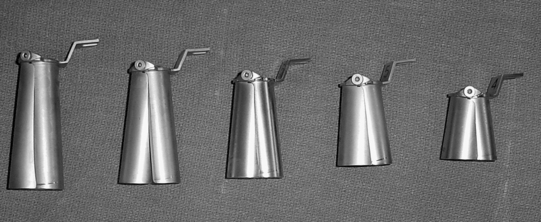
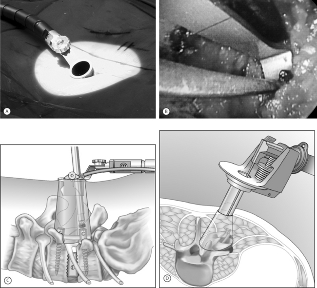
An expandable tubular retractor (X-Tube, Medtronic Sofamor Danek, Memphis, TN) (Fig. 132.1) can be used to accomplish a minimally invasive TLIF. The tube is inserted at a diameter of 26 mm and is expanded in situ to a final working diameter of 44 mm (which can span from pedicle to pedicle). Use of an endoscope or the operating microscope is possible through this tubular retractor (Fig. 132.2A). The basic surgical set is essentially the same as a standard laminectomy/fusion set. It is important to have a high-speed telescoping drill (Midas Rex, Ft. Worth, TX) available as an aid for removing bone. Instruments should be bayoneted so that visualization of the operative field is not occluded down the barrel of the tubular retractor. The tools for disc space preparation prior to graft placement consist of distractors (7–14 mm), rotating cutters, endplate scrapers, and chisel. Many options exist for interbody graft material and can include bone or cages (with autologous bone or BMP-2 [Medtronic Sofamor Danek, Memphis, TN]).


The operating room is arranged such that the operating table is in the center of the room, anesthesia at the head and fluoroscopy monitor at the foot. The C-arm base is placed on the side opposite of the TLIF as is the video monitor. Equipment tables are kept behind the surgeon on the operative side and a Mayo stand is situated over the feet to pass instruments in active use. The patient is positioned prone on a radiolucent Wilson frame over a Jackson table.


Localization and exposure


The region of pathology is localized with aid of fluoroscopy and a Steinman pin. Once marked, a stab incision is made 3 cm from midline, and the Steinman pin is inserted until it rests on bone. Ideally, the pin should be on the facet complex of the affected level and the skin incision extended to a length of 3 cm. Sequential tubular dilators are passed over one another and fluoroscopy is used to confirm adequate insertion. The appropriate-length working channel (X-tube) is introduced over all the dilators, brought into line with disc space in a medial orientation and secured to the operating table with a flexible arm clamp. The X-tube working channel is opened to its full capacity, which should span the distance from pedicle to pedicle at the level of interest. Muscle and soft tissue are cleared from the lamina and facet with monopolar cautery. Next, the working channel is angled laterally, and the transverse processes are exposed. The tubular retractor is turned medially to begin the laminotomy and facetectomy. The decompression should extend from pedicle to pedicle in a rostral–caudal direction. Laterally, a total facetectomy is done to provide adequate space for graft placement and to minimize root retraction. Next, the ligamentum flavum is removed. Epidural veins are coagulated with bipolar cautery and divided if necessary. The lateral edge of the dura, the nerve root, and the disc space should be clearly visualized.


The anulus is cut and disc material is removed with pituitary rongeurs. A down-angled curette is helpful to ensure that subligamentous disc fragments and the contralateral disc are properly removed. The disc space is sequentially dilated until disc space height is similar to adjacent levels. The maximum insertable dilator translates into the width of the interbody graft used. Next, the rotating cutter is introduced parallel with the disc space and rotated to start preparing the vertebral body endplates. The endplates are scraped, and debris is removed with a pituitary rongeur. A disc space chisel can be used to better prepare the endplates. A graft of surgeon’s preference can now be placed (see Fig. 132.2B). Medial angulation of the tube will allow for midline graft placement. One should also pack autologous laminofacet bone removed during the decompression, anteriorly into the disc space prior to graft placement. The X-tube can also be repositioned laterally if a unilateral intertransverse fusion is desired.


Instrumentation with sextant


In conjunction with the use of the X-tube, pedicle screw placement can be performed percutaneously with use of the sextant instrumentation set (Medtronic Sofamor Danek, Memphis, TN). For use of a single fluoroscopy machine, the ‘bull’s eye’ technique for percutaneous pedicle screw placement is adequate and more straightforward. On the other hand, if triangulation of the pedicle screws is desired, biplanar fluoroscopy is used for placement in a manner similar to a vertebroplasty procedure. Alternatively, image-guided systems can be used depending on surgeon’s comfort and preference. For the ‘bull’s eye’ pedicle screw placement, the C-arm is rotated 90° for a true anteroposterior (AP) view parallel with the disc space. The bone biopsy needle is localized over the pedicle and passed through the soft tissue onto the pedicle so that the needle will appear as a single spot (‘bull’s eye’) in this orientation. The needle is taped into the pedicle with a mallet and position is confirmed by fluoroscopy. Then, with the needle held firmly in the correct orientation, the stylet is removed and a K-wire is drilled approximately 1 cm into the pedicle. The bone needle is removed and fluoroscopy is used to confirm that the K-wire is in the center of the pedicle. The process is repeated for the contralateral pedicle and then for both pedicles at the adjacent affected level. The C-arm is brought to the lateral position for advancement of the K-wires to approximately two-thirds the length of the vertebral body parallel with the endplate. Soft tissue over the K-wires is dilated, the pedicles are taped, and cannulated screws are inserted. Attention is paid to the K-wire as accidental removal or advancement would be undesirable. The sextant device is attached to the screw extenders and pushed through the soft tissue to create a tract for the rod. The rod size is calculated by placing templates on the sextant at this point. The tip of the sextant is replaced with the rod, which is pushed through the soft tissue and both screw heads. The C-arm is brought to the AP orientation to confirm the rod has passed through both screw heads before tightening. The screws are then compressed, tightened, and broken off with a torque wrench. The sextant is disconnected from the rod and removed. The process is repeated on the opposite side.


In essence, if percutaneous pedicle screw placement is not desired, surgical instruments and fixation can all be applied directly through the retractor port (see Fig. 132.2C). Examples of commercial access systems in addition to the METRx Minimal Access System (Medtronic Sofamor Danek; Memphis, TN), include the Access Port (Spinal Concepts; Austin, TX), the Nuvasive system (Nuvasive; San Diego, CA) and the ATAVI System (Endius; Plainville, MA). The central mechanism of each of these systems is fundamentally that of tubular dilation and a cylindrical working portal. Like the METRx Xpand system, the ATAVI Flexposure cannula (Endius) (see Fig. 132.2D) can expand its ultimate working diameter up to 40–60 mm for direct pedicle screw placement.


Laparoscopic anterior lumbar interbody fusion


Prior to the 1980s, laparoscopic procedures were mainly used in the field of gynecology and urology. The transition into general surgery began in the 1980s when the first laparoscopic appendectomy was performed in Germany. In 1987, the first human laparoscopic cholecystectomy was performed in France.3 The widespread acceptance of this minimally invasive approach can best be appreciated by noting the fact that within only 3 years after its introduction, more than 90% of all cholecystectomies were being performed laparoscopically. The significant advantages of transperitoneal laparoscopic surgical treatment include marked reductions in postoperative pain, early hospital discharges, and reduced incidences of postoperative ileus.


Anterior lumbar interbody fusion (ALIF) was initially described by Burns in 1933 for the treatment of spondylolisthesis.4 In 1995, Mathews et al.5 and Zucherman et al.6 described the technique in detail and published preliminary outcome data for laparoscopic anterior lumbar fusion. In 2000, Regan et al.7 published a prospective comparative study of open versus laparoscopic anterior lumbar fusion. They demonstrated that the laparoscopy group had a shorter hospital stay and reduced blood loss but had increased operative time. Operative time improved in the laparoscopy group as surgeons’ experience increased. Operative complications were comparable in both groups, with an occurrence of 4.2% in the open approach and 4.9% in the laparoscopic approach. Overall, the device-related reoperation rate was higher in the laparoscopy group (4.7% versus 2.3%). Conversion to open procedure in the laparoscopy group was 10%.


A more recent study did not favor the video-assisted techniques and laparoscopic approach. Escobar et al.8 published a comparative analysis focusing on the complications of three techniques (a ‘minilaparotomy’ open extraperitoneal approach through a small midline incision, a transperitoneal video-assisted insufflation technique, and a video-assisted gasless) for anterior lumbar interbody fusion in 135 patients. The study revealed the highest incidence of complications in video-assisted techniques and the laparoscopic approach. Complications are primarily related to surgical exposure of the anterior spine, which can include damage to important vascular structures, the sympathetic plexus, or the abdominal viscera.


The main disadvantage of the laparoscopic approach is the steep initial learning curve of the surgical team. Additionally, the anterior approach to cage placement is limited in being able to directly decompress the spinal canal. However, with care in patient selection, a stand-alone interbody cage fusion has been successfully demonstrated. In order to evolve to the laparoscopic placement technique of interbody cages, the access surgeon and spine surgeon should work as a team using the open approach but practice placing the particular instrumentation system they plan to use laparoscopically. Lastly, in terms of initial case selection, begin with nondeformity L5–S1 cases, as this represents the ideal case for ALIF (both open and laparoscopic).


Exposure


For L4–5 and L5–S1 the standard portal placement includes a periumbilical laparoscopic portal, a 5 mm right and left-lower abdominal quadrant dissection/retraction portals, and a suprapubic working portal. The initial portals placed include the camera and right-left lower quadrant sites. Using these portals, the dissection is performed and the desired level exposed. Once the level is verified, the suprapubic working portal is then created. This portal should allow a co-linear approach to the disc space, representing the orientation of the interbody cage within the disc space at final placement.


The autonomic plexus rests in the retroperitoneal fat layer. The posterior retroperitoneum should be opened with laparoscopic scissors rather than with cautery so that the risk of retrograde ejaculation is minimized. Incise the posterior peritoneum to the right of the midline. Middle sacral vessels can be ligated and divided for both L4–5 and L5–S1 procedures. The iliolumbar vessel is ligated and divided mainly for L4–5 procedures. The entire width of the disc space should be exposed as much as possible.


Depending on the specific cage system being used, the sequence of cage placement may vary. However, there are several aspects that are not system dependent. Throughout the procedure, the surgeon must verify the midline and the lateral margins of the entry sites for the cages. This will help ensure correct cage placement. Debris should be cleared following each step with pituitary rongeurs so that the anatomy is clearly visualized. Fluoroscopy will confirm the depth of rongeur insertion. The medial edge of the working cannula should approximate the midline disc mark. If a gap exists, the cannula has worked itself laterally. If the midline mark is covered by the cannula, the cages may impinge on one another. Carefully verify appropriate endplate preparation and engagement of the cages with the endplate using fluoroscopy so that placement of undersized cages can be avoided. Proceed with each step only after verifying adequacy of the laparoscopic exposure and retraction. Harvest iliac cancellous bone graft if a rhBMP-2 product such as InFuse (Medtronic Sofamor Danek, Memphis, TN) is not utilized.

Stay updated, free articles. Join our Telegram channel

Sep 8, 2016 | Posted by in PHYSICAL MEDICINE & REHABILITATION | Comments Off on Fusion – Minimally Invasive Techniques

Full access? Get Clinical Tree

Get Clinical Tree app for offline access