Fig. 8.1
Table 8.1
Typical range of motion at the human ankle
Type of motion | Maximum allowable motion | Mean | Standard deviation |
|---|---|---|---|
Range | |||
Dorsiflexion | 20.3°–29.8° | 24.68° | 3.25° |
Plantarflexion | 37.6°–45.75° | 40.92° | 4.32° |
Inversion | 14.5°–22° | 16.29° | 3.88° |
Eversion | 10°–17° | 15.87° | 4.45° |
Internal rotation | 22°–36° | 29.83° | 7.56° |
External rotation | 15.4°–25.9° | 22.03° | 5.99° |
For the purpose of this section, the quantification of different rotations of the foot is made through the use of Euler angles. The XYZ Euler angle convention had been adopted whereby the orientation of the foot is described by a rotation about an x-axis, followed by a rotation about the resulting y-axis and then finally a rotation about the resulting z-axis. The angular displacements about these axes are referred to as the X, Y and Z Euler angles, respectively. The arrangement of the axes (see Fig. 8.1a) was selected in such a way that in the absence of rotations about other axes, the plantar/dorsiflexion movement is described by the X Euler angle; the inversion/eversion movement is described by the Y Euler angle, and the abduction/adduction movement is described using the Z Euler angle.
It can be seen that the extent of motion available in different directions are quite different and that the overall ankle range of motion is rather small. It should be noted that since the robot should be able to cater for both the left and right legs, the different motion limits in the inversion–eversion and internal–external rotation directions will be inverted in the robot coordinate frame when a foot from the different side of the body is placed on the robot. The limits of the required robot rotational workspace on the frontal and transverse planes are therefore symmetric.
Another quantity that has a significant influence on the design of the ankle rehabilitation robot is the level of moment that the ankle–foot structure is expected to experience during rehabilitation. In terms of maximum moment required at the plantar/dorsiflexion motion, results from an in vivo study in [3] have found that a maximum range of 71.7 Nm is required to move the foot of the subject passively from maximum plantarflexion to maximum dorsiflexion. The same study also evaluated the torques produced by maximum voluntary contraction of the subjects, and the corresponding values for dorsiflexion and plantarflexion are 54.4 and 126.0 Nm, respectively. Similar results in terms of passive ankle moments were also observed in an in vitro study by Parenteau et al. [4] which gives a maximum dorsiflexion moment as −44 Nm and a maximum plantarflexion moment of about 37 Nm. Maximum joint torque in the inversion–eversion directions is also available from [4], where values of 33 Nm in inversion and 44 Nm in eversion were reported. Unfortunately, maximum torque for internal/external rotation is not available from the above studies. The robot used in this research was therefore designed by assuming that the maximum internal/external rotation moments are similar in magnitude to the inversion/eversion moments. In summary, the moment requirements of the ankle rehabilitation robot are set at 100 Nm for moments about the X Euler angle axis, and 40 Nm for the remaining two Euler angle axes.
Parallel mechanisms have a kinematic structure whereby the end effector is connected to a fixed base through multiple actuated links. Due to this arrangement, parallel robots have several advantages over their serial counterparts. One of these advantages is higher positioning accuracy since errors in the actuated joints no longer accumulate as in the case of serial robots. Furthermore, since the end effector is supported by multiple actuators, the load capacity of the mechanism can also be increased. As actuators of a parallel robot is located at its base rather than on its moving links, the total load moved by the manipulator is also reduced. As a result, parallel mechanisms can be used to achieve higher bandwidth in motion.
Due to its many advantages and the relatively large loads experienced at the ankle and foot, parallel mechanisms are excellent candidates for ankle rehabilitation devices. In fact, the human lower leg and foot can itself be viewed as a parallel mechanism with the foot being the end effector and the muscles spanning across the ankle being the actuating links. From the above discussion, it can be seen that there is sufficient motivation for the use of a parallel robot in this research. The major shortcomings of parallel mechanisms, however, come in the form of a reduced workspace and increased kinematic singularities [5, 6]. Fortunately, as the range of motion of the human ankle is rather limited, the smaller workspace of parallel manipulators may still be adequate provided that suitable kinematic parameters are selected for the mechanism. Singularities on the other hand pose a much greater concern and must be considered in the design of the manipulator. This research had therefore placed special attention on the workspace and singularity analyses during development of the ankle rehabilitation platform.
Existing ankle rehabilitation devices can be broadly classified as platform based or exoskeleton based and many have a parallel kinematic structure. The platform-based devices are mainly used in the rehabilitation of sprained ankle, and the typical set-up requires only the foot of the user to be secured onto the robot end effector. Exoskeleton-based devices on the other hand allow the user to don the robot and is generally used for gait rehabilitation. In this case, the base- and end-effector robot are attached to different limb segments across the ankle.
In many platform-based devices, the robot end effector is often constrained about a centre of rotation which is usually not coincident with the actual ankle centre. As a result of this, the shank of the user is unlikely to remain stationary during the operation of the device, and the rotational motion at the end effector in such platforms will not necessarily be identical to the relative rotations between the shank and the foot. Additionally, these designs also exert poorer control over the foot configuration and ankle moment since the ankle joint is not completely isolated from the remaining joints on the lower limb. For more advanced control strategies which adapt the robot behaviour with respect to the foot configuration, the above shortcoming can also lead to incorrect selection of controller gains. The above problem is avoided in some of the exoskeleton-based designs, where the human lower limb is utilised as part of the robot kinematic constraints and the shank is secured in place during operation. The downside to this, however, is that the robot kinematics is not fully known since the robot is underactuated prior to it being fitted onto the user. Consequently, the control of such robots can be more challenging than the fully constrained platform-based manipulators. Given its ability to provide more accurate estimates of ankle–foot configuration, this research has taken the latter approach and incorporated it into the design of a platform-based ankle rehabilitation robot.
The mobility or number of degree of freedom available in a spatial mechanism is given by the Grubler’s mobility formula shown in (8.1) [6], where  is the mobility of the mechanism,
  is the number of rigid links present in the mechanism (including the fixed base),
  is the total number of active and passive joints and
  is the degree of freedom for the
  th joint.

 is the mobility of the mechanism,
  is the number of rigid links present in the mechanism (including the fixed base),
  is the total number of active and passive joints and
  is the degree of freedom for the
  th joint.
(8.1)
In the set-up, the foot of the user is attached to the end effector and the shank is attached to the base of the mechanism. In the absence of any actuating links, the only kinematic constraint between the base and the end effector will be the human ankle joint. In this scenario,  = 2 and
  = 1. Consequently, the mobility of this mechanism,
  , is identical to that of the natural ankle joint. Clearly, actuated links must be included in the mechanism to allow control of the rehabilitation device; however, it should be noted that the mobility after the addition of actuated links must be identical to
  if the natural motion of the foot is to be preserved.
 = 2 and
  = 1. Consequently, the mobility of this mechanism,
  , is identical to that of the natural ankle joint. Clearly, actuated links must be included in the mechanism to allow control of the rehabilitation device; however, it should be noted that the mobility after the addition of actuated links must be identical to
  if the natural motion of the foot is to be preserved.
Since the actuated link must be connected to both the base and end effector for the formation of a parallel mechanism, the number of rigid body segments introduced by each actuated link must be one less than the number of joints added to the system (i.e.  ). According to (8.1), it can be seen that the mobility of the mechanism will decrease upon the addition of actuated links if the total degree of freedom of the joints on each actuated link is less than six. Based on this observation, the kinematic structure of the actuated links was chosen to be UPS to maintain the mechanism mobility at that of the human ankle. In the above notation, U is used to represent a universal joint, P for a prismatic joint and S for a spherical joint. The line beneath P is used to indicate that the prismatic joint is being actuated. The joints in a UPS link structure therefore has six degree of freedom in total, just enough to prevent any reduction in the mobility of the mechanism. Using this link structure, the number of actuated links also dictates the number of actuated degree of freedom in the system.
 ). According to (8.1), it can be seen that the mobility of the mechanism will decrease upon the addition of actuated links if the total degree of freedom of the joints on each actuated link is less than six. Based on this observation, the kinematic structure of the actuated links was chosen to be UPS to maintain the mechanism mobility at that of the human ankle. In the above notation, U is used to represent a universal joint, P for a prismatic joint and S for a spherical joint. The line beneath P is used to indicate that the prismatic joint is being actuated. The joints in a UPS link structure therefore has six degree of freedom in total, just enough to prevent any reduction in the mobility of the mechanism. Using this link structure, the number of actuated links also dictates the number of actuated degree of freedom in the system.
8.2 Workspace, Singularity and Force Analyses
Due to the incorporation of the human ankle as part of the parallel mechanism, its kinematic description must be established prior to any analyses on the workspace, singularities and moment capabilities of the ankle rehabilitation robot. Although foot motion is often depicted through rotations about two oblique revolute joints in series [7–9], its actual movement pattern appears to be more complicated with coupled translations and rotations. Studies had found that the orientations of the revolute joints in the biaxial model can vary significantly between individuals. Furthermore, it had also been found that such axes orientations also vary with the configuration of the foot. Based on these findings, the generality of results obtained from using a specific biaxial ankle model in the workspace and singularity analysis would be compromised. A natural choice of a kinematic model to replace the biaxial model is a spherical joint as it can cater for all possible rotational motion. However, this approach still fails to address the effects of translational motion. As the movement of the ankle can be considered primarily rotational with limited translational movement of its instantaneous axis of rotation [10], analyses which consider the ankle as a spherical joint can still be used to give an indication of the available workspace and singular regions.
8.2.1 Analysis for 3-Link Parallel Mechanism
As discussed previously, the addition of one UPS link to the kinematic structure will add one actuated degree of freedom to the system. As the ankle joint is treated as a spherical joint, there are three rotational degree of freedom in the overall parallel mechanism. As a result, three actuated links are necessary to provide full motion control capability for this assumed mechanism. The kinematic structure of the three-link parallel robot considered in this design is shown in Fig. 8.2, together with an illustration of the variables used to parameterise the attachment points of the actuated links. It should be noted that due to the axes convention used, the kinematic structure shown in Fig. 8.2 is actually vertically inverted when compared to how the mechanism would operate in real life, where the foot of the user will be secured on the end effector, while the shank is attached to the base platform. It is also worth noting that a symmetric distribution of actuated link attachment points about the y–z plane should be preferred due to the symmetry of the required workspace about the Y and Z Euler angles.
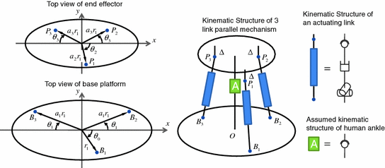

Fig. 8.2
Kinematic structure of the three-link parallel mechanism
In Fig. 8.2, the attachment points of the actuated links on the base are denoted by  while their attachments on the end effector are represented by
  . Based on the UPS link structure, point
  is coincident with the centre of the universal joint, while point
  is coincident with the centre of the spherical joint or equivalent on the
  th actuated link. Point
  had also been defined on the base platform where it acts as the origin of the robot global coordinate frame. The points
  and
and  are constrained to lie on the same plane and their relative positions are parameterised in polar coordinates. The projections of points
  on the end effector can similarly be represented in polar coordinates. In addition to that, the distance between
  and the end-effector plane is also set to be constant for all
  and is denoted by
  . Finally, the point
  is defined as the centre of the spherical joint used to represent the human ankle.
 while their attachments on the end effector are represented by
  . Based on the UPS link structure, point
  is coincident with the centre of the universal joint, while point
  is coincident with the centre of the spherical joint or equivalent on the
  th actuated link. Point
  had also been defined on the base platform where it acts as the origin of the robot global coordinate frame. The points
  and
and  are constrained to lie on the same plane and their relative positions are parameterised in polar coordinates. The projections of points
  on the end effector can similarly be represented in polar coordinates. In addition to that, the distance between
  and the end-effector plane is also set to be constant for all
  and is denoted by
  . Finally, the point
  is defined as the centre of the spherical joint used to represent the human ankle.
Using the proposed kinematic structure, the end effector can be seen to pivot about the actual ankle centre and not an external point. Consequently, when the shank is fixed on the base platform and the foot placed on the robot end effector, the robot would have completely isolated the ankle joint. Motion and moments of the end effector taken about the ankle centre will therefore, respectively, provide accurate indications of the relative orientation and moments between user’s foot and shank.
8.2.1.1 Inverse Kinematics
The inverse kinematics of a parallel mechanism is the mapping that relates a particular end-effector orientation to its corresponding joint displacements in terms of lengths of the actuated links. Such a relationship can be easily established using the kinematic parameters described above. By using the subscript 0 to represent quantities relating to the zero orientation, a pose where the end-effector orientation is identical with that of the robot global frame, the link vector ( ) of the
  th actuated link can be written as (8.2), while its length is given by (8.3).


 ) of the
  th actuated link can be written as (8.2), while its length is given by (8.3).
(8.2)

(8.3)
8.2.1.2 Computation of Reachable Workspace
Results obtained from the inverse kinematics are highly relevant for the determination of the workspace available in the parallel mechanism. Assuming that the passive joints have been selected so that the limiting factor on the robot workspace is solely that of the length of the actuated prismatic joint, an end-effector orientation can only pass as a point in the robot workspace if all the actuated link lengths fall within an allowable range. This range is typically controlled by the retracted and extended lengths of the linear actuator used in the link. For the purpose of initial analysis, it is assumed that the permissible ranges for the actuator lengths are centred about their respective values at the zero orientation. More precisely, the inequality denoting the constraint on actuated link lengths can be given as (8.4), where  is the maximum stroke length of the linear actuator and
  is the length of the
  th actuated link at the zero orientation.

 is the maximum stroke length of the linear actuator and
  is the length of the
  th actuated link at the zero orientation.
(8.4)
8.2.1.3 Computation of Singularity Measure
The manipulator Jacobian is a matrix which describes the relationship between joint space and task space velocities of a robot. For parallel mechanisms where a unique set of joint space coordinates can be assigned to a given task space configuration, the manipulator Jacobian  is the gradient matrix which relates the task space velocity
  to the joint space velocity
  as shown in (8.5). Note that
  is the total number of actuated links. It is also worth noting that the transpose of the manipulator Jacobian is used to relate the joint space forces
  to task space forces
  , as shown in (8.6). Analysis of the manipulator Jacobian can therefore provide information on the kinematics and kinetics of a robot at a particular configuration. The manipulator Jacobian for the proposed parallel kinematic structure can be obtained from differentiation of the inverse kinematics relationship shown in (8.2). Specifically, the
  th row of the manipulator Jacobian is given by (8.7).


![$$ J_{i} = \frac{1}{{l_{i} }}{L_{i}^{\text{T}}} \left[ {\begin{array}{*{20}c} {\frac{\partial R}{{\partial \theta_{x} }}P_{i,0} } & {\frac{\partial R}{{\partial \theta_{y} }}P_{i,0} } & {\frac{\partial R}{{\partial \theta_{z} }}P_{i,0} } \\ \end{array} } \right] $$](/wp-content/uploads/2016/09/A313541_1_En_8_Chapter_Equ7.gif)
 is the gradient matrix which relates the task space velocity
  to the joint space velocity
  as shown in (8.5). Note that
  is the total number of actuated links. It is also worth noting that the transpose of the manipulator Jacobian is used to relate the joint space forces
  to task space forces
  , as shown in (8.6). Analysis of the manipulator Jacobian can therefore provide information on the kinematics and kinetics of a robot at a particular configuration. The manipulator Jacobian for the proposed parallel kinematic structure can be obtained from differentiation of the inverse kinematics relationship shown in (8.2). Specifically, the
  th row of the manipulator Jacobian is given by (8.7).
(8.5)

(8.6)
![$$ J_{i} = \frac{1}{{l_{i} }}{L_{i}^{\text{T}}} \left[ {\begin{array}{*{20}c} {\frac{\partial R}{{\partial \theta_{x} }}P_{i,0} } & {\frac{\partial R}{{\partial \theta_{y} }}P_{i,0} } & {\frac{\partial R}{{\partial \theta_{z} }}P_{i,0} } \\ \end{array} } \right] $$](/wp-content/uploads/2016/09/A313541_1_En_8_Chapter_Equ7.gif)
(8.7)
An important role of the manipulator Jacobian is in the identification of singular configurations of the robot. Singular configurations are poses of the robot whereby the manipulator Jacobian is rank deficient. This means that singular configurations are generally related to an infinite condition number or zero matrix determinant (if the manipulator Jacobian is a square matrix). Rank deficiency in the manipulator Jacobian will lead to the loss of controllability of the robot, where the realisation of task space forces along certain directions will not be possible regardless of the joint space forces being applied. Alternatively, singular configurations can be viewed as poses where the manipulator gains additional degree(s) of freedom in motion since the presence of a null space in the manipulator Jacobian will allow certain task space velocities to exist even though all actuators are locked (i.e. joint space velocities is uniformly zero). Clearly, singular configurations are generally undesirable and must be eliminated from the workspace of the manipulator though selection of appropriate robot kinematic parameter. Even though singularities may only occur at certain points in the robot task space, it is also generally more difficult to control the robot at configurations around these singular points. As a result, a good design should aim to improve the manipulability of the robot by reducing the condition numbers of manipulator Jacobian across all points in the task space.
8.2.1.4 Force Analysis
As the transpose of the manipulator Jacobian also acts as a linear mapping between joint space and task space forces, it can be used to identify the actuator forces required to produce a particular task space moment. This normally involves the inversion of the manipulator Jacobian (or application of the pseudo-inverse if the manipulator is redundantly actuated). Clearly, the force requirements would change with the task space coordinates of the manipulator. The maximum desired moments were therefore applied at various end-effector configurations and the largest of the resultant joint space forces was treated as the actuator force specification. The configurations considered include the neutral position, a supinated (plantarflexed, inverted and adducted) foot configuration, a pronated (dorsiflexed, everted and abducted) foot configuration, and at configurations where a rotation close to the joint motion limit is made about one of the coordinate axes, while the displacements along the remaining two are kept at zero (i.e. pure dorsiflexion/plantarflexion, pure inversion/eversion and pure abduction/adduction).
8.2.1.5 Analysis Results and Discussion
Apart from the workspace, singularity and force requirements, the resultant design must also meet certain spatial constraints to ensure that it can be used in practice. Since the robot developed in this research is used for ankle rehabilitation, the kinematic parameters of the robot must be selected in such a way that it can accommodate the placement of the foot on the end effector. With this in mind, several sets of kinematic parameters for the proposed three-link parallel mechanism had been selected and analysed. The details of these kinematic parameters are provided in Table 8.2. The actuator force requirement, robot workspace and condition numbers of the manipulator Jacobians were computed for each of these designs, and the results of these are summarised in Table 8.3.
Table 8.2
Kinematic parameters of designs considered in the three-link manipulator analysis
Design ID |  (m) (m) |  |  |  |  |  |  |  |  (m) (m) |  (m) (m) |
|---|---|---|---|---|---|---|---|---|---|---|
A | 0.2 | 0.9 | 0.4 | 0.45 | −90° | 45° | −90° | 30° | 0.05 | ![$$ \left[ {\begin{array}{*{20}c} 0 \\ 0 \\ {0.36} \\ \end{array} } \right] $$](/wp-content/uploads/2016/09/A313541_1_En_8_Chapter_IEq95.gif) |
B | 0.11 | 0.7 | 0.75 | −90° | 30° | |||||
C | 0.2 | 0.3 | 0.35 | −90° | 30° | |||||
D | 0.2 | 0.5 | 0.55 | −90° | 30° | |||||
E | 0.2 | 0.4 | 0.45 | −60° | 30° | |||||
F | 0.2 | 0.4 | 0.45 | −90° | 45° |
Table 8.3
Design analysis results for different three-link designs
Design |  (N) (N) | Workspace | Manipulability |
|---|---|---|---|
A | 3119.1 | 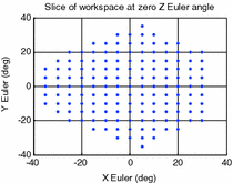 | 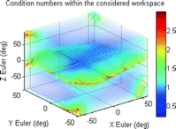 |
B | 6327.4 | 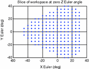 | 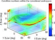 |
C | 4651 | 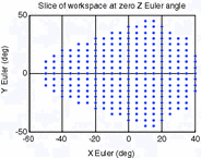 | 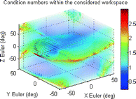 |
D | 4609.8 | 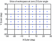 | 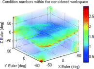 |
E | 3438.5 | 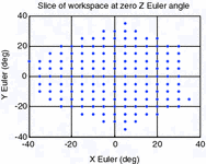 | 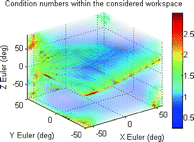 |
F | 2781.8 | 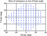 | 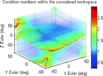 |
It can be seen from these results that the manipulator workspace is rather dependent on the separation of the attachment points on the end effector, where a decrease in separation will result in an increase in workspace volume. A look at the force requirements, however, suggests that smaller separation of attachment points can potentially lead to greater force requirements at certain end-effector configurations. In terms of the robot manipulability, it can be seen that a greater difference between the separation distances of attachment points on the base and end effectors can potentially lead to reduced condition numbers in the manipulator Jacobians. Another important observation is that a region of robot configurations with ill conditioned manipulator Jacobians, or in other words, low manipulability, appears to persist within the workspace for all the parameter sets considered.
For illustrative purposes, the results for one of these mechanisms (which kinematic parameters are given in Table 8.4) are shown in Figs. 8.3, 8.4 and 8.5. Figure 8.3 shows a slice of the robot workspace when the rotation about the Z Euler axis is zero. An inspection of this plot shows that this robot configuration can produce about 32° and 36° of maximum plantarflexion and dorsiflexion, respectively. Additionally, the maximum inversion–eversion motion is around 36°. A three-dimensional view of workspace volume is also shown in Fig. 8.4, and it can be seen that the largest range of motion of the robot is by far in the yaw direction, with maximum rotations of over 90°. A better visualisation of the task space with low manipulability is given in the volumetric plot shown in Fig. 8.5. In this plot, the condition numbers of the manipulator Jacobians at different orientations are represented in a colour spectrum and plotted on the three-dimensional axes.
Table 8.4


Kinematic parameters for the three-link parallel mechanism
Stay updated, free articles. Join our Telegram channel

Full access? Get Clinical Tree


