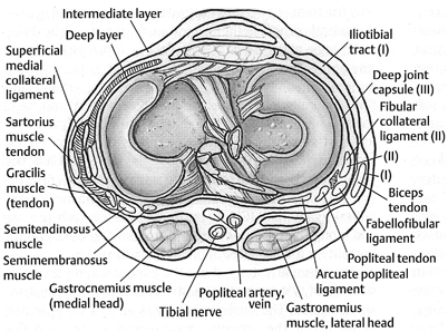
Fig. 18.1
Illustration depicting the anatomy of the posteromedial structures of the knee. (From [43]. Reprinted with permission from Thieme Publishers)
For the initial posteromedial approach to the knee, the patient is positioned supine on a flat operating room table. The incision is made along a line from the medial epicondyle to the insertion of the MCL along the posteromedial border of the tibia and the posterior aspect of the MCL. The knee should be flexed to approximately 70° and in the “figure-of-four” position for the deeper portions of the approach. Keeping the knee in this position relaxes the posterior neurovascular bundle and helps to avoid complications. Electrocautery may be used initially, followed by blunt dissection with Metzenbaum scissors to identify individual anatomic structures. The saphenous vein and nerve should be identified and protected if encountered, as injury has can frequently occur (Fig. 18.2). The sartorius fascia is exposed and incised in line with the incision and the pes anserinus tendons are identified and retracted distally. The fascia between the SM and medial head of the gastrocnemius is then identified and incised in line with the incision. The SM has multiple variable insertion points and occasionally requires release at its insertion along the medial aspect of the joint capsule, where it can be tagged for later repair. The medial head of the gastrocnemius should then be identified. This is an important step as the remainder of the approach remains anterior to this muscle, staying right on the posterior aspect of the proximal tibia and as close to the medial femoral condyle as possible. The medial head of the gastrocnemius is not typically released and all retractors should remain anterior and anterior to the popliteus muscle which is elevated directly off of the posterior tibia. Staying right on the bone and anterior to popliteus and gastrocnemius allows the surgeon to avoid injury to the posterior neurovascular structures. A Cobb or similar smooth instrument may be utilized to aid the dissection posterior to the joint capsule. The joint line should repeatedly be isolated so as not to dissect too far distally on the posterior tibial condyle. In the setting of a knee dislocation, the capsular structures may be completely disrupted, altering the normal anatomy posterior to the knee but also allowing direct exposure to the joint itself.
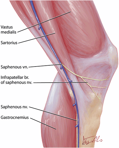

Fig. 18.2
Illustration depicting the anatomy of the saphenous vein and nerve in relation to the posteromedial structures of the knee
PCL Reconstruction
An anatomical PCL reconstruction combines the tibial inlay and two femoral tunnel techniques [34–37]. An Achilles tendon allograft is initially prepared on the back table, trimming the bone block to a length of 20 mm, a width of 15 mm, and a thickness of 10 mm, for a 20 × 15 × 10-mm inlay graft. It is necessary to have an adequate size bone block that is not too thin, as it could fracture when the screw is used to stabilize the bone block in the tibial trough. The tendinous portion is then divided sharply with a scalpel into a larger anterolateral bundle and a smaller posteromedial bundle (Fig. 18.3). A no. 2 nonabsorbable suture is then placed into each bundle using Krakow stitches. The notch is again debrided arthroscopically and, once this is complete, a femoral drill guide may be placed via the anteromedial portal. A guidewire is then drilled from outside-in approximately 10 mm from the articular surface as high in the notch as possible to represent the anterolateral tunnel. A second guidewire may then be placed inferior to the first, approximately 8 mm from the articular surface and far enough to allow at least a 4-mm bone bridge between tunnels (Fig. 18.4). Drilling of the anterolateral and posteromedial guidewires should be completed under direct visualization to ensure there is no change in the notch position during drilling. Each tunnel is subsequently reamed to its appropriate size. The tunnel sizes are determined by the size of the Achilles tendon allograft, with a goal of 8–9 mm for the anterolateral tunnel and 6–7 mm for the posteromedial tunnel. A shaver may be placed down the tunnels to remove any bony debris and to debride periosteum at the tunnel openings along the medial condyle to facilitate later screw placement. A nitinol wire is subsequently placed and each tunnel is tapped, respectively. If a 7- or 8-mm tunnel is reamed then either the same size or one size larger tap is utilized, depending on the bone quality.
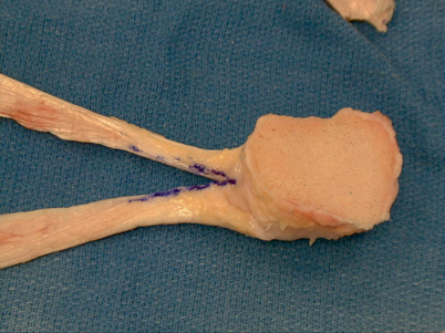
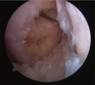

Fig. 18.3
Intraoperative photograph demonstrating the preparation of an Achilles tendon allograft for use in a posterior cruciate ligament reconstruction. (From [43]. Reprinted with permission from Thieme Publishers)

Fig. 18.4
Intraoperative photograph demonstrating the anterolateral and posteromedial tunnels drilled through the medial femoral condyle for a PCL reconstruction. PCL posterior cruciate ligament
A trough site similar in size to the bone block is then created in the posterior tibia, extending from approximately a centimeter distal to the posterior joint line and centered over the midline of the posterior tibia at the insertion site of the PCL . The trough may be created using a rongeur or small osteotomes, such as a 0.5-inch osteotome (Fig. 18.5). A blunt retractor, such as a Hohman, may be placed anterior to the popliteus and gastrocnemius across the posterior aspect of the tibia prior to making the trough to help retract the posterior structures. The knee may be flexed to 90° and the ankle externally rotated to aid in visualization of the posterior tibia. A 4.5-mm drill hole is drilled in the center of the bone block in a slightly oblique orientation from posteromedial to anterolateral. The block is subsequently fixed in the trough with a single 4.5-mm cannulated screw and washer (Fig. 18.6 18.6). A guidewire is initially utilized to hold the bone block in place and aimed at the tibial tubercle. In multiple ligament injuries, the guidewire may be directed more obliquely and laterally to avoid the tibial tunnel placement for ACL reconstruction. Fluoroscopy may be utilized to check guidewire placement and depth. A measurement may be taken directly from the guidewire, taking 8–10 mm off the measured depth for the screw length. The 4.5-mm screw and washer are then placed directly over the guidewire using lag technique (Fig. 18.7). Ideally, the bone block will be flush with the posterior tibia or just slightly proud, but not countersunk. A hole in the posterior capsule may then be made with a Kelly or similar pointed instrument (if posterior capsular damage is not already present from the dislocation) and the two bundles are advanced into the notch. This is accomplished with the aid of a Hewson suture passer, passed in the anteromedial portal, through the notch and out the posterior capsule. Graft passage is then completed under direct arthroscopic visualization. A small arthroscopic grasper is placed retrograde through the femoral tunnels and utilized to pass each graft, starting with the smaller, posteromedial bundle first. When passing the anterolateral graft, ensure that it remains on the lateral side of the previously passed posteromedial graft. A guidewire is again placed retrograde into each tunnel and the grafts are secured with absorbable interference screws the same size as was previously tapped. The anterolateral bundle should be tensioned at approximately 80° of flexion and the posteromedial tensioned at approximately 10° of flexion when final tensioning is performed.
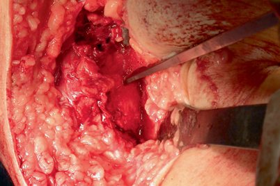
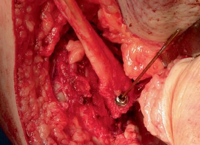
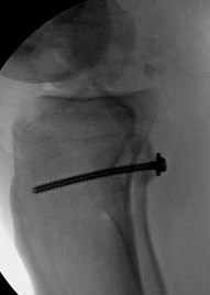

Fig. 18.5
Intraoperative photograph demonstrating preparation of the trough with an osteotome at the posterior aspect of the tibia for an inlay PCL reconstruction. PCL posterior cruciate ligament

Fig. 18.6
Intraoperative photograph demonstrating cannulated screw fixation of the tibial inlay bone block for a PCL reconstruction. PCL posterior cruciate ligament

Fig. 18.7
Lateral radiograph demonstrating screw fixation of the tibial bone block for a PCL reconstruction PCL posterior cruciate ligament
PMC Reconstruction
The senior author’s preferred technique for a PMC reconstruction in the setting of a combined ligament reconstruction utilizes either two semitendinosus grafts or one anterior or posterior tibialis allografts split in half to recreate the triangle of the MCL, POL, and the SM sling. The most preferable technique incorporates two semitendinosus allografts [38]. The grafts may be initially prepared with Krackow (or fiberloop) locking stitches placed at each end of both the grafts. The posteromedial dissection will have already been completed as described above. The isometric point of the knee is then found, either anatomically or radiographically. The radiographic method has been shown to have increased accuracy and is subsequently the method of choice of the senior author [39]. This is accomplished by obtaining a perfect lateral view of the knee using the fluoroscope, lining up the posterior femoral condyles. The isometric point is located where the extension of the posterior femoral cortical line intersects Blumensaat’s line (Fig. 18.8). The isometric point is the starting point for guide pin placement in the medial femoral condyle. A threaded guide pin may then be placed from medial to lateral. A cannulated reamer is placed over the guide pin to ream an 8 × 25-mm socket. An 8-mm absorbable biotenodesis screw (Arthrex, Naples, FL) is fixed to one end of each graft, forming two separate limbs, and placed in the femoral socket (Fig. 18.9). The tibial insertion site may then be prepared by using a rongeur to debride away the soft tissue just proximal and posterior to the insertion of the semitendinosus, all the way to bone. A 3.2-mm drill bit is utilized to drill a bicortical drill hole across the tibia in preparation for a 4.5-mm screw with a spiked ligament washer. The metal tibial screw and washer are provisionally placed, but not tightened all the way down to bone. A Kelly instrument is then passed deep to the SM from distal to proximal and the free end of the posterior limb of the graft is passed distally to the tibia (Fig. 18.10). The other free end of the graft (the anterior portion) is then passed directly inferior from its femoral insertion distally to the tibial screw in line with the MCL. Each limb of the graft is then passed around the tibial screw, beneath the washer, and a Cobb elevator is subsequently utilized to compress the tibial washer down while the screw is placed the rest of the way down and the graft is appropriately tensioned (Fig. 18.11). The screw is not compressed all the way down, however, until final tensioning is ready to be performed. This procedure reconstructs the superficial MCL (anterior limb of the graft) and the POL (posterior limb) (Fig. 18.12). The graft may tensioned at 30–40°of knee flexion , but again, not until all grafts for all reconstructions are in place. When the graft is finally tensioned, it should be isometric in flexion and extension. The remaining graft ends may be sutured together and sutured to the fixed graft using figure of eight stitches and then cut sharply to remove any excess graft material (Fig. 18.12). Attention is subsequently turned to the lateral side of the knee.
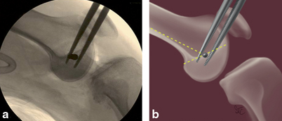
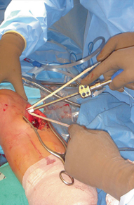
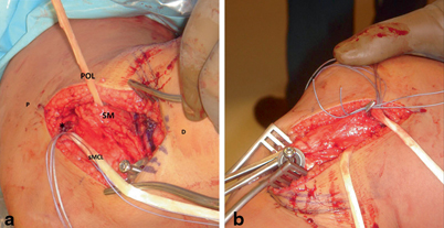
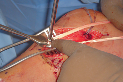
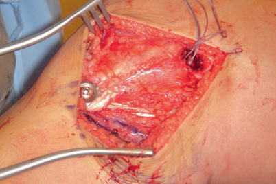

Fig. 18.8
a Lateral radiograph and b illustration demonstrating the isometric point of the knee

Fig. 18.9
Intraoperative photograph demonstrating proximal posteromedial corner graft fixation to the medial femoral condyle with a biotenodesis screw

Fig. 18.10
a, b Intraoperative photographs demonstrating passing of the posterior limb of the posteromedial corner reconstruction graft beneath the semimembranosus. (asterisk isometric point, P proximal, D distal, sMCL superficial MCL, POL posterior oblique ligament, SM semimembranosus)

Fig. 18.11
Intraoperative photograph demonstrating distal fixation of the posteromedial corner graft to the tibia with a screw and washer

Fig. 18.12
Intraoperative photograph demonstrating the completed posteromedial corner reconstruction
Posterolateral Approach and PLC Reconstruction
The PLC is primarily composed of: the fibular (lateral) collateral ligament, the popliteus muscle and tendon, the popliteofibular ligament, the lateral capsule, and variable structures such as the arcuate ligament and the fabellofibular ligament [40, 41]. Similar to the medial side of the knee, the lateral approach has been described in layers: Layer I is composed of the iliotibial tract and the biceps femoris. Layer II is composed of the patellar retinaculum and patellofemoral ligament and layer III is composed of the lateral collateral ligament (LCL ), fabellofibular ligament, arcuate ligament, popliteus tendon, popliteofibular ligament, and the joint capsule (Fig. 18.13). It is important to note that the common peroneal nerve typically lies between layers I and II. This nerve must always be isolated prior to deep joint exposure to prevent inadvertent injury. In order to relax and protect the nerve, the approach is best performed with the knee flexed. The incision is placed in line with the fibular head and continues in a straight line proximally. When proximally extended the incision may be carried out between the iliotibial band and biceps femoris tendon. The dissection is taken down to deep fascia with electrocautery, then careful dissection of the peroneal nerve is performed utilizing Metzenbaum scissors. The nerve can typically be palpated and isolated just proximal and posterior to the fibula and then released distally where it curves around the fibula in the soft spot just distal to the fibular head (Fig. 18.14). Once the nerve is identified, it may be protected with a vessel loop or a Penrose drain. The ends of the vessel loop or Penrose drain may be stapled together, but do not clamp or hang any instruments from them, as excessive retraction of the nerve from a hanging instrument can result in a neurapraxia. Blunt dissection is then utilized to establish the plane anterior to the lateral gastrocnemius head. In multiple ligament injuries, this dissection plane may already be formed secondary to the trauma from the injury. When this plane is not formed, however, the lateral gastrocnemius may be slightly more adherent to the posterior capsule, and care should be taken to retract it accordingly. Similar to the medial dissection being anterior to the medial gastrocnemius, no portion of the posterolateral dissection should occur posterior to the lateral gastrocnemius, as it would place the popliteal neurovascular structures at risk (Fig. 18.15). It is important to remember that the popliteal artery normally lies slightly lateral to midline at the level of the knee. Dissection may then be bluntly carried out along the posterior fibula and tibia and a Homann retractor may be carefully placed anterior to the lateral gastrocnemius. Once this dissection is complete, the PLC reconstruction may be performed.
