Cervical Orthopaedic Tests
Cervical Palpation
Anterior Aspect
Descriptive Anatomy
The sternocleidomastoid muscle extends from the mastoid process of the temporal bone down to the clavicle and sternum (Fig. 3-1). It divides the neck into anterior and posterior triangles. Its action is to flex the head to the same side and rotate it to the opposite side. Both muscles acting together flex the neck forward.
Procedure
Instruct the patient to turn the head to one side. Pinch the muscle on the side of head rotation between your thumb and forefinger, traveling from the clavicle upward to the mastoid (Fig. 3-2). Compare each muscle bilaterally, noting any inflammation, tenderness, and palpable bands. Palpable bands are hyperirritable spots within a taut band of skeletal muscle or fascia. Rate tenderness based on tenderness rating scale (Box 3-1).
Inflammation and tenderness secondary to trauma usually are associated with cervical acceleration and deceleration (CAD) types of injuries. Torticollis may also cause local inflammation and tenderness. Palpable bands may indicate a myofascial trigger point. These trigger points may be caused by overuse, trauma, or chilling. They may also indicate arthritic joints or emotional distress.
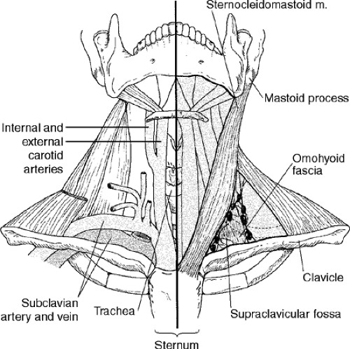 Figure 3-1 |
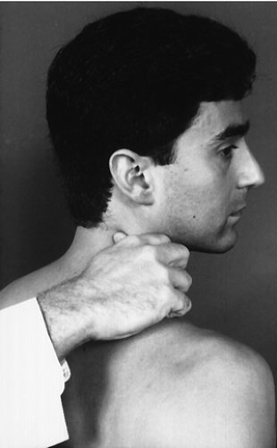 Figure 3-2 |
Descriptive Anatomy
The carotid arteries lie lateral to the trachea and medial to the sternocleidomastoid muscle. These arteries branch to form the internal and external carotid arteries, which supply blood to the brain (see Fig. 3-1).
Procedure
With your first and second digits, lightly press on the carotid artery against the transverse process of the cervical vertebra (Fig. 3-3). Palpate each artery individually and assess amplitude equality. A difference in the strength of the pulses may indicate carotid artery stenosis or compression. If carotid artery stenosis or compression is suspected, auscultate the carotid arteries for bruits and evaluate the vertebrobasilar circulation.
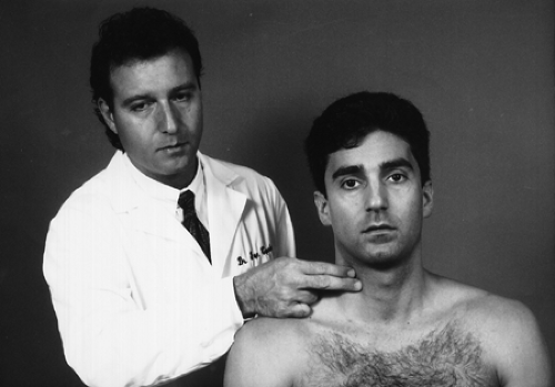 Figure 3-3 |
Descriptive Anatomy
The supraclavicular fossa is superior to the clavicle. It contains the omohyoid fascia, the lymph nodes, and the pressure point for the subclavian artery. It is usually a smooth, contoured depression (Fig. 3-1).
Procedure
Palpate each fossa for swelling, tenderness, and any abnormal bony or soft tissue masses (Fig. 3-4). Pain and tenderness associated with swelling secondary to trauma may indicate a fractured clavicle or a separated acromioclavicular joint. Abnormal bony tissue may indicate a cervical rib, which may cause neurological or vascular symptoms in the upper extremity. If an extra rib is suspected, evaluate for thoracic outlet syndrome (see Chapter 5). An abnormal soft tissue mass may indicate lymph adenopathy or a tumor.
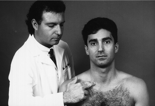 Figure 3-4 |
Posterior Aspect
Descriptive Anatomy
The trapezius muscle is a large, triangular muscle that extends from the occiput and spinous processes of the cervical and thoracic vertebra to the acromion process of the clavicle and spine of the scapula (Fig. 3-5). Its superior fibers elevate the shoulders; the middle fibers retract the scapula; and the inferior fibers depress the scapula and lower the shoulders.
Procedure
Palpate each muscle from the superior aspect just below the occiput downward, continuing to the superior aspect of the spine of the scapula, then lateral to the acromion process (Fig. 3-6). From the inferior, palpate from the spinous processes of the thoracic vertebra lateral and superior toward the acromion process (Fig. 3-7).
Inflammation and tenderness secondary to trauma may indicate muscle spasm caused by torn muscle fibers associated with edema. Inflammation and tenderness that are not trauma related may indicate fibrosis of muscle tissue or fibromyalgia. Assess it according to the tenderness rating scale (see Box 3-1). Palpable bands indicate myofascial trigger points that may be caused by overuse, overload, trauma, or chilling. These palpable bands may also indicate arthritic joints or emotional distress.
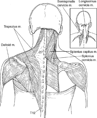 Figure 3-5 |
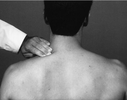 Figure 3-6 |
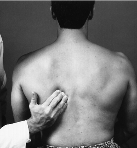 Figure 3-7 |
Descriptive Anatomy
The palpable intrinsic spinal muscles in the cervical spine consist of splenius capitis and cervicis, longissimus cervicis, and semispinalis cervicis. These layered muscles are used for the maintenance of posture and movements of the cervical spine. The superficial layer consists of the splenius capitis and cervicis, and the intermediate layer consists of the longissimus and semispinalis cervicis. These muscles stretch from the base of the occiput to the upper aspect of the thoracic spine (Fig. 3-5). The deep muscles on the cervical spine at best are difficult to palpate and are not discussed here.
Procedure
Palpate the superficial layer by moving the fingers in a transverse fashion over the belly of the muscle with the cervical spine in slight extension (Fig. 3-8). Note any abnormal tone, tenderness, or palpable bands. Palpate the intermediate layer with the fingertips directly adjacent to the spinous processes, also with the cervical spine in slight extension (Fig. 3-9). Note any abnormal tone, tenderness, or palpable bands. Rate the layers according to the tenderness rating scale (Box 3-1). Any abnormal tone or tenderness may indicate an inflammatory process in the muscle, such as muscle strain, myofascitis, or fibromyalgia. Palpable bands indicate myofascial trigger points, which may be caused by overuse, overload, trauma, or chilling. They may also indicate arthritic joints or emotional distress.
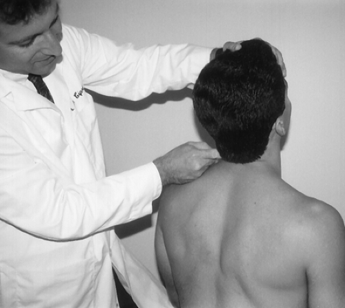 Figure 3-8 |
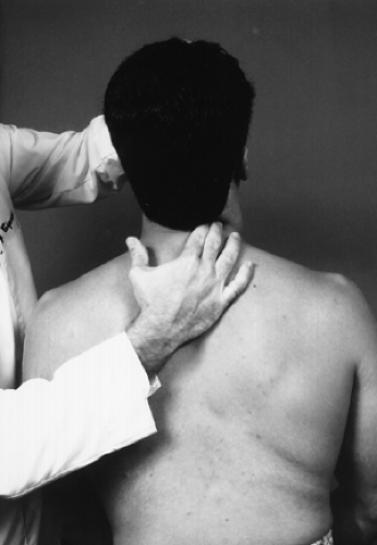 Figure 3-9 |
Descriptive Anatomy
The C1, or atlas, vertebra has a posterior arch rather than a spinous process that is difficult at best to palpate. The C2 to C7 vertebrae have relatively prominent spinous processes that are easily palpable. Slightly lateral to the spinous processes lie the facet joints. Each facet joint is composed of a posterior inferior articular process and a posterior superior articular process from congruent vertebra (Fig. 3-10).
Procedure
With the patient seated and head slightly flexed, palpate each spinous process individually with your index and/or middle finger, noting any pain and/or tenderness (Fig. 3-11). Also, evaluate each spinous process as you move the cervical spine in flexion and extension to determine hypomobility versus hypermobility (Fig. 3-12).
Again, with the patient’s head slightly flexed, using your thumb and index finger, palpate the facet joints bilaterally both in a static position (Fig. 3-13) and in a flexed position while performing extension movements (Fig. 3-14). Tenderness at the spinous and/or facet joint indicates an inflammatory process at that site. The inflammation is usually secondary to subluxation or trauma, that is, hyperflexion or hyperextension injury. Crepitus on movement may indicate degenerative joint disease.
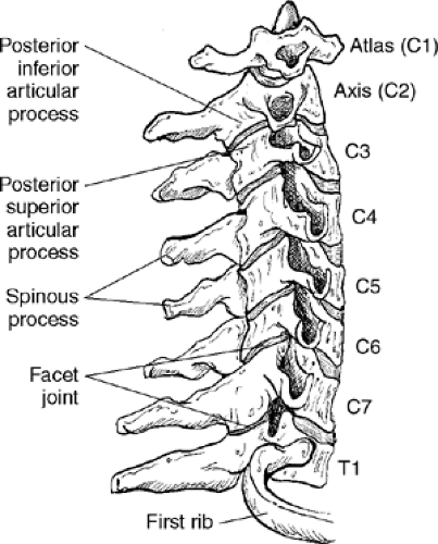 Figure 3-10 |
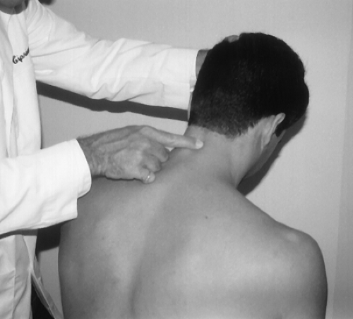 Figure 3-11 |
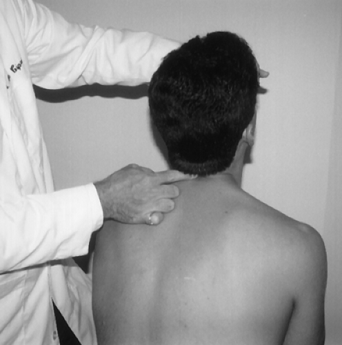 Figure 3-12 |
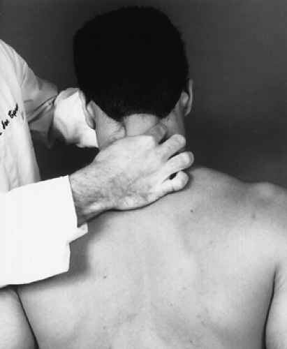 Figure 3-13 |
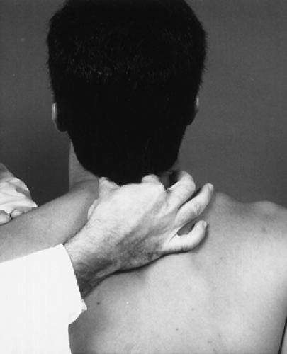 Figure 3-14 |
Cervical Range of Motion
Cervical range of motion should be evaluated only after taking a proper and thorough history to rule out any indication that these movements will adversely affect the patient. Severe trauma causing a fracture or dislocation or cervical vascular compromise should be ruled out before performing these movements. You should not only note limited motion in the cervical spine but also any pain along with its location and character. The most painful movements should be performed last so that no residual pain is carried over from the previous movement. Crepitus should also be noted upon movement; it may indicate degenerative changes in the cervical spine.
Spinal range of motion is measured using inclinometers, with the patient performing the movements actively and passively. The inclinometer is the preferred instrument for measuring spinal range of motion because it measures angular displacement relative to gravity. For continuity of reporting and for evaluating patient compliance, the movements should be performed three times. The three measurements must be within 5° or 10% of each other for a valid reporting criterion. The full arc of motion is paramount to the evaluation of range of motion in the cervical spine. Adding the opposing measurements to determine the full arc of movement is the most objective way to assess cervical spine movement. For example, the patient carries the head in 10° of flexion, which for this person is the neutral position. When you measure cervical flexion on this individual, cervical flexion may be reduced 10° from average. If you then measure extension, you may possibly have an increase of 10°. This increase may be caused by the 10° flexion angle, which is the neutral position for that patient. If you take each measurement individually, you have a deficit movement in flexion and an increase in movement in extension. If you add both movements, you see that the full arc is within normal limits.
With the patient seated and the cervical spine in the neutral position, place one inclinometer over the T1 spinous process in the sagittal plane. Place the second inclinometer at the superior aspect of the occiput, also in the sagittal plane (Fig. 3-15). Zero out both inclinometers. Instruct the patient to flex the head forward and record both angles (Fig. 3-16). Subtract the T1 inclination from the occipital inclination to obtain the active cervical flexion angle.
Normal Range
Normal range is 50° or greater from the neutral or 0 position for active movement.
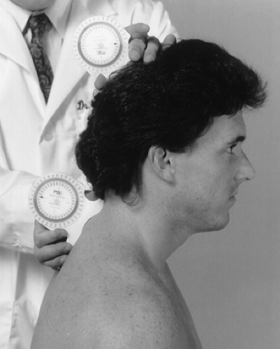 Figure 3-15 |
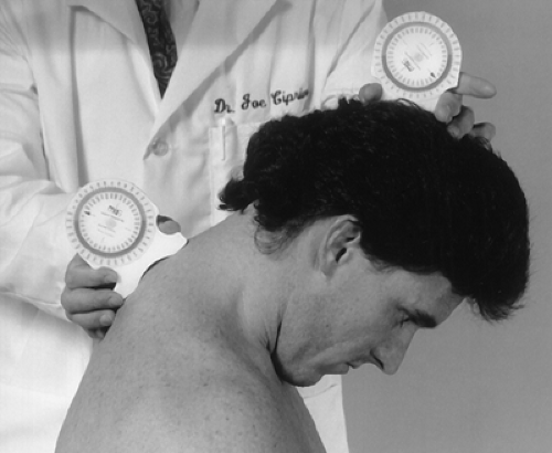 Figure 3-16 |
With the patient seated and the cervical spine in the neutral position, place one inclinometer slightly lateral to the T1 spinous process in the sagittal plane. Place the second inclinometer at the superior aspect of the occiput, also in the sagittal plane (Fig. 3-17). Zero out both inclinometers. Instruct the patient to extend the head backward and record both inclinations (Fig. 3-18). Subtract the T1 inclination from the occipital inclination to obtain the active cervical extension angle.
Normal Range
The normal range is 60° or greater from the neutral or 0 position for active movement and 110° for full arc of active flexion and extension. The normal range of passive flexion and extension varies as follows (3):
| Age | Degrees |
|---|---|
| 20–29 | 151 ± 17 |
| 30–49 | 141 ± 35 |
| > 50 | 129 ± 14 |
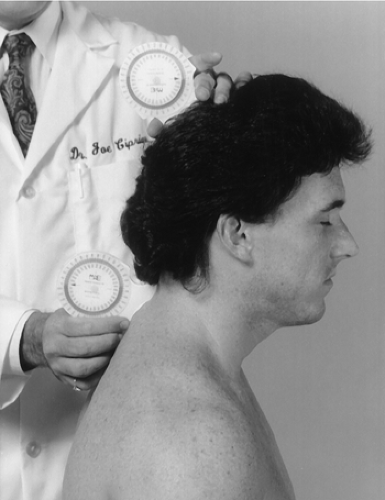 Figure 3-17 |
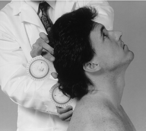 Figure 3-18 |
With the patient seated and the cervical spine in the neutral position, place one inclinometer flat on the T1 spinous process in the coronal plane. Place the second inclinometer at the superior aspect of the occiput, also in the coronal plane (Fig. 3-19). Zero out both inclinometers. Instruct the patient to flex the head to one side and record both inclinations (Fig. 3-20). Subtract the T1 inclination from the occipital inclination to obtain the active cervical lateral flexion angle. Repeat with flexion to the opposite side.
Normal Range
The normal range is 45° or greater from the neutral or 0 position for active movement and 90° for full arc of active right and left lateral flexion. The full arc of passive right and left lateral flexion varies as follows (3):
| Age | Degrees |
|---|---|
| 20–29 | 101 ± 11 |
| 30–49 | 93 ± 13 |
| > 50 | 80 ± 17 |
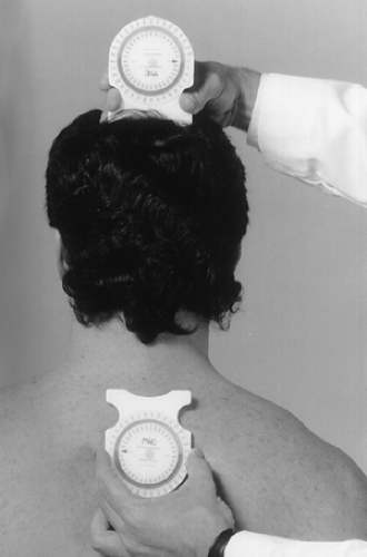 Figure 3-19 |
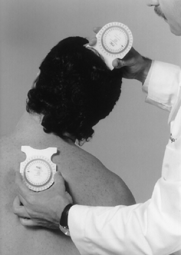 Figure 3-20 |
With the patient supine, place the inclinometer at the crown of the head in the transverse plane (Fig. 3-21). Zero out the inclinometer. Instruct the patient to rotate the head to one side, and then record your findings (Fig. 3-22). Repeat the procedure with the patient’s head rotated to the opposite side.
Normal Range
Normal range is 80° or greater from the neutral or 0 position for active movement. The full arc of active right and left rotation is 160°. The full arc of passive right and left rotation varies as follows (3):
| Age | Degrees |
|---|---|
| 20–29 | 183 ± 11 |
| 30–49 | 172 ± 13 |
| > 50 | 155 ± 15 |
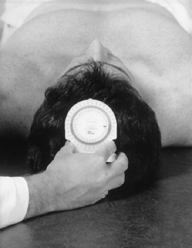 Figure 3-21 |
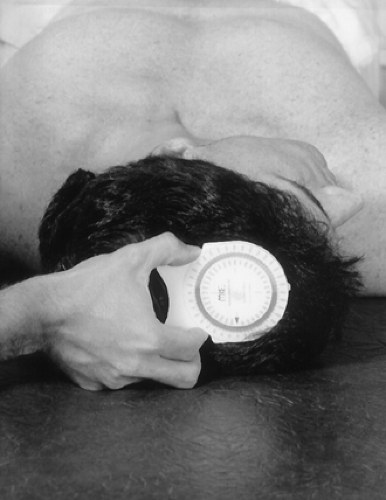 Figure 3-22 |
Cervical Resistive Isometric Muscle Testing
The same movements can also be tested for resistive strength. Contraindications such as fracture, dislocation, and cervical vascular compromise must be considered before testing for resistive strength.
Resistive isometric muscle testing is performed to evaluate muscle strength or muscle state. Weakness of a particular muscle or muscle group may indicate neurological dysfunction in the nerves supplying the affected muscles. Pain of a particular muscle or muscle group during resistive isometric muscle testing may indicate muscle dysfunction, such as a muscle strain.
Each of the following movements includes a chart that indicates the muscles that make the movement and the nerve supply to each muscle. The clinician evaluates each movement according to muscle strength; grade is based on the muscle grading scale adopted by the American Academy of Orthopaedic Surgeons (Box 3-2).
Box 3-2 Muscle Grading Scale
| 5 | Complete range of motion against gravity with full resistance |
| 4 | Complete range of motion against gravity with some resistance |
| 3 | Complete range of motion against gravity |
| 2 | Complete range of motion with the gravity eliminated |
| 1 | Evidence of slight contractility; no joint motion |
| 0 | No evidence of contractility |
Flexion
With the patient seated and in the neutral position, instruct him or her to flex the head forward against your resistance, making sure that there is no patient movement and only muscle contraction (Fig. 3-23).
| Muscles | Nerve Supply |
|---|---|
| 1. Longus colli | C2–C5 |
| 2. Scalenus anterior | C4–C5 |
| 3. Scalenus medius | C3–C8 |
| 4. Scalenus posterior | C6–C8 |
| 5. Sternocleidomastoid | Accessory, C2 |
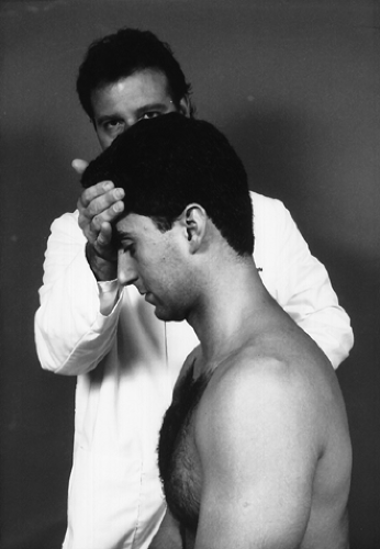 Figure 3-23 |
Extension
With the patient seated and in the neutral position, instruct him or her to extend the head backward against your resistance, making sure that there is no patient movement and only muscle contraction (Fig. 3-24).
| Muscles | Nerve Supply |
|---|---|
| 1. Splenius cervicis | C6, C7, C8 |
| 2. Semispinalis cervicis | C1–C6, C7, C8 |
| 3. Longissimus cervicis | C6–C8 |
| 4. Levator scapulae | C3–C4 |
| 5. Iliocostalis cervicis | C6, C7, C8 |
| 6. Spinalis cervicis | C6, C8 |
| 7. Multifidus | C1–C6, C7, C8 |
| 8. Interspinalis cervicis | C1–C8 |
| 9. Trapezius (Upper) | C3, C4 |
| 10. Rectus capitis posterior major | C1 |
| 11. Rotatores breves | C1–C8 |
| 12. Rotatores longi | C1–C8 |
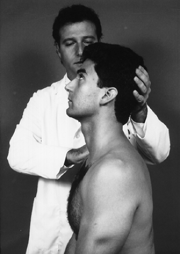 Figure 3-24 |
Lateral Flexion
With the patient seated and in the neutral position, instruct him or her to bend the head to one side against your resistance, making sure that there is no patient movement and only muscle contraction (Fig. 3-25). This action should be performed bilaterally.
| Muscles | Nerve Supply |
|---|---|
| 1. Levator scapulae | C3–C4 |
| 2. Splenius cervicis | C4–C6 |
| 3. Iliocostalis cervicis | C6–C8 |
| 4. Longissimus cervicis | C6–C8 |
| 5. Semispinalis cervicis | C1–C8 |
| 6. Multifidus | C1–C8 |
| 7. Intertransversarii | C1–C8 |
| 8. Scaleni | C3–C8 |
| 9. Sternocleidomastoideus | C2 |
| 10. Obliquus capitis inferior | C1 |
| 11. Rotatores breves | C1–C8 |
| 12. Rotatores longi | C1–C8 |
| 13. Longus colli | C2–C6 |
| 14. Trapezius | C3–C4 |
 Figure 3-25 |
Rotation
With the patient seated and in the neutral position, instruct him or her to rotate the head to one side against your resistance, making sure that there is no patient movement and only muscle contraction (Fig. 3-26). This action should be performed bilaterally.
| Muscles | Nerve Supply |
|---|---|
| Moves Face to Same Side | |
| 1. Levator scapulae | C3–C4 |
| 2. Splenius cervicis | C4–C6 |
| 3. Iliocostalis cervicis | C6–C8 |
| 4. Longissimus cervicis | C6–C8 |
| 5. Intertransversarii | C1–C8 |
| 6. Obliquus capitis inferior | C1 |
| 7. Rotatores breves | C1–C8 |
| 8. Rotatores longi | C1–C8 |
| Moves Face to Opposite Side | |
| 1. Multifidus | C1–C8 |
| 2. Scaleni | C3–C8 |
| 3. Sternocleidomastoideus | C2 |
Rationale
Pain on resistive isometric contraction may indicate a musculotendinous strain of one or more of the muscles involved in the action. Weakness may indicate a neurological disruption to the muscle or muscles involved in the action.
 Figure 3-26 |
Vertebrobasilar Circulation Assessment
Clinical Description
Vascular insufficiency may be aggravated by positional change in the cervical spine. Assessment of vertebrobasilar circulation must be done if cervical adjustment or manipulation is to be performed. Absolute contraindications and risks of cervical adjustment or manipulation can be minimized significantly, even though reportedly small, with proper diagnostic evaluation. These risks and contraindications may be predicted in some cases by functional or provocative testing and by adequate history (familial history of stroke or cardiovascular disease, hypertension, smoking, cervical spondylosis or arthrosis, bleeding disorders, medication, and/or anatomic anomaly or pathology). Vascular accidents may still occur with no evidence of vascular insufficiency, deficit, and negative provocative procedures. Box 3-3 lists the eight most common predispositions associated with cerebrovascular accidents.
Box 3-3 Predispositions To Cerebrovascular Accidents
Headaches, migraine
Dizziness
Sudden severe head or neck pain
Hypertensive
Cigarette smoking
Oral contraceptives
Obesity
Diabetes
All of the following tests incorporate a positional change in the cervical spine. The rotation aspect of this change is the common denominator of all the following tests. Rotation of C1 on C2 between 30° and 45° compresses the vertebral artery at the atlantoaxial junction on the opposite side of head rotation, reducing blood flow to the basilar artery (Fig. 3-27) (4,5). In the normal patient, this diminution of blood flow caused by positional change of the cervical spine does not cause any neurological symptoms, such as dizziness, nausea, tinnitus, faintness, or nystagmus. This lack of symptoms is a result of the normal flow of collateral circulation by the opposite vertebral artery, common carotid arteries, and a communicating cerebral arterial circle (Circle of Willis) (Fig. 3-28).
Rotational instability in the upper cervical spine caused by trauma, arterial artery disease, and/or degenerative joint disease in the cervical spine may lead to a mechanical reduction of blood flow to an area, causing neurological symptoms. This reduction of blood flow may be such that the collateral circulation is not sufficient to sustain normal function to the brain. Therefore, when you positionally stress a vessel in the cervical spine, you are testing the integrity of the collateral circulation supplied to the area, which is normally supplied by the vessel being stressed.
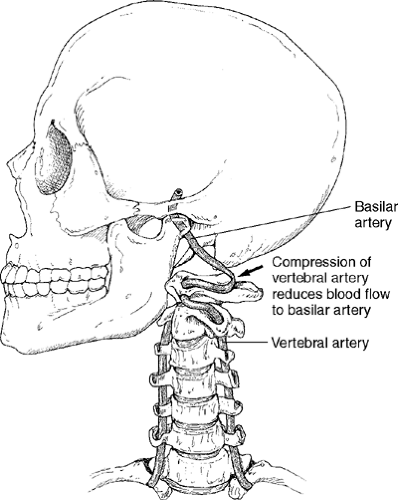 Figure 3-27 |
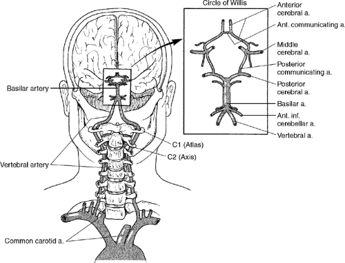 Figure 3-28 |
Assessment of the vertebrobasilar circulation by provocative or functional testing stresses seven areas of possible compression. These areas are as follows (Fig. 3-29):
Between C1 and C2 transverse processes, where the vertebral arteries are relatively fixed at the C1 and C2 transverse foramina
C2 to C3 at the level of the superior articular facet of C3 on the ipsilateral side to head rotation
The C1 transverse process and the internal carotid artery
The atlanto-occipital aperture by the posterior arch of Atlas and the rim of foramen magnum or anteriorly at the atlanto-occipital joint capsule and posteriorly at atlanto-occipital membrane.
C4 to C5 or C5 to C6 levels because of arthrosis of the joints of the uncovertebral joints with compression on the ipsilateral side to head rotation
At the transverse foramina of the atlas or axis between the obliquus capitis inferior and intertransversarii during rotatory movements
Before entering the C6 transverse process by the longus colli muscle or by tissue communicating between the longus colli and scalenus anterior muscles
Most compression and/or damage is reported at the first four sites.
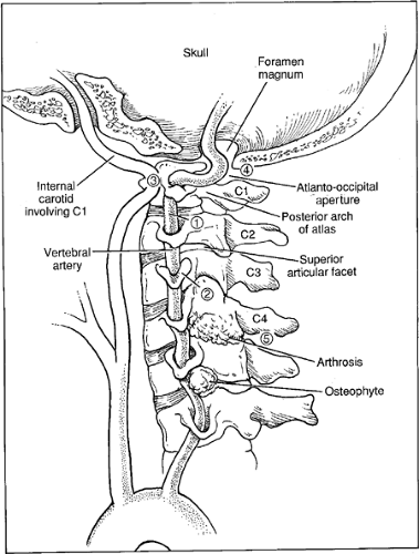 Figure 3-29 |
Allow a 10-second interval between tests to ensure that there are no latent symptoms. If symptoms are reproduced, there is no need to progress to any other cervical vascular provocative tests. The most common clinical signs and symptoms exhibited in cerebrovascular episodes are presented in the box below.
Clinical Signs and Symptoms of Cerebrovascular Episodes
Vertigo, dizziness, giddiness, light-headedness
Drop attacks, loss of consciousness
Diplopia
Dysarthria
Dysphagia
Ataxia of gait
Nausea, vomiting
Numbness on one side of the face
Nystagmus
Barré-Liéou Sign (6)
 |
Procedure
Related posts:

Stay updated, free articles. Join our Telegram channel

Full access? Get Clinical Tree


