CHAPTER 78 Biomechanics of the Intervertebral Disc
INTRODUCTION: STRUCTURE AND FUNCTION OF DISC
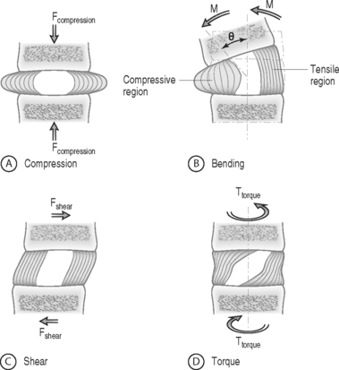
The intervertebral disc separates the rigid vertebral bodies and allows for large, complex, three-dimensional motion of the spine. The disc, therefore, must be soft enough to permit spinal motions of axial compression, flexion–extension, lateral bending, and axial rotation, all of which subject the disc to compressive, bending, shear, and torsional forces, respectively (Fig. 78.1). At the same time, the disc must be stiff enough to maintain stability and withstand the large loads encountered as the lumbar spine progresses through the physiologic motions required by daily living. This is accomplished in part by the disc’s unique ability to absorb and dissipate energy that is generated during these activities. Clearly, the primary function of the disc is mechanical. Therefore, an appreciation of normal and degenerative disc biomechanics is critical to understanding the etiology and sequelae of disc disease, as well as the consequences of intervention.
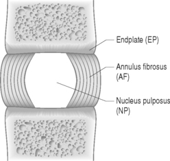
The disc is composed of substructures which are themselves distinct tissues: the nucleus pulposus, anulus fibrosus, and cartilaginous endplates (Fig. 78.2).1 The composition and structure of these disc components are summarized briefly below.
When the disc degenerates, its biochemical, cellular, structural, and mechanical functions are compromised. Some of these changes include anulus fibrosus fissures and tears, nucleus pulposus loss of proteoglycan and depressurization, endplate calcification and failure, and cell senescence and death.2 Despite the widely accepted notion that disc degeneration is an important potential source of back pain, a clear link between disc pathology and back pain has not yet been established. Further, a clear distinction between physiologic aging of the disc and disc degeneration has not been delineated. Nevertheless, while the precise mechanisms by which the disc may produce back pain have yet to be identified, disc degeneration is considered an important potential source of pain and the subject of continued intense investigation.3,4
BASIC BIOMECHANICS
Basic biomechanics terminology
Biomechanics deals with the study of forces and displacements acting on biological materials and their resulting effects. In this section, basic biomechanical terminology and principles are defined and applied to the disc. A more detailed explanation of these biomechanical concepts can be found in two excellent texts written for nonengineers by Low and Read5 and Panjabi and White.6
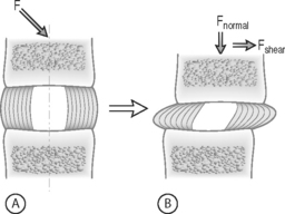
FORCE: Force is an action that moves or deforms a body – a push or a pull. It is a vector quantity often depicted using an arrow which indicates a magnitude, direction, and a point of application. Figure 78.3 demonstrates these actions applied to a spinal motion segment. The unit of force is a Newton. Complex forces are usually broken down into their ‘components.’ For example, the generic applied force in Figure 78.3A is broken down into its components of normal force and shear force as shown in Figure 78.3B.
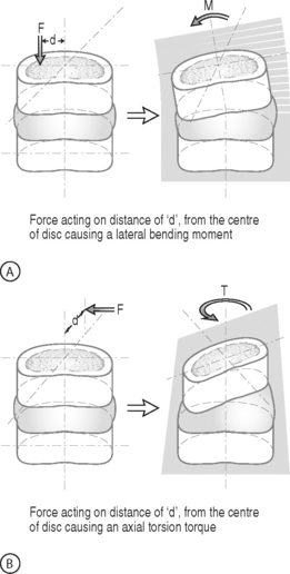
BENDING MOMENT OR TORQUE: When a force is applied at some distance from the center of an object it may cause a bending or turning effect, which is known as a moment or a torque (Fig. 78.4). Moment and torque are both defined as the magnitude of the force times the lever arm (the perpendicular distance between the force and the chosen center of rotation). The units for bending and torque are N-mm or N-m, depending on the scale of the objects considered. Bending moment and torque are the same except that generally in bending the force and lever arm are in the plane parallel to the axis of the structure (Fig. 78.4A), while for a torque they are perpendicular to the axis of the structure (Fig. 78.4B). An example of a bending moment is forward flexion, where the weight of the upper body times its distance from the spine is the applied bending moment. An example of torque is the torso twisting along the long axis of the body. Another example is when a screwdriver is turned; in this case, the force applied to the handle times the diameter of the handle is the torque. The clinical application of moments and torques in the spine explains how seemingly small forces may generate significant moments as a result of large lever arms.
STRESS: Force is generally not applied at a single point, but is distributed over a contact area. This distribution of force, or load intensity, is defined as stress. Stress is the ratio of force divided by the area of application and usually has the units of N/mm2 (MPa or Megapascals) or N/m2 (Pascals), depending on the size scale. Stress is sometimes defined in Imperial units as pounds per square inch (psi). Stress can be broken down into its components, as is done for force. The force components shown in Figure 78.3B, when divided by the disc surface area, can be used to calculate the applied compressive and shear stress. Externally applied stresses on an object give rise to internal stresses.
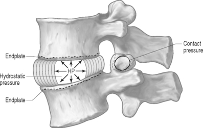
PRESSURE: There are two types of pressures: contact pressure and fluid pressure (Fig. 78.5). Contact pressure occurs in solids and is an applied compressive stress. For example, the contact of the two facet joint surfaces imposes a compressive stress that is sometimes called a contact pressure. Importantly, fluid pressure, also known as hydrostatic pressure, occurs in contained fluids and should not be confused with solid stress or contact stress, even though it has the same units. Fluid pressure is the intensity of loading within a contained fluid. The fluid pressure is generated by the interactions of the fluid molecules with the surface of its container. Hydrostatic pressure is isotropic, which means that it is the same in all directions. The nucleus pulposus of the disc is considered to be a fluid (or fluid-like) substance and therefore generates a hydrostatic pressure when the disc is loaded. This pressure is the same in all directions: vertically against the endplates and radially against the containing walls of the anulus fibrosus, as shown in Figure 78.5.
Soft tissue mechanical behaviors
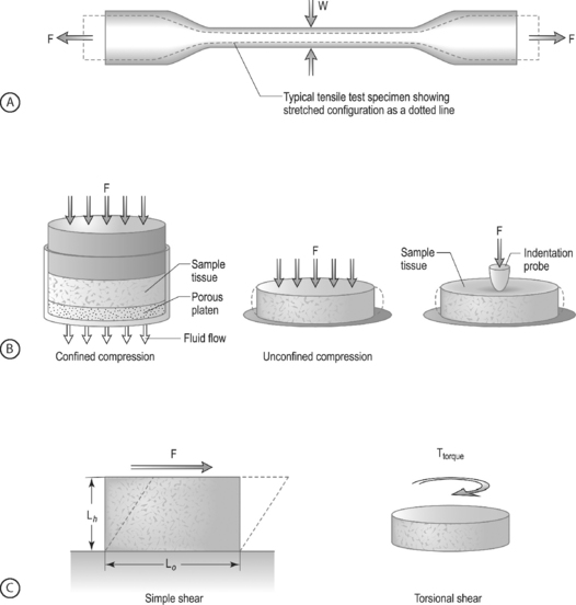
LOADING CONFIGURATIONS: There are three standard mechanical testing configurations for soft tissues: tension, compression, and shear. For tension and compression experiments the specimen ends are pulled away from each other (tension) or pushed towards each other (compression). In a tension test, the specimen is generally long and thin (Fig. 78.6A) and is held in the testing machine at both ends. The specimen ends are pulled apart leading to an increase in the length and decrease in width. In a compression test, the sample is generally a short cylinder, and the two ends of the specimen are pushed towards each other resulting in a decrease in the height of the specimen (Fig. 78.6B). For shear loading tests, a sample may be either rectangular or cylindrical and the load is applied parallel to the surface (Fig. 78.6C). The sample then changes its shape without undergoing either compression or tension.
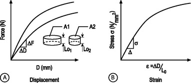
STRUCTURAL AND MATERIAL PROPERTIES: A biomechanical study typically involves experimentation and curve-fitting to a mathematical equation to determine the relationship between the force and displacement. However, for specimens of the same material with different dimensions, the force–displacement curves will be different, as shown in Figure 78.7A. This is because both force and displacement are ‘as measured’ quantities and not normalized with respect to the specimen geometry (e.g. cross-sectional area and height). Thus, it is important that the data for force and displacement be normalized to enable comparisons among different-sized samples. These principles have led to the development of normalized quantities such as stress and strain. The stress–strain response of the same material prepared into samples of different sizes is the same (Fig. 78.7B). The slope of this curve is defined as the modulus of the material and has the units of MPa or N/mm2. Similarly, the slope of the force versus displacement curve is defined as the stiffness and has the units of N/mm. For tension and compression testing, Poisson’s ratio is defined as the negative of the lateral contraction strain divided by the applied longitudinal strain. In shear testing, the shear modulus is calculated as the slope of the shear stress (applied parallel to the sample surface) versus the angle of displacement.
NONLINEARITY: A material is nonlinear if the force–displacement or stress–strain response does not have constant slope. While many materials are linear, most biological materials are nonlinear. Consequently, a single stiffness or modulus cannot describe the tissue’s behavior over all loading levels. In motion segment mechanics, this nonlinearity is exemplified by the dramatically different behavior in the low-stiffness neutral zone compared to the high-stiffness loading zones (Fig.78.8A). In soft tissue mechanics, nonlinearity is observed by the low ‘toe region’ modulus and the larger ‘linear region’ modulus (Fig. 78.8B). The large differences in compressive and tensile properties are another form of material nonlinearity.
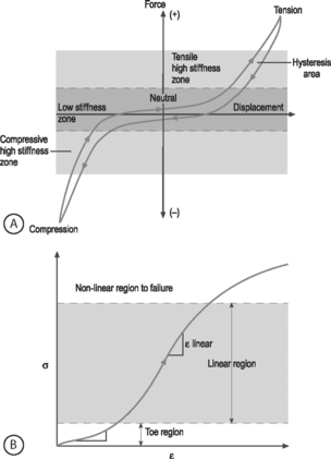
Nonlinearity in a spine motion segment is observed as the very large changes in stiffness as the motion segment is moved through the range of motion in any single loading direction. This is an important mechanical behavior because it contributes to the overall range of motion and because an increase in the neutral zone length is consistently observed in degenerated discs.7 A typical cyclic load response of an intervertebral disc is shown in Figure 78.8A. The curve is characterized by high stiffness regions at the extreme ends of loading and by a low stiffness region at low loads. The region of the response in the low load (or moment) and low deformation (or rotation) region is called the ‘neutral zone.’ The neutral zone is defined as the region on either side of the neutral position where there is little or no resistance to motion.7,8 The neutral zone mechanical properties are used to understand the stability of the disc motion segment. Although early studies reported the neutral zone as simply the displacement (rotation) over which loads (moments) are negligible, recent studies have focused on quantifying this important region of disc mechanical function.9,10
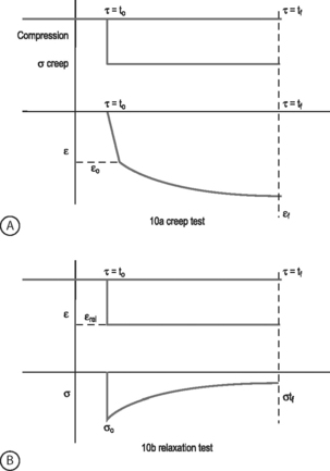
VISCOELASTICITY: All biological tissues, including disc, bone, cartilage, muscle, tendon, and ligaments, exhibit viscoelastic behaviors. A material is viscoelastic if it has time-dependent mechanical behaviors. For example, if a constant compression load (load-control) is applied to a spine segment it will immediately deform (the elastic response) and it will slowly continue to deform over the next several minutes and hours (the viscous response). The most commonly used test to evaluate tissue viscoelasticity in the spine is called a creep test (Fig. 78.9A). The analogous test applied under a constant displacement (displacement-control) is called a stress-relaxation test (Fig. 78.9B). In this case, a constant displacement is applied to the spine segment which immediately experiences a stress (the elastic response). Over the next few minutes or hours, the segment relaxes to a lower stress value (the viscous response). In a viscoelastic experiment, the stress (relaxation) or strain (creep) data are applied to a best-fit curve, the constants from which permit comparisons among different specimens. Another viscoelastic response is hysteresis, which describes a difference of cyclic loading in the load-displacement curve in the loading and unloading phases. The intervening area in this curve is described as the hysteresis area, and represents energy lost as heat due to viscous effects (see Fig. 78.8A).
TISSUE MECHANICS OF DISC SUBSTRUCTURES
Nucleus pulposus mechanics
The nucleus pulposus is a highly hydrated gel with important material properties that include swelling pressure, compression modulus, permeability, and shear modulus. The nucleus has a large water and proteoglycan content. Proteoglycans have negatively charged glycosaminoglycans attached, which attract positive ions and generate high osmotic pressures. If the nucleus pulposus is removed and placed in a hydrating solution it swells to at least two times its volume. The nucleus swelling pressure has been measured using a pressure transducer in vivo and in excised cadaveric spines under mechanical loading. The swelling pressure of a healthy nucleus is 0.1–0.2 MPa in a recumbent position and may reach as high as 1–3 MPa when standing or lifting.11,12 Similarly high pressures have been measured in cadaveric motion segments under externally applied loads.13,14 The swelling pressure has also been measured using osmometry methods15 and in confined compression,16 producing values consistent with in vivo measurements. The nucleus pulposus swelling pressure has been shown to be correlated with the glycosaminoglycans content.15,16
The large propensity of the nucleus pulposus to swell makes it difficult to prepare test samples and to measure its mechanical properties. As a result, there is a paucity of studies in the literature which have examined these properties. This dearth of mechanical data has made it difficult to properly model the nucleus pulposus in finite element studies of the spine. Lack of mechanical data has also hampered the development of tissue-engineered and artificial disc replacements because clear targets for mechanical function are needed. Fortunately, recent studies have provided measures of the tissue properties and their changes with degeneration. The equilibrium shear modulus of nondegenerate human nucleus pulposus is 0.2 kPa and increases to 0.6–0.8 kPa with degeneration.17 The high water content of the nucleus pulposus contributes to the large viscoelastic effects observed. Further, the dynamic shear modulus is almost two orders of magnitude larger than the equilibrium modulus, ranging 5–60 kPa17 and increases with degeneration. When dynamic loading is applied in shear, the nucleus behaves like a viscoelastic solid, suggesting that finite element models that describe the nucleus as a fluid may miss important behaviors.18 The compression modulus measured at equilibrium in a confined compression test is three orders of magnitude higher than the shear modulus at 0.5 MPa for nondegenerate human tissue.16 The viscoelastic behavior, as measured by the hydraulic permeability, was calculated to be 3 × 10⁻¹⁶ m4/Ns.16
The nucleus pulposus is the first disc substructure to exhibit degenerative changes: the shear stiffness increases,18 the pressure decreases,15 the compression stiffness increases,16 the permeability decreases,16 and its compositional changes lead to a shift from a fluid-like behavior to a solid-like behavior.17 When the nucleus is degenerated, the swelling pressure decreases dramatically to 0.03 MPa or less.11,12,16,19 While stiffness increases with degeneration and the behaviors become more solid-like, osmometry and mechanical compression tests show that even with degeneration the overall behavior of the nucleus pulposus is still dominated by the swelling component.16,20 These biochemical changes observed in the degenerating nucleus pulposus and their biomechanical consequences may be key factors in further progression of degeneration.
Anulus fibrosus mechanics
COMPRESSION: The anulus fibrosus undergoes large compression loads during the activities of daily living due to both axial loading and as a result of bending and torsional loading. The primary directions for compression loading in the anulus are in the axial direction, due to body weight, and in the radial direction, due to nucleus pulposus swelling. The swelling pressure represents the pressure generated when the anulus is held at the in situ displacement. Swelling pressure correlates with the biochemical content of glycosaminoglycan due to the osmotic pressures generated by balancing their negative charges. Since the glycosaminoglycan content is high in the anulus fibrosus (and nucleus pulposus), the swelling pressure is an important material parameter. Confined compression experiments and biphasic analyses have revealed the material properties of solid matrix modulus and permeability. The anulus compressive modulus is 0.6 MPa and the permeability is 2 × 10⁻¹⁶ m4/Ns.21,22
The anulus behavior in compression is nonlinear and inhomo-genous. Nonlinearity is observed by the increase in the compressive modulus and the decrease in permeability with increasing amounts of applied compressive strain.21 The nonlinear properties of the anulus are more dramatic for the compressive stiffness than for the permeability.23 Inhomogeneity is demonstrated by regional and radial variations in both material properties and biochemical composition.21,23 Unlike the tensile material properties, the compression properties are not strongly anisotropic.21 Very little compression anisotropy is observed for samples oriented in the axial and radial direction. This suggests that the collagen alignment does not strongly influence the anulus behavior in compression. That is, this loading configuration is primarily supported by the fluid pressurization mechanism. In contrast, the anulus fibrosus permeability is direction dependent, with the highest permeability in the radial direction.24 Anisotropic swelling of the anulus has been observed, where the tissue swells more in the radial direction than in the axial direction.25 Similarly, anisotropy in the swelling behavior under confined compression for radial and axial tissue samples has been observed.21,26
With disc degeneration, the swelling pressure of the anulus fibrosus decreases dramatically from 0.13 MPa to 0.05 MPa.21,23 The permeability also changes with degeneration: the radial permeability decreases and the axial and circumferential permeabilities increase.24 The combination of an inability to generate hydrostatic pressure when loaded in compression and altered permeability transfers more of the compressive load onto the anulus solid matrix. When this occurs, the anulus is likely to accelerate degeneration due to both mechanical fatigue and altered cell response to this altered loading. Interestingly, the loss of swelling pressure is partially compensated for by an increase in stiffness of the solid matrix from 0.5 MPa in nondegenerated anulus to 1.1 MPa in degenerated anulus.21,23 This increased modulus is likely due to a combination of increased matrix density following loss of water, to increased collagen cross-linking, and to cellular remodeling in response to altered load.
TENSION: While the components of the intervertebral disc act in unison to withstand significant loads and to resist excessive intervertebral motion, it is the anulus fibrosus that is primarily responsible for resisting the large tensile forces to which the disc is subjected. When compression loads are applied to the disc, the nucleus pulposus is pressurized causing circumferential tensile stresses in the anulus. Tensile loads in the circumferential direction are also generated when the anulus is compressed axially by the resistance of the collagen fibers to stretch in the circumferential direction. The classic studies of Galante showed that the material properties of the anulus are nonlinear, anisotropic, inhomogeneous, and viscoelastic.27 These material behaviors, defined in the previous section, give the anulus its special functional properties and delineate the complexity of a biological tissue from most synthetic materials such as plastic, rubber, or metal.
The nonlinear nature of the stress–strain curve observed for the anulus under tensile stress is similar to the material behavior of other soft collagenous tissues, namely articular cartilage, tendon, and ligament. Studies using both single layer and multilayer anulus fibrosus samples have demonstrated that, in response to axial deformation, there exists a nonlinear portion of the stress–strain curve called the ‘toe’ region which represents a low force observed for small tensile strains. This is then followed by a ‘linear’ region, and then failure of the tissue at highest strains (see Fig. 78.8B).28–30 The modulus in the toe region is 2 MPa and in the linear region is 20 MPa for circumferentially aligned samples. This 10-fold increase in modulus with increasing applied strain demonstrates very large nonlinearity.28–31
Anisotropy is a key material behavior for the anulus fibrosus because it provides the functionality to support the large and complex loads encountered by the disc. Anisotropy is demonstrated by the near 1000-fold increase in tensile modulus for annular samples tested along the collagen fibril direction when compared with across the fibrils. A single lamella or layer of the anulus, when loaded parallel to the collagen fiber direction, has a modulus of 136 MPa at the anterior outer site.32 The circumferential modulus, as noted in the previous paragraph, is 20 MPa. The axial modulus is 0.8 MPa30 and the radial modulus is 0.2 MPa.33 Thus, there is a high degree of anisotropy in the anulus tensile properties which is due to the structural contribution of the aligned collagen fibers. Mathematical models of anulus material behavior have shown how fiber alignment contributes to anisotropy.34–38
The inhomogeneous nature of the anulus fibrosus is due to the spatial variation in structure and composition. Biochemical composition studies have revealed significant spatial variations of water, collagen, and proteoglycan content from outer to inner sites (radial variation) and from anterior to posterior sites (circumferential variation).39,40 The fiber-aligned and circumferential tensile properties of the anulus reflect this variability with site in the tissue.28–30,32 However, little inhomogeneity is observed in the radial or axial tensile properties.30,33 This is probably due to the relatively small contribution of the collagen fibers in these orientations.38 For the circumferential orientation, it has been shown that the anterior anulus is stiffer than the posterior, and that the outer anulus is stiffer than the inner.28–30 In some cases, these differences can be as large as an order of magnitude. The relative mechanical inferiority at the posterolateral region of the disc may be due to structural differences there. The posterolateral region is characterized by incomplete lamellar layers, increased fiber-interlacing angles, and ‘loose’ interconnections of fibers.41,42 These regional variations in composition and tensile properties of the posterolateral anulus fibrosus may represent potential areas for compromise of structural integrity, and may predispose to annular tears, fissures, and herniations.
The composite layered structure of the anulus makes it resistant to mechanical failure.43 However, under damaging fatigue loading or extremely high loads, anulus fibrosus delamination and failure occur.44,45 The tensile properties of the anulus fibrosus change with aging and degeneration; however, the magnitude of these changes are relatively small in light of the dramatic gross morphologic alterations which have been shown to occur with degeneration. The properties of failure stress, strain energy density, and Poisson’s ratio are significantly lower in the degenerate anulus.28 This means that the degenerate anulus is more likely to fail at lower stresses when compared with the nondegenerate anulus. The toe region modulus and the reorientation of collagen fibers are also significantly altered with degeneration.31 These alterations will cause increased stresses throughout the disc under the loads of daily living and may contribute to annular injury.
SHEAR: The anulus fibrosus has also been shown to be nonlinear, viscoelastic, and anisotropic in shear loading.46,47 The equilibrium shear modulus of the anulus measured in these experiments is quite small at 0.1 MPa. However, analysis of motion segment torsion experiments and fiber-reinforced modeling studies predict the anulus shear modulus to be two orders of magnitude larger at 20 MPa.38,48,49 The shear modulus increases with degeneration, but not significantly.46 Additional information regarding the anulus function in shear is still needed.

Stay updated, free articles. Join our Telegram channel

Full access? Get Clinical Tree


