BASIC SCIENCE VIVA
SHIBU KRISHNAN, DENNIS KOSUGE,
Shown ceramic cup and asked to talk.what are the different bearing surfaces. Your choice in different age groups in THR
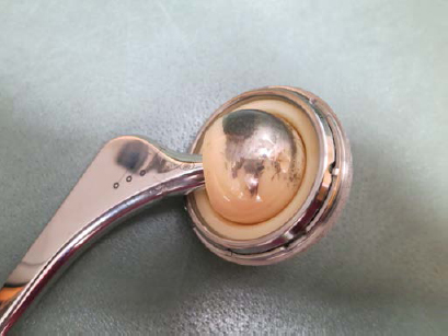
Metal on Polyethylene
Advantages
1. Tried and tested articulation with widely published evidence-base
2. Cheap
3. Easy to manufacture
Disadvantages
1. Polyethylene induced osteolysis (manufacturing process encouraging cross-linking to combat this problem with polyethylene)
Ceramic on Ceramic
Advantages
1. High wear resistance – High Young’s modulus of elasticity (Alumina 380GPa); Hard; Wettability
2. Biocompatibility; Biostability
Disadvantages
1. Brittle – concerns regarding fracture but with improved manufacturing process (increased purity, density, improvement in size and distribution of grains, accurate Morse taper) fracture rate in region of 0.02%
2. Squeaking (high pitched audible sound during hip movements) – often asymptomatic; multifactorial including component malpositioning, edge loading, impingement, third-body particles
3. Striped wear – impingement of the partially distracted head on rim of socket during gait
*(2) & (3) also reported in Metal on Metal articulations
Metal on Metal
Advantages
1. High wear resistance – High Young’s modulus of elasticity (Cobalt Chromium 210GPa); Fracture toughness; Hard
2. Self-polish – surface scratches may be substantially polished out during subsequent activity
Disadvantages
1. Metal ions – uncertainty regarding long-term biologic effects therefore caution regarding teratogenicity
2. Metallosis, Aseptic Lymphocytic Vasculitis Associated Lesions (ALVAR), Pseudotumours – believed to be due to wear debris (smaller and higher in numbers relative to Metal on Polyethylene articulation) and hypersensitivity.
3. Run-in wear – initial transitional elevation of wear which stabilises
Walter WL, Yeung E, Esposito C. A review of squeaking hips. J Am Acad Orthop Surg. 2010; 18(6): 319-26
Haddad FS, Thakrar RR, Hart AJ, Skinner JA, Nargol AV, Nolan JF, Gill HS, Murray DW, Blom AW, Case CP. Metal-on-metal bearings: the evidence so far. J Bone Joint Surg Br. 2011;93(5):572-9
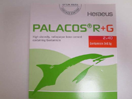
Clinical picture of bone cement.properties and factors affecting it
Properties
1. Acts as a space filling grout aiding load transfer
2. Viscoelastic – strong in compression, weak in shear
3. Young’s modulus of elasticity – 2.2GPa
Components
1. Monomer (liquid) – methylmethacrylate, toludene (accelerator) and hydroquinone (inhibitor)
2. Polymer (powder) – polymethylmethacrelate (PMMA), benzoyl peroxide (initiator), barium dioxide (radio-opacifier); chlorophyll (colouring agent)
1. Vaccum mix
2. Pulse lavage and brushing
3. Centraliser
4. Retrograde insertion with use of vent
5. Pressurisation
Polymerisation – exothermic reaction
1. Dough time –time from beginning of mixing to when cement is no longer sticking (2-3 min)
2. Setting time – time from beginning of mixing to point where surface temperature is half maximum (8-12 min)
3. Working time – Difference between dough time and setting time
Variables affecting polymerisation times
1. Environmental temperature – increase in temperature shortens dough and setting times
2. Humidity – increase in humidity increases setting time
3. Mixing technique – increase in frequency of beating and duration of mixing shortens dough and setting times
Variables affecting mechanical properties of cement
Beyond control of surgeon
1. Environmental temperature – increase in temperature decreases compressive strength
2. Equilibirum moisture content – cement absorption of fluid over time reduces strength
3. Strain Rate – stronger at high strain rates (viscoelastic)
1. Radio-opaque fillers – reduces strength by upto 5%
2. Antibiotics – up to 1 gram of antibiotic to 40 grams of polymer leads to no more than 4% reduction in strength; thorough mixing to avoid localised areas of weakness.
3. Mixing technique – frequency of beating and duration of mixing govern monomer loss from evaporation and porosity
4. Cement insertion – laminations harder to obliterate with increasing viscosity; pressurisation to reduce lamination and porosity
Partially under control of surgeon
1. Blood and tissue debris – reduces strength in unpredictable manner
2. Local stress risers secondary to implant design – cement is brittle
3. Constraint – viscoelastic nature of cement (creep) may be significant in unconstrained models
4. Cement mantle thickness – optimum thickness not known; ‘French paradox’
Complications
1. Hypotension
2. Fat embolism
3. Thermal necrosis of bone
4. Third body wear from retained loose fragments
5. Cement mantle defect
Lee AJ, Ling RS, Vangala SS. Some clinically relevant variables affecting the mechanical behaviour of bone cement. Arch Orthop Trauma Surg. 1978;92(1):1-18
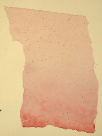
Clinical picture of bone graft
Definition – material that assists with bone healing through its osteoconductive, osteoinductive and/or osteogenic properties.
Properties
1. Osteoconduction – process by which graft acts as three dimensional scaffold for ingrowth of capillaries and osteoprogenitor cells from recipient host bed. Examples – Calcium phosphate, Synthetic polymers.
2. Osteoinduction – process supporting differentiation of mesenchymal stem cells into osteoprogenitor cells capable of forming new bone. Examples – Bone Morphogenetic Proteins (BMP), Transforming growth factor-β, Platelet-derived growth factor.
3. Osteogenic – use of naturally occurring materials that induce or support formation of bone. Examples – autologous bone marrow graft, autologous/allogenic bone grafts
Classification
Type
1. Cortical- structural integrity
2. Cancellous- more porous compared to cortical therefore more rapid revascularisation
3. Corticocancellous
Vascularity
2. Non-vascularised graft
Source
1. Autograft – same person
2. Allograft – same species (Isograft – twins)
3. Xenograft – different species
4. Synthetic
Preservation
1. Fresh – unprocessed; immunogenic
2. Fresh frozen – unprocessed stored at -70°C for minimum of 180 days; least impact on strength and preservation of immunogenicity and growth factors
3. Freeze dried – processed to remove soft tissues and washed to deplete cell and marrow content followed by freeze drying; least immunogenic but lowest likelihood of disease transmission as irradiated
Screening
Syphilis Ab
HBsAg
Anti-HCV
Anti-HIV
Anti-HBc
HCV-PCR
HIV-PCR
HBV-PCR
Einhorn TA. Enhancement of fracture-healing. J Bone Joint Surg Am. 1995; 77(6):940-56
http://www.nhsbt.nhs.uk/tissueservices/index.asp
4. Bone scintigraphy. Shown an image of bone scan. Asked about mechanism and uses
Nuclear medicine imaging that detects distribution of an injected radio-labelled tracer on image projections sensitive to gamma ray emissions. The process involves injection of a radio-labelled tracer followed by gamma camera recording of photoemissions.
Radiolabelled tracers
1. Technetium- 99m – affinity for osteoblasts; t1/2 6 hours
2. Gallium-67 – affinity for inflammatory proteins; t1/2 3.2 days
3. Indium-111 – autologous leucocytes obtained and labelled with Indium-111 then re-injected; t1/2 2.8 days
Triple phase bone scintigraphy
1. Nuclear angiogram (flow phase) – images immediately post-injection; demonstrates arterial flow and areas of hyperperfusion
2. Blood pool phase – images 5 minutes post-injection; demonstrates relative vascularity where areas of inflammation result in ‘pooling’ of blood due to stagnant flow in dilated capillaries (soft tissues and bone)
3. Static phase – images 3 hours post-injection; demonstrates bone activity
Limitations
1. High sensitivity but low specificity for increased bone activity
2. Two dimensional imaging – poor localisation of small lesions; alternative is single photon emission computer tomography (SPECT) imaging
Indications
1. Metastatic disease
2. Primary bone tumours
3. Trauma – stress fractures, occult fractures
4. Infection
5. Arthritis
6. Complex Regional Pain Syndrome
Hsu W, Hearty TM. Radionuclide imaging in the diagnosis and management of orthopaedic disease. J Am Acad Orthop Surg. 2012;20(3):151-9
Talk about calcium metabolism. What is rickets?
Calcium (plasma concentration 2.2 – 2.6mmol/L)
- 99% of body calcium stored in bone
- <1% in plasma: bound to albumin or free
Hypercalcaemia
Presentation
‘Bones, stones, groans and moans’
Causes
- Malignancy
- Hyperparathryoidism
Hypocalcaemia
Presentation
Neuromuscular irritability (Trosseau’s sign, Chvostek’s sign)
Causes
- Hypoparathyroidism
- Thyroidectomy
Vitamin D
Sources:
Minor – Dietary (eggs, liver, fish) Vitamin D absorbed in jejunum (Vitamin D deficiency – malabsorption syndromes)
Pathway:
1. Hydroxylation in liver – Vitamin D to 25-hydroxycholecalciferol (Vitamin D deficiency – cirrhosis)
2. Further hydroxylation in kidneys – 25-hydroxycholecalciferol to 1,25-dihydroxycholecalciferol and 24,25-dihydroxycholecalciferol (Vitamin D deficiency – chronic renal failure)
Actions:
1,25-dihydroxycholecalciferol (active metabolite)
- Increase calcium and phosphate absorption from gastrointestinal tract
- Increase osteoclastic resorption of bone
Enhances secretion – Increased parathyroid hormone (PTH) levels
Inhibits secretion – Decreased PTH levels, increased serum calcium and/or phosphate levels
Effect:
- Increase in serum calcium levels
- Increase in serum phosphate levels
Parathyroid hormone (PTH)
Source:
Chief cells of parathyroid glands
- Enhances secretion – decreased serum calcium and/or phosphate
- Inhibits secretion – increased serum calcium or 1,25-dihydroxycholecalciferol
Actions:
- Increases renal hydroxylation of 25-hydroxycholecalciferol
- Increases resorption of calcium and decreases resorption of phosphate in kidneys
- Increases osteoclastic resorption of bone
Effect:
- Increase in serum calcium levels
- Decrease in serum phosphate levels
Calcitonin
Souce:
Parafollicular C cells of thyroid gland
- Enhances secretion – increased serum calcium levels
- Inhibits secretion – decreased serum calcium levels
Actions:
- Decreases calcium absorption from gastrointestinal tract
- Decreases calcium resorption in kidneys
- Decreases osteoclastic resorption of bone
Effect:
Pathology
Vitamin D-dependent rickets/Osteomalacia
Vitamin D-resistent rickets (X-linked dominant hypophosphatemic rickets)
Hyperparathyroidism
Hypoparathyroidism
Renal osteodystrophy
Articular cartilage
- Aneural; Avascular; Alymphatic
- Cells embedded in extra-cellular matrix’
Composition
- Chondrocytes (up to 5% articular cartilage volume) – synthesis of matrix components and regulates matrix metabolism
- Water (65 – 80%) – provides nutrition and medium for lubrication; assists with load dependent deformation of cartilage
- Type II collagen (10-20%) – provides tensile strength to cartilage
- Proteoglycans (PG)
- Maintain fluid and electrolyte balance in articular cartilage – effect of negatively charged sulphate and carboxyl groups
- Large aggregating PG monomers e.g. aggrecans; small PGs e.g. decorin, fibromodulin
- Subunits of glycosaminoglycans (chondroitin sulphate, keratin sulphate) bound to central hyaluronic acid chain via link protein
- Maintain fluid and electrolyte balance in articular cartilage – effect of negatively charged sulphate and carboxyl groups
Structure
1. Superficial zone – thinnest; collagen fibres parallel to articular surface (tensile and shear strength); high water content; low PG content
2. Transitional zone
3. Deep zone – collagen fibres perpendicular to articular surface (resist compression); low water content; high PG content TIDEMARK – histologically visible border between deep zone and calcified zone
4. Calcified zone – low metabolic activity; Type X collagen
Cartilage healing
- Ability for cartilage defects to heal based on whether injury is deep to tidemark – i.e. involves subchondral vascular bone marrow resulting in release of mesenchymal progenitor cells into defect
- Fibrocartilage healing – biomechanically and structurally inferior to hyaline cartilage
Factors associated with cartilage repair
- Depth of defect
- Chondral – partial thickness; full thickness (down to subchondral bone)
- Osteochondral
- Chondral – partial thickness; full thickness (down to subchondral bone)
- Size of defect – smaller defects are less likely to affect stress distribution on the subchondral bone
- Age – mitotic and synthetic activity decreases with age
- Trauma
- Mechanical alignment – abnormal loading leading to excessive focal stresses and early degenerative disease
Surgical options for cartilage defects
Microfracture
Multiple controlled ‘microfractures’ to ensure release of mesenchymal progenitor cells from subchondral vasculature.
Steadman JR, Briggs KK, Rodrigo JJ, Kocher MS, Gill TJ, Rodkey WG. Outcomes of microfracture for traumatic chondral defects of the knee: average 11-year follow-up. Arthroscopy 2003;19(5):477-84
Mosaicplasty
Multiple cylindrical osteochondral plugs harvested from non-weightbearing area and plugged into prepared chondral defects to create a ‘mosaic’ pattern.
Hangody L, Vásárhelyi G, Hangody LR, Sükösd Z, Tibay G, Bartha L, Bodó G. Autologous osteochondral grafting – technique and long-term results. Injury. 2008;39 Suppl 1:S32-9
Autologous chondrocyte implantation (ACI)
Two stage procedure in which cartilage is harvested arthroscopically and grown in vitro, followed by implantation of chondrocytes into cartilage defect with an open procedure.
Peterson L, Vasiliadis HS, Brittberg M, Lindahl A. Autologous chondrocyte implantation: a long-term follow-up. Am J Sports Med. 2010;38(6):1117-24
7. DESCRIBE GAIT. Shown video of gait analysis. Methods of gait analysis
Gait cycle – events occurring when one foot makes contact with the walking surface and ends when the same foot makes contact again
Step length – linear distance between one heel strike to heel strike of other foot
Stride length – linear distance between one heel strike to next heel strike of same foot; Stride length = 2 x step length
Stance phase (60%)
1. Initial contact
2. Loading response
3. Mid-stance
4. Terminal stance
5. Pre-swing
Swing phase (40%)
1. Initial swing
2. Mid-swing
3. Terminal swing
*Double stance – 10% of gait cycle
Perry J. Gait analysis: normal and pathological function. Thorofare (NJ): SLACK; 1992.
Gage – Pre-requisites of gait based on Perry’s work
1. Stability in stance – stable when extremity weight-bearing on ground
2. Clearance in swing
3. Adequate step length – aids with efficiency of gait
4. Foot clearance in swing
5. Energy conservation (Gage) – ambulation must be energy efficient to ensure gait is functional
Gage JR: The treatment of gait problems in cerebral palsy.London, Mac Keith Press; 2004.
Saunders – Determinants of normal walking
1. Pelvic tilt
2. Pelvic rotation
3. Pelvic lateral displacement
4. Knee mechanisms
5. Knee flexion in stance phase
6. Foot and ankle mechanisms
Loss or compromise of two or more determinants produces uncompensated and inefficient gait.
Saunders JBDM, Inman VT, Eberhart HD: The major determinants in normal and pathological gait. J Bone JointSurg. Am 1953, 35A:543-728.
Perry – ‘3 Rockers’
1st rocker (heel rocker) – controlled plantarflexion to lower foot to walking surface during loading response.
2nd rocker (ankle rocker) – controlled tibial advancement and increasing dorsiflexion between mid and late stance during which the body advances over stationary foot.
3rd rocker (toe rocker) – propulsion with rapid ankle plantarflexion during pre-swing.
Perry J. Kinesiology of lower extremity bracing. Clin Orthop Relat Res 1974;102:18e31.
1. Clinical assessment including video analysis
2. Instrumented Gait Analysis (IGA) – Sagittal; Coronal; Transverse
3. Dynamic electromyography (D-EMG)
4. Plantar pressure analysis
Cerebral Palsy
Stiff knee gait
- Throughout gait cycle – knee held in extension
Jump knee gait
- Initial contact – increase hip and knee flexion with slight dorsiflexion
- Loading response and mid-stance – rapid knee extension and ankle plantarflexion
Crouch gait
- Throughout gait cycle – increase hip and knee flexion with excessive dorsiflexion
True equinus
- Calf spasticity or fixed ankle equinus contracture
Apparent equinus
- Increased hip and knee flexion throughout stance phase with relatively normal ankle motion
- Initial contact is with forefoot as a result of the flexed hip and knee
Cuccurullo S, editor. Physical Medicine and Rehabilitation Board Review. New York: Demos Medical Publishing; 2004. Gait Analysis. Available from: http://www.ncbi.nlm.nih.gov/books/NBK27235/
Chambers HG, Sutherland DH. A practical guide to gait analysis. J Am Acad Orthop Surg. 2002;10(3):222-31
Chang FM, Rhodes JT, Flynn KM, Carollo JJ. The role of gait analysis in treating gait abnormalities in cerebral palsy. Orthop Clin North Am. 2010;41(4):489-506
Shown clinical picture of diathermy
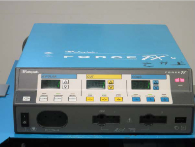
Diathermy (Greek diathrough;therme:heat) – cutting and coagulation of body tissue with a high frequency current
- High frequency alternating current
- Current between two electrodes in contact with the body heats all tissues between them
- Cutting mode – continuous current; Coagulation mode – pulsed current (50 – 100 s-1)
Monopolar diathermy
- Current established between active electrode (diathermy instrument) and Indifferent electrode (electrical plate/pad)
- Heating effect inversely proportional to area of contact with electrodes
- Active electrode small – heating concentrated at diathermy instrument
- Indifferent electrode large – minimal heating effect
- Active electrode small – heating concentrated at diathermy instrument
Bipolar diathermy
Risks
Implantable cardioverter defibrillators (ICDs)/Pacemakers
- Risk of electrical interference leading to inhibition of pacemaker output, temporary increase in pacing or loss of programme settings
- ICD pre-cautions when using diathermy
- Programme to ‘monitor only mode
- Magnet over ICD
- Deactivate (use of external defibrillator)
- Post-operative ICD check
- Programme to ‘monitor only mode
- Favour bipolar mode but if monopolar mode is used:
- Use in short bursts
- Ensure current pathway remote from ICD (importance of position of return electrode)
- Use in short bursts
MHRA. Guidelines for implantable cardioverter defibrillators (ICDs) – pacemaker perioperative management. www.mhra.gov.uk
Burns
- Superficial – spirit based skin preparation.
- Indifferent electrode – application of electrode diminishing area of contact increases heating effect and may result in a burn. Most modern electrosurgical units have in-built monitors which will sound an alarm and cut the current in cases where the electrode is ineffective.
- Alternative pathway – current diverted from indifferent electrode and travels from patient to the ‘ground’. If point of contact between patient and grounded object (drip stand, metal parts of operating table) is small, sufficient current can be generated to cause a burn. Use of electrosurgical units which have little or no reference to ‘earth’ will reduce risk.
- Channelling – use of diathermy on areas with narrow pedicle (e.g. fingers/toes, penis) leading to ‘channelling’ of current down pedicle
Smoke plume – vapour containing particles released during electrosurgery on body tissue
- Chemical by-products; Carbonised tissue; Blood particles; Viral DNA particles; Infectious viruses and bacteria
- Use of smoke evacuators with ultra-low penetrating air filters and high filtration face masks
Explosion
- Anaesthetic gases
- Bowel gases
- Ignition of skin preparations
9. Given picture of a prosthesis.
What is orthosis? parts of BK prosthesis
Prosthesis
Externally applied device used to replace wholly, or in part, an absent or deficient limb segment.
Indications for Amputation
- Peripheral vascular disease
- Trauma
- Tumours
- Infection
- Congenital abnormalities
Pre-operative assessment
- Multi-disciplinary approach
- Case-by-case approach
- Amputation level
Components of Prosthesis
1. Socket- connection between residual limb and prosthesis. e.g. ischial tuberosity-bearing, patella tendon-bearing
2. Suspension – attachment of prosthesis to residual limb. e.g. bands/belts, sleeves, suction
3. Articulation – non-articulating (e.g. solid-ankle/cushioned heel) or articulating (e.g. stance-phase control or swing-phase control)
4. Shank – link between socket and terminal device to restore limb length
5. Terminal device – non-energy storing or energy storing
Externally device applied used to modify the structural and functional characteristics of the neuromuscular and skeletal system.
International Organisation for Standardisation (ISO)
Nomenclature established in 1989 and endorsed by the American Association of Orthopaedic Surgeons (AAOS) and International Society for Prosthetics and Orthotics (ISPO) in 1992.
Nomenclature
Upper Limb – Shoulder (S), Elbow (E), Wrist (W), Hand (H), Finger (F)
Lower Limb – Hip (H), Knee (K), Ankle (A), Foot (F)
Spine – Cervical (C), Thoracic (T), Lumbar (L), Sacro-iliac (S)
Indications
Upper Limb
- Trauma – tendon, nerve, joint injuries; burns
- Post-surgery
- Painful conditions – arthritis
- Deformities – neuromuscular problems
Static; Dynamic; Combined (Functional)
Lower Limb
Spinal
- Trauma – fractures
- Post-surgery
- Deformity
- Intervertebral disc pathology
Ground Reaction Ankle Foot Orthosis (GRAFO)
- Accentuates knee extension at mid-stance (Indications – weak quadriceps)
- Compensate for weak/absent gastrocnemius or soleus (Indications – weak plantarflexors)
Elements
- Full toe plate; Rigid ankle in neutral; Rigid anterior tibial shell
Principles
- Newton’s Third Law – For every action, there is an equal and opposite reaction
- Ground Reaction Force (GRF) – the ‘reaction’ to the sum of body weight and centre of mass acting downwards during stance
- Plantarflexion/knee extension (PF/KE) couple – in normal gait, GRF maintained in front of knee centre in mid-stance by plantarflexors slowing down momentum of forward momentum of tibia. An extension moment is created at the knee by the GRF.
- Disruption of PF/KE couple – weak plantaflexors (e.g. spastic diplegia) fails to control progression of tibia over planted foot during stance, leading to excessive dorsiflexion. GRF passes posterior to knee centre thereby creating a flexion moment.
- GRAFO normalises the plantarflexion moment and due to rigid ankle component, limits dorsiflexion. The torque generated at the ankle is transferred to the knee, resulting in increased extension. i.e. PF/KE couple is restored with GRAFO.
International Organization for Standardization. ISO 8549-1: Prosthetics and orthotics-vocabulary, Part 1: General terms for external limb prostheses and external orthoses. Geneva: International Organization for Standardization, 1989:1-6.
International Organization for Standardization. ISO 8549-3: Prosthetics and orthotics-Vocabulary, Part 3: Terms relating to external orthoses. Geneva: International Organization for Standardization, 1989:1-5.
Bowker JH, Michael JW (eds.) Atlas of Limb Prosthetics- Surgical, Prosthetic and Rehabilitation Principles. St. Louis: American Academy of Orthopaedic Surgeons and C.V. Mosby Co. :1992.
Magnetic resonance (MR) imaging employs a stationary magnetic field and application of an external radiofrequency pulse to create an image based on the response of hydrogen proton molecules in the studied tissue.
Mechanism
- Magnetic field results in parallel alignment of hydrogen protons within studied tissue(s)
- Radiofrequency pulse results in energy absorption by hydrogen protons leading to
- Change in direction and precession of protons
- Above changes dependent on direction of applied radiofrequency pulse with respect to stationary magnet
- Change in direction and precession of protons
- Cessation of radiofrequency pulse results in reverting of alignment of protons back to direction before radiofrequency pulse and loss of coherence of precession. There is a time-dependent release of energy from the protons that was previously absorbed.
- Electronic image produced based on capturing patterns of energy release from protons
Terminology
T1 (Spin-lattice or longitudinal relaxation time)
Related posts:

Stay updated, free articles. Join our Telegram channel

Full access? Get Clinical Tree


