As the population ages, more patients are developing degenerative changes of the spine and associated pain. Although interventional procedures for axial and radicular spine pain have been available for decades, common imaging modalities have relied on ionizing radiation for guidance. Over the past decade, ultrasound has become increasingly popular to image both peripheral musculoskeletal and axial structures. This article reviews the use of ultrasound in the guidance of spine procedures, including cervical and lumbar facet injections and medial branch blocks, third occipital nerve blocks, thoracic facet and costotransverse joint injections, sacroiliac joint injections, and caudal and interlaminar epidural injections.
Key points
- •
Ultrasound (US) has become a more common imaging modality for spinal interventions.
- •
US has some advantages and disadvantages compared with fluoroscopy and other imaging modalities.
- •
Most typical spinal pain procedures described under fluoroscopy have also been described with US guidance.
- •
Although there are multiple studies demonstrating the accuracy of US-guided spine procedures using cadaveric dissections as well as comparing their accuracy to procedures with CT or fluoroscopic guidance, there are no large studies comparing the safety or efficacy of US-guided spinal interventions to CT or fluoroscopic guidance.
- •
Some spinal interventions where the spinal vascular supply may be at risk may still benefit from fluoroscopic or CT-confirmed contrast-controlled verification.
Introduction
The aging population presents musculoskeletal clinicians with an increasing incidence of degenerative changes of the spine and associated pain. Although interventional spine procedures have been in use for decades, common imaging modalities have relied on ionizing radiation for guidance. US has more recently become used to image axial structures and guide procedures in this region.
Like other imaging modalities, US has certain advantages and disadvantages. US imaging is ideal for visualizing soft tissues, bony surfaces, and needle manipulation in real time. Significant nerves and blood vessels can readily be visualized by a well-trained sonographer. Unfortunately, the deeper the tissue, the more challenging sonographic visualization becomes. In addition, bone completely obstructs US visualization of deeper structures in the path of sound waves. As such, clinicians should consider US one of several options for image guidance for spine procedures.
Ultrasound-guided cervical spine procedures
Anatomy
The cervical spine is composed of 7 vertebral levels with the atlanto-occipital (C0-C1) and atlantoaxial (C1-C2) having unique anatomic features. This article’s focus is on the middle and lower cervical joints. Potential pain generators at each level include the vertebral body, facets, nerve roots, and disks. Under US guidance, the cervical facets and medial branches are relatively accessible in most patients. At the C2-C3 level, the facet may refer pain to the third occipital nerve (TON), which may also be blocked.
Indications
The cervical facets can be prominent pain generators in patients with both occipital and posterior neck pain. This pain can be related to osteoarthritic and whiplash injuries. Facetogenic pain may be present despite normal CT, bone scan, or MRI findings. In whiplash-induced neck pain, medial branch blocks of the cervical facets are often needed to confirm the correct pain generator. Common interventions for facetogenic pain in the cervical spine include facet injections, medial branch blocks, and radiofrequency ablation of the medial branches.
Technique
Ultrasound-guided technique for identification of the correct cervical level for cervical facet injections
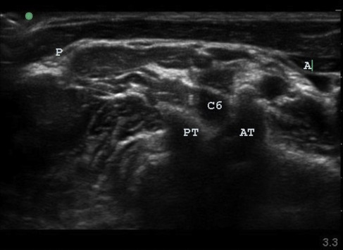
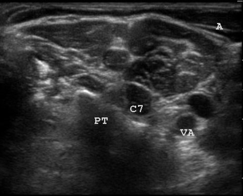
The patient is placed in the lateral decubitus position with the side of interest facing upward. Typically, a high-frequency (>10 MHz) linear-array transducer is used in the axial plane to scan the lateral neck starting caudally ( Fig. 1 ). The posterior tubercle of the segmental foramen can be well visualized. The C7 foramen can be localized because there is no prominent anterior tubercle ( Fig. 2 ). The other cervical foramina have prominent anterior tubercles. At the C6 foramen, the C5-C6 facet is visualized. The needle then is advanced in-plane using an anterior-to-posterior approach. A posterior approach using a low-frequency (<10 MHz) curvilinear-array transducer in the prone position has also been described.
Ultrasound-guided technique for cervical medial branch blocks and third occipital nerve blocks
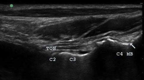
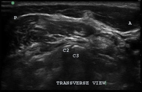
For a TON block, the patient is placed in the lateral decubitus position and the transducer is placed in the coronal plane with the cephalic end of the transducer on the mastoid process. Next the transducer is moved 5 mm to 8 mm posteriorly until the articular pillar of C2 is well visualized ( Fig. 3 ). The transducer is then translated caudally until the C2-C3 articulation along with the TON is visualized ( Fig. 4 ). To visualize the more caudal medial branches, the transducer can be translated caudally while maintaining a coronal view. The hyperechoic peaks with a cleft are articular processes and joints, whereas the hyperechoic valleys are where the medial branches lie. In an out-of-plane approach, a short 25-gauge needle can be advanced from anterior to posterior, targeting the deepest point in the near-contiguous hyperechoic bony ridge. Only 0.3 mL of a local anesthetic is needed under direct observation. The vertebral artery, radicular feeder arteries, nerve roots, and spinal cord are in close proximity to these structures, and clinicians should take appropriate precautions to carefully avoid them.
Ultrasound-guided thoracic procedures
Anatomy
The thoracic spine is composed of 12 vertebral levels. Thoracic back pain is not as common as lumbar or cervical pain; however, it is present in approximately 15% of adults. This pain can be chronic and severe. Common pain generators include the disks, facets, and nerve roots. Additional sources of pain, however, include the costovertebral and costotransverse joints. With US imaging alone, the disks and costovertebral joints are not commonly injected due to poor visualization. US-guided facet and costotransverse joint injections, however, have been described.
Indications
Thoracic joint injections are usually performed to treat inflamed, painful, arthritic facets and costotransverse joints. If conservative options fail, CT, bone scan, or MRI can be used to help localize the pain generator. Because of the close proximity of the disks and facet, costotransverse, and costovertebral joints to each other at each segment, it is frequently difficult to isolate the pain generator using physical examination alone.
Technique
Ultrasound-guided technique for thoracic facet injections
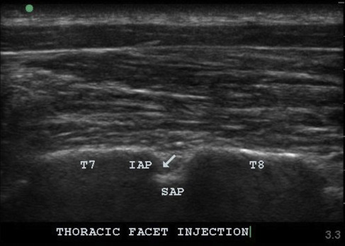
A key to completing successful thoracic facet injections is isolating the correct level. Caudal-to-cranial scanning is used to locate the 12th rib on the affected side. In the sagittal plane, the 12th rib is followed medially until the costotransverse joint is visualized. When translating the transducer slightly more medially, the hyperechoic lamina of the 12th vertebra becomes visible. The transducer is then moved in a cephalic direction while counting laminar levels until the level of choice has been located. At this point, while still in the sagittal plane, the transducer is tilted medially so the US beam is aiming slightly lateral ( Fig. 5 ). The sawtooth pattern of the facets then comes into view. At this point, the skin is marked to delineate the transducer location and needle entry site caudally. The needle is subsequently advanced in a caudal-to-cephalic fashion into the joint.
Ultrasound-guided technique for costotransverse joint injections
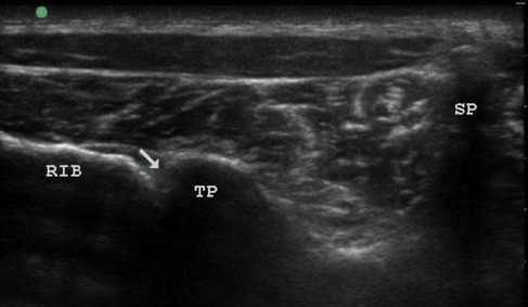
The patient is placed in the prone position. As described previously with the thoracic facets, caudal-to-cranial scanning in the sagittal plane is used to identify the 12th rib on the side of interest. The ribs can then be counted until the level of interest has been reached. The transducer is then rotated directly over until the rib and transducer are parallel. The rib is then followed medially until the costotransverse joint is visualized ( Fig. 6 ). The skin is marked to verify the position of the transducer. After the skin is prepped in the usual sterile fashion, a 22-gauge spinal needle is advanced in-plane in a lateral-to-medial approach into the joint.
Ultrasound-guided lumbar spine procedures
Lumbar pain and radicular leg pain are leading reasons people seek treatment with their primary care provider. Typical treatment options include physical therapy, oral analgesic/anti-inflammatory medications, and injection therapies. Recently, image-guided interventions have become common among pain specialists. Over the past decade, more evidence is building that US is a viable imaging modality for lumbar spinal procedures.
Anatomy
The lumbar spine is composed of 5 vertebral levels separated by disks anteriorly. These disks can become a source of pain, or they can compress adjacent nerve roots causing neuropathic pain. Posteriorly, the lumbar facet joints are composed of the inferior articular process of the more cephalic level and the superior articular process (SAP) of the more caudal level. These facet joints are diarthrodial, containing hyaline cartilage and a synovial lining.
Indications
With arthritic changes or inflammation, the facets can be a significant pain generator. Skeletal imaging, such as MRI, plain x-ray films, or CT scan, is needed to confirm the number of lumbar vertebrae prior to any US-guided lumbar intervention, because anatomic anomalies can affect procedural performance and safety.
Technique
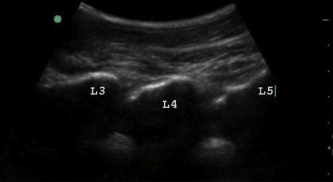
Ultrasound-guided technique for identification of the correct lumbar level for lumbar facet injections and medial branch blocks
The patient is placed in the prone position with either 1 or 2 pillows under the lower abdomen to flex the lumbar spine for optimal visualization. Usually, a low-frequency (<10-MHz) curvilinear-array transducer is used to obtain sufficient sonographic penetration. The transducer is placed over the midline in a sagittal plane at the lumbosacral junction to visualize the lumbar spinous processes and the crest of S1. The lumbar spinous processes can be counted and labeled on the skin. The transducer can then be translated laterally, maintaining a strict sagittal view until a contiguous sawtooth pattern is observed ( Fig. 7 ). This long-axis view of the spine shows a series of more superficial rounded hyperechoic facets in series ( Fig. 8 ). Just lateral to the facets and parallel to the spine in a slightly deeper plane, the medial transverse processes (TPs) come into view ( Fig. 9 ).