Tibial Shaft Fractures: Taylor Spatial Frame
Charles J. Taylor
INDICATIONS AND CONTRAINDICATIONS
Tibial shaft fractures are serious injuries and are most commonly seen in adult and adolescent patients. Because of its subcutaneous location anteriorly and medially, trauma to this area leads to a high percentage of open fractures when compared to the femur or upper extremity. Even with closed fractures, severe soft-tissue injury may be present, which may complicate treatment. Swelling, fracture blisters, and even full-thickness skin loss may often occur with high-energy displaced fractures. Compartment syndrome can occur following both closed and open tibial fractures. In addition to injuries caused by direct trauma, many fractures occur as the result of torsional and bending forces. This most commonly occurs in the distal third of the tibia near the metadiaphyseal junction.
Strong indications for treatment of a tibial fracture with a computer-assisted external fixation frame include (a) open fractures with bone loss, (b) tibial shaft fractures with epimetaphyseal extension, (c) fractures with significant loss of reduction (>3 weeks) following cast or brace treatment, and (d) infected fractures. Relative indications for this technique include (a) selected complex open fractures, (b) unstable closed fractures with significant soft-tissue compromise, and (c) some tibial fractures with a compartment syndrome following fasciotomy. Although not specifically addressed in this chapter, delayed union, nonunion, and malunion of many tibial fractures can be treated with the computer-assisted external fixation.
Historically, external fixation was reserved for patients with severe open fractures. Results from the last 10 to 20 years demonstrate the efficacy and safety of external fixation for fractures that may also be treated with intramedullary nails. There are no absolute contraindications for its use as a primary method of treating acute shaft fractures.
PREOPERATIVE PLANNING
History and Physical Exam
The severity of a tibial fracture can be distracting, but a thorough history must be obtained and a complete physical exam performed. The patient’s general medical history should identify allergies to medicine, current medications, current medical conditions being treated, and previous surgeries. The social situation, especially support at home, may be important for patients in external fixation.
The specific mechanism of injury should be sought from the patient, witnesses, and first responders to understand the energy involved, appreciate direct soft-tissue injury, and alert the medical team to other possible injuries remote to the obvious tibial fracture. Significant bleeding at the accident scene or during transport suggests an arterial injury as well. Fractures sustained from crushing injuries, during tornados, and in association with electrical injuries alert the surgeon to the possible need for subsequent débridements and soft-tissue procedures.
Patients with tibial fractures present in a variety of settings from level 1 trauma centers to outpatient offices. The multiply injured patient, especially if unconscious, must be examined thoroughly and repeatedly. The c-spine should be immobilized and the obvious extremity fractures splinted and wounds dressed. The patient should be carefully log-rolled until the spine is cleared.
Repeated neurologic and vascular assessments of the extremity should be made to identify a more proximal injury or compartment syndrome. In the conscious patient, increasing pain and decreasing sensation are the earliest signs and symptoms of compartment syndrome. The limb must be inspected for local tenderness, ecchymosis, abrasions, fracture blisters, and open wounds. The knee and ankle joints are evaluated for tenderness, swelling, stability, and range of motion if possible. A well-padded long-leg splint is applied following gentle longitudinal traction to grossly realign the fracture.
Imaging Studies
Full-length anteroposterior (AP) and lateral radiographs of the tibia and fibula must be obtained. These radiographs should include both views of the knee and ankle. Tall patients may require overlapping radiographs. If there is fracture extension into the knee or ankle joints, or the physical examination suggests articular involvement, a CT scan can be obtained to help delineate the fracture morphology and plan treatment.
Timing of Surgery
Considering the wide spectrum of presentations of tibial fractures, surgical timing varies greatly from emergent to “elective.” In the multiply injured trauma center patient, surgical treatment of the tibia may follow more urgent surgical treatments by general surgery and neurosurgery. Patients with open fractures should receive therapeutic doses of Ancef and Tobramycin for 48 hours. Anaerobic coverage is considered for gross contamination, and tetanus prophylaxis is given if appropriate. Open fractures should undergo débridement, irrigation, and stabilization within a few hours of the injury when possible. Likewise, fractures with compartment syndrome are addressed emergently with fasciotomy and stabilization.
Closed unstable low energy fractures may be splinted and seen in close follow up in an outpatient clinic. Instructions should be given for ice, elevation, and signs of compartment syndrome. The patient should be non-weight bearing on the injured extremity.
Patients with higher energy fractures, especially with crushing can be admitted for more careful monitoring prior to urgent surgery.
Surgical Tactic
The Taylor Spatial Frame may be used in two modes, acute reduction or gradual reduction. In the simplest mode, after fracture fragments are fixed, the frame can be acutely manipulated to reduce the fracture under direct vision for Grade III open fractures or C-arm control for closed and Grades I and II open fractures. The frame is then locked in position. No computer is necessary for this type of acute reduction. In its most versatile mode, the frame may be gradually adjusted to reduce the fracture. This reduction is done gradually over the first few weeks. Additional anesthesia is not necessary. This gradual reduction can be used for the entire reduction process or after an initial acute reduction.
Prior to surgery, it is helpful to “size” the leg for ring diameter and to anticipate the number and approximate placement of half pins and wires. Also, plan the approximate position and plane of steerage pins for oblique fractures. A full-sized sketch or wax pencil markings of standard radiographs are helpful.
INTRODUCTION TO THE TAYLOR SPATIAL FRAME
The Taylor Spatial Frame fixator consists of two rings or partial rings connected by six telescopic struts with special universal joints (Fig. 30.1). By adjusting only strut lengths, one ring can be repositioned with respect to the other. Special FastFx struts have two modes of adjustment. In the unlocked position, they are free to slide like a piston for an initial reduction in surgery (Fig. 30.2). In the locked mode, the struts may be gradually adjusted allowing further reduction of the residual skeletal deformity in the clinic or patient’s home (Fig. 30.3). The Spatial Frame fixator is capable of correcting all six axes of the deformity, three translations, two angulations, and rotation by adjusting lengths of struts only.
The ability to make gradual adjustments to the frame after the surgical application allows the surgeon to separate fracture fixation from reduction and even delay reduction for weeks. The surgeon should concentrate on stable fixation of the major fragments during surgery. After stable fixation, the fragments can be further acutely reduced with the fast fix struts in their unlocked position or gradually reduced in the locked position. This ability to achieve delayed near anatomic reductions is the greatest strength of the Taylor Spatial Frame technique.
Frames may be tapered by using rings of different sizes to make them less cumbersome and safer while descending stairs. Generally, one to two fingerbreadths clearance anterior between the ring and skin and two to three posteriorly are adequate (Fig. 30.4). A 2/3 ring open posterior is frequently used for proximal tibial fractures to allow full knee flexion. Complete and 2/3 rings range in size from 80 to 300-mm internal diameter in 25-mm increments. Accessory rings and partial rings may be attached to extend the levels of fixation (Fig. 30.5). Standard and short foot plates are available in 155- and 180-mm internal diameters. “U-Plates” are also used for foot fixation (Fig. 30.6).
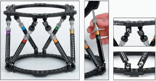 FIGURE 30.1 One Spatial Frame ring can be repositioned with respect to the other by adjusting strut lengths. (©J. Charles Taylor.) |
The assembly drawing is shown in Figure 30.7. The open area of a 2/3 ring can be positioned based on surgeon’s choice. Six identifier clips, uniquely colored and numbered 1 through 6, are provided with each frame. Each numbered/colored clip is applied to a strut beginning with strut 1 (which is attached to a tab directly anterior on the proximal ring) and progressing counterclockwise as viewed from the proximal end of the frame.
Hybrid frames may be used with ring to bar connectors to extend levels of fixation, especially with half pins. Hex-Fix (trademark) and Jet-X (trademark) and other rod and rail fixators are designed for use with ring fixators and are useful accessories and attachments to provide lower profile half pin fixation beyond the rings.
Adequate Fixation
The author strongly recommends predrilling for half pins and does not use self-drilling pins. Threaded titanium half pins and/or tensioned 1.8-mm-diameter stainless steel wires are used with the Spatial Frame. To minimize the number of pins and wires, their placement should be optimized to provide the greatest stability within anatomic constraints. The entire length of the anterior/medial tibia is available for half-pin fixation. Four and 5-mm titanium half pins are used for adolescents and small adults. Usually, 5-mm half pins are used in larger patients. Long fragments are fixed with at least two and often three half pins in different planes. Pins should be spread longitudinally along a significant portion of each fragment trying to stay out of the zone of soft-tissue injury (Fig. 30.8). Obviously, this is not always possible. Shorter periarticular fragments are fixed with at least two multiplanar half pins at approximately 70 degrees to each other. Adding a single olive wire in the coronal plane adds significantly to the stability of a short fragment. Alternatively, three 1.8-mm olive wires can be used to stabilize a short proximal or distal fragment (Fig. 30.9). The crossing angle of these wires must be optimized within anatomic limits. Two “olives” should block the fragment from each side, and a third olive wire should block the fracture obliquity. Stability for a very short proximal tibial fragment can be increased by transfixing the tibia and fibula at the level of the fibular head with a tensioned wire. For very short distal tibial fragments, transosseous wires can traverse the syndesmotic region. Intermediate length fragments may be fixed with a combination of wires and half pins.
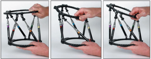 FIGURE 30.2 A Spatial Frame may be acutely adjusted by hand with all struts in the unlocked position. (© J. Charles Taylor.) |
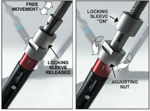 FIGURE 30.3 Fast Fx struts are free to slide in the unlocked position for acute fracture reduction. The locking sleeve is advanced to lock the strut. The locked strut can still be gradually adjusted by rotating the nosepiece. (© J. Charles Taylor.) |
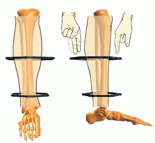 FIGURE 30.4 Spatial Frames may be tapered and eccentric. Allow sufficient soft-tissue clearance to prevent frame impingement. (© J. Charles Taylor.) |
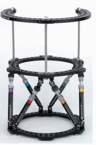 FIGURE 30.5 A tapered frame consisting of a 180-mm-diameter 2/3 ring proximally connected to a 155-mm Spatial Frame distally with Ilizarov threaded rods. The proximal 2/3 ring with the opening posteriorly allows full knee flexion. (© J. Charles Taylor.) |
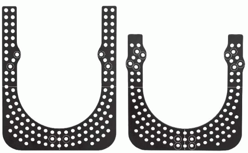 FIGURE 30.6 Additional skeletal stability and prevention of equinus deformity may be gained by fixing the foot to a foot plate or U-plate. (© J. Charles Taylor.) |
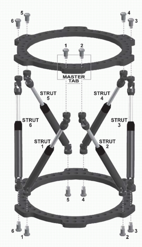 FIGURE 30.7 Each numbered/colored clip is applied to a strut beginning with strut 1 (which is attached to the designated Master Tab anteriorly) and progressing counterclockwise as viewed from the proximal end of the frame. The computer program assumes that the universal joints connecting strut 1 and strut 2 to the proximal ring are aligned directly anterior with respect to the reference fragment. Different rotational alignments, especially for more proximal femoral and humeral applications, can be accommodated by changing rotary frame offset. (© J. Charles Taylor.) |
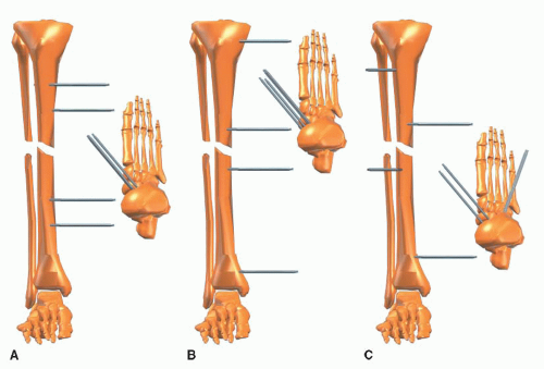 FIGURE 30.8 A. Do not limit mechanical stability by two sets of parallel pins. (© J. Charles Taylor.) B. Fracture stability is significantly improved by extending the working length in each fragment. C. Stability is further increased by inserting pins in different planes, achieving multiplanar fixation. (© J. Charles Taylor.) |
The foot may be included temporarily for additional fracture stability, soft-tissue immobilization, and prevention of equinus contracture. A distal shaft fracture with significant soft-tissue injury as well as in patients with peripheral nerve injuries or head trauma should have the fixation extended to the foot in the beginning (Fig. 30.10). The foot plate is attached to the distal ring of the Spatial Frame with threaded rods. Usually, a combination of olive wires and half pins are placed in the calcaneus and two wires in the metatarsals (Fig. 30.11). Shorter frames may be constructed with short body struts. Tapered and open section frames may be applied. Segmental fractures are usually treated with a ring or 2/3 ring for each major fragment (Fig. 30.12A-C).
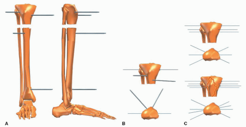 FIGURE 30.9 A. Short periarticular fragments can be stabilized with two to three multiplanar half pins. B. Stability is improved significantly by at least one tensioned wire. C. Good stability is provided by three multiplanar tensioned wires for short extra-articular fragments. Four multiplanar wires are used for intra-articular fractures such as a bicondylar tibial plateau fracture. (© J. Charles Taylor.) |
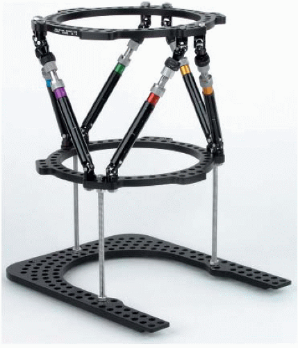 FIGURE 30.10 The accessory foot plate or U-Plate is attached to the Spatial Frame with threaded rods. (© J. Charles Taylor.) |
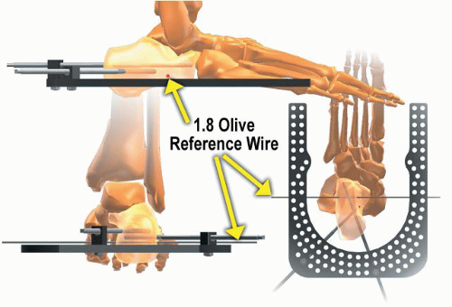 FIGURE 30.11 Angled wires and/or pins are used in the calcaneus. Usually, two wires are used in the forefoot (not shown) at the level of the metatarsal necks. (© J. Charles Taylor.) |
Steerage Pin
Oblique fracture stability can be improved by using steerage pins on either side of the fracture (1). These pins should be angled 15 to 20 degrees from the transverse plane along the plane of the fracture (Fig. 30.13). These pins will cause dynamic interfragmentary compression with weight bearing and minimize fracture shear. It is still beneficial if only one steerage pin is used.
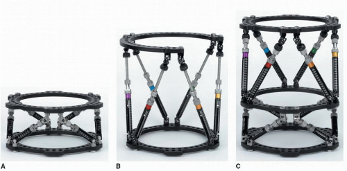 FIGURE 30.12 A. Shorter struts allow more stable fixation when indicated. Accessory rings could be added to extend the level of fixation. B. The component system permits custom frames such as this tapered open section frame for distal femoral application. C. Each ring has six tabs and can serve as the intermediate ring for a segmental application. Spatial Frames come preassembled or can be assembled from components. (© J. Charles Taylor.) |
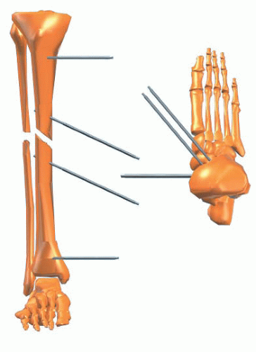 FIGURE 30.13 Steerage pins are angled 15 to 20 degrees approximating the major oblique fracture plane. They are placed on each side of the fracture and are used with other pins and/or wires. Steerage pins increase interfragmentary compression and reduce shear at the fracture site during ambulation. (© J. Charles Taylor.) |
SURGERY
Positioning
General, spinal, or continuous epidural anesthetics may be used as indicated. Care must be taken when using spinal or regional anesthesia to avoid masking a postoperative compartment syndrome. The patient is positioned supine on a padded radiolucent table top. Whenever possible, tables that have no metal rails improve visualization of the fracture with the image intensifier.
Imaging
The C-arm is positioned on the opposite side of the injury. The image monitor is usually best positioned at the foot of the table.
Skin Prep and Drape
A tourniquet is placed on the proximal thigh, but is generally used only for débridement of open fractures or in cases with substantial bleeding. The tourniquet should be deflated prior to pin and wire insertion. Longitudinal traction through a calcaneal pin or wire may be useful to improve overall alignment but is not routinely employed. A few folded towels are strategically placed to elevate leg segments as needed for frame application. The skin is prepped with a Betadine Scub followed by Betadine Prep. Alternatively, DuraPrep may be used.
Fixation/Pin and Wire Technique
Pin and wire location and insertion technique are some of the most important factors for patient tolerance, frame longevity, and minimizing additional surgery. Bayonet point wires with cutting relief are ideal for metaphyseal and especially diaphyseal bone (Fig. 30.14). Wires are inserted percutaneously to the near cortex, then slowly drilled across both cortices with frequent pauses to prevent overheating, and tapped through the far soft tissue. The wire is irrigated with saline for additional cooling. It is important to achieve bicortical purchase with wires and pins to enhance mechanical stability, decrease pin loosening, and minimize thermal necrosis. The small incision to insert the drill sleeve or release the skin for the olive is closed with a simple suture.
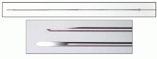 FIGURE 30.14 Olive wire with close-up of cutting tip. (© J. Charles Taylor.) |
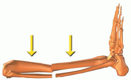 FIGURE 30.15 Determine the approximate position of one ring, usually on the shorter fragment, and mark the skin. Place a second mark 18 cm from the first for fast fix struts or 15 cm for standard struts. These marks are the approximate positions for the rings. (© J. Charles Taylor.) |
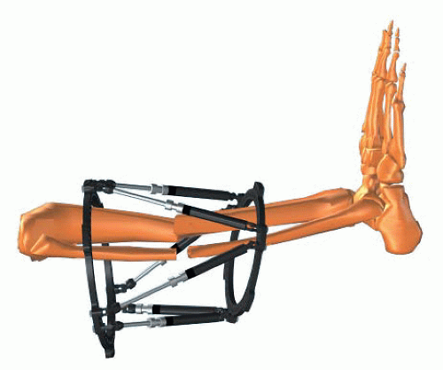 FIGURE 30.16 Slide the frame over the leg. (© J. Charles Taylor.) |
Frame Application
Assemble the Spatial Frame with two rings and six medium FastFx struts in their unlocked position (see Fig. 30.7). Choose the approximate level for one ring and mark the skin. Mark the skin 18 cm away for the position of the second ring (Fig. 30.15). Slide the frame onto the leg (Fig. 30.16). The frame does not have to be centered longitudinally over the fracture. Make a short longitudinal incision for a sagittal plane half pin. Using a five-hole Rancho Cube as a drill guide (Fig. 30.17), drill a pilot hole for the half pin. Insert the half pin (Fig. 30.18) and attach it to an appropriate length Rancho Cube maintaining the desired soft-tissue clearance (Fig. 30.19). Attach the Rancho Cube to the Spatial Ring using the inner tier of holes at the anterior position (Fig. 30.20) on the master tab, the junction of the number 1 and number 2 struts. Using as long a Rancho Cube as possible, insert a half pin in the anterior/medial plane off the proximal face of the proximal ring (Fig. 30.21). Using a Rancho Cube as a drill guide (Fig. 30.22), insert another half pin in the sagittal plane on the proximal portion of the distal fragment (Fig. 30.23). Attach the Rancho Cube to this pin maintaining the 1 to 2 fingerbreadths soft-tissue clearance (Fig. 30.24). Attach the Rancho Cube to the distal ring in the anterior hole (Fig. 30.25). Insert a second half pin in the distal fragment in the anterior medial plane using as long a half pin as possible (Fig. 30.26). Usually a third half pin is inserted in each fragment in a different plane and is attached to its respective ring with a one-or two-hole Rancho Cube (Fig. 30.27).
Stability can be increased on longer fragments by extending the spread of fixation with an accessory ring connected to one of the primary rings with threaded rods or posts (see Fig. 30.5) or with a hybrid frame extension using a ring to rod connector.
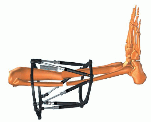 FIGURE 30.17 Lay a long Rancho cube along the tibial crest for a sagittal pin. (© J. Charles Taylor.) |
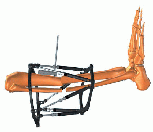 FIGURE 30.18 Using the cube as a drill sleeve guide, drill the appropriate pilot hole and insert a half pin by hand. (© J. Charles Taylor.) |
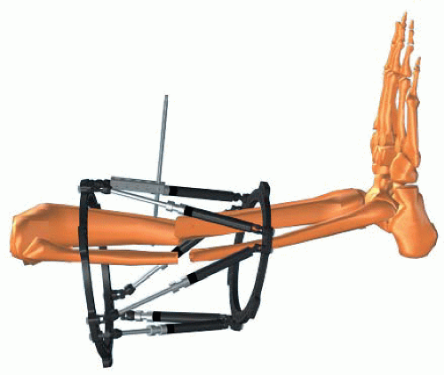 FIGURE 30.19 Slide the cube along the pin to adjust anterior/posterior soft-tissue clearance and tighten the pin to the cube with a set screw or short bolt. (© J. Charles Taylor.) |
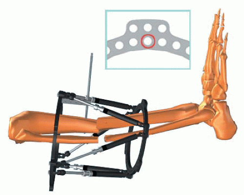 FIGURE 30.20 Attach the Rancho cube to the anterior hole of the ring using the inner tier of holes. See inset. (© J. Charles Taylor.) |
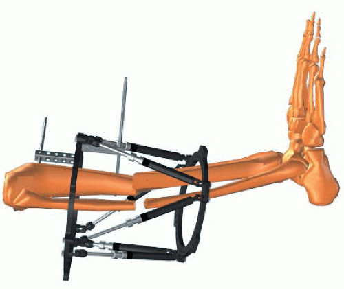 FIGURE 30.21 Insert a second half pin in the anterior medial plane using as long a Rancho cube as possible. (© J. Charles Taylor.) |
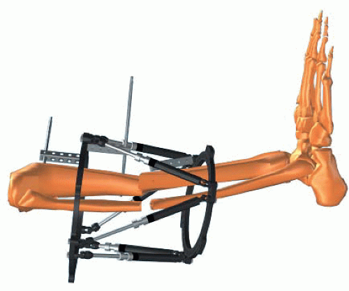 FIGURE 30.22 Lay a long Rancho cube along the tibial crest of the second fragment for a sagittal pin. (© J. Charles Taylor.) |
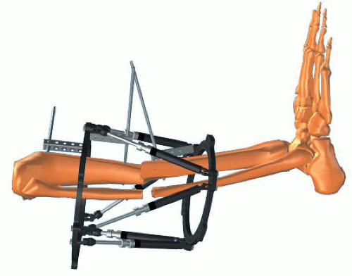 FIGURE 30.23 Using the cube as a drill sleeve guide, drill the appropriate pilot hole and insert a half pin by hand. (© J. Charles Taylor.) |
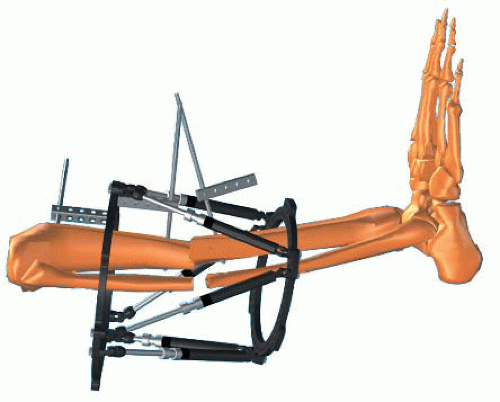 FIGURE 30.24 Slide the cube along the pin to adjust anterior/posterior soft-tissue clearance and tighten the pin to the cube with a set screw or short bolt. (© J. Charles Taylor.)
Related posts: Intra-Articular Fractures of the Distal Humerus: Total Elbow Arthroplasty
Humeral Shaft Fractures: Open Reduction Internal Fixation
Distal Humerus Fractures: Open Reduction Internal Fixation
Tarsometatarsal Lisfranc Injuries: Evaluation and Management
Ankle Fractures
Patella Fractures: Open Reduction Internal Fixation Intra-Articular Fractures of the Distal Humerus: Total Elbow Arthroplasty
Humeral Shaft Fractures: Open Reduction Internal Fixation
Distal Humerus Fractures: Open Reduction Internal Fixation
Tarsometatarsal Lisfranc Injuries: Evaluation and Management
Ankle Fractures
Patella Fractures: Open Reduction Internal Fixation
Stay updated, free articles. Join our Telegram channel
Full access? Get Clinical Tree
 Get Clinical Tree app for offline access

|