Tibial Shaft Fractures: Spatial Frame
J. Charles Taylor
Indications / Contraindications
Tibial shaft fractures are relatively common injuries in adults and adolescents. Because of its subcutaneous location and because it is frequently the site of direct injury, tibial fractures are open more often than other long bone fractures. Even in closed fractures, severe soft-tissue injury may be evident or initially suspected. Swelling, fracture blisters, and even subsequent full-thickness skin loss may complicate an initially closed fracture. Compartment syndrome may be present in open as well as closed fractures. In addition to injuries caused by direct trauma, the tibia and fibula may fracture as a result of torsional and bending forces. This usually occurs at the junction of the distal 1/4 tibia where there is the lowest section modulus.
Indications for treatment with Spatial Frame include (a) open fractures with bone loss, (b) fractures with compartment syndrome, (c) open fractures, (d) unstable closed fractures, and (e) fractures with subsequent loss of reduction following initial casting. Although not addressed specifically in this chapter, delayed union, nonunion, and malunion of the tibia can also be treated with the Spatial Frame.
Because external fixation historically has been reserved for the worst clinical situations, there is no contraindication for its use as the primary definitive method for acute shaft fractures.
Preoperative Planning
The initial exam should include a thorough inspection of the limb and complete neurovascular assessment, which must be repeated regularly to detect impending compartment syndrome. In the conscious patient, increasing pain and decreasing sensation are the earliest signs and symptoms of compartment syndrome. The limb must be inspected for open wounds and hemarthrosis of the knee or ankle. The entire lower extremity is then splinted in a well-padded, long, leg splint to achieve at least gross realignment of the fragments.
Proximal or distal shaft fractures may include extension into the joint. If the initial anteroposterior (AP) and lateral radiographs of the tibia and fibula from knee to ankle are suspicious but inconclusive for intra-articular extension, a computed tomography (CT) scan including the joint should be obtained to help aid diagnosis and treatment.
Proximal or distal shaft fractures may include extension into the joint. If the initial anteroposterior (AP) and lateral radiographs of the tibia and fibula from knee to ankle are suspicious but inconclusive for intra-articular extension, a computed tomography (CT) scan including the joint should be obtained to help aid diagnosis and treatment.
The Spatial Frame may be used in two modes, acute reduction or gradual reduction. In the simplest mode, after fracture fragments are fixed, the frame can be acutely manipulated to reduce the fracture under direct vision for open fractures and c-arm control for closed and open fractures. The frame is then locked in position. No computer is necessary for this type of acute reduction. In the most versatile mode, any frame may be gradually adjusted to reduce the fracture. This reduction is done daily and gradually usually over 1 to 2 weeks. Additional anesthetics are unnecessary. This gradual reduction can be used for the entire reduction process or after an initial acute reduction.
Introduction to Spatial Frame
The Taylor Spatial Frame fixator consists of two rings or partial rings connected by six telescopic struts with special universal joints (Fig. 30.1). By adjusting only strut lengths, one ring can be repositioned with respect to the other. Special FastFx struts have two modes of adjustment. In the unlocked position, they are free to slide like a piston for an initial reduction in surgery (Fig. 30.2). In the locked mode, the struts can be gradually adjusted allowing further reduction of the residual skeletal deformity in the clinic or patient’s home (Fig. 30.3). The Spatial Frame fixator is capable of correcting all six axes of the deformity, three translations, two angulations, and rotation by adjusting lengths of struts only.
The ability to make gradual adjustments to the frame after the surgical application allows the surgeon to divorce fracture fixation from reduction. The surgeon can concentrate on a stable fix of major fragments during surgery with relative disregard of reduction. After stable fixation, the fragments can be acutely reduced with the FastFx struts in their unlocked
position or gradually reduced in the locked position. This ability to achieve delayed near anatomic reductions is the greatest strength of the Spatial Frame technique.
position or gradually reduced in the locked position. This ability to achieve delayed near anatomic reductions is the greatest strength of the Spatial Frame technique.
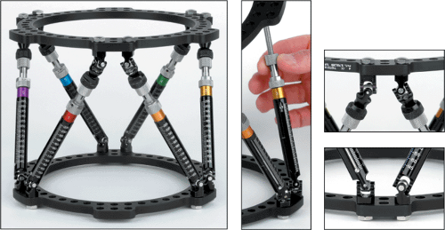 Figure 30.1. One Spatial Frame ring can be repositioned with respect to the other by adjusting strut lengths. (Copyright © J. Charles Taylor.) |
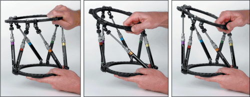 Figure 30.2. A Spatial Frame may be acutely adjusted by hand with all struts in the unlocked position. (Copyright © J. Charles Taylor.) |
Frames can be tapered by using rings of different sizes to make them less cumbersome and safer while descending stairs. Generally 1 to 2 fingerbreadths clearance anterior between the ring and skin and 2 to 3 fingerbreadths posteriorly are adequate (Fig. 30.4). To allow full knee flexion, a 2/3 ring with open posterior is frequently used for proximal tibial fractures. Complete and 2/3 rings range in size from 80- to 300-mm internal diameter and are available in 25-mm increments. Accessory rings and partial rings may be attached to extend the levels of fixation (Fig. 30.5). Standard and short foot plates are available in 155- and 180-mm internal diameters. U plates are also used for foot fixation (Fig. 30.6).
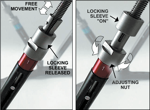 Figure 30.3. Fast Fx struts are free to slide in the unlocked position for acute fracture reduction. The locking sleeve is advanced to lock the strut. The locked strut can still be gradually adjusted by rotation of the nosepiece. (Copyright © J. Charles Taylor.) |
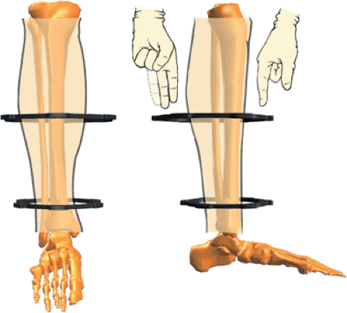 Figure 30.4. Spatial Frames may be tapered and eccentric. Sufficient soft-tissue clearance should be allowed to prevent frame impingement. (Copyright © J. Charles Taylor.) |
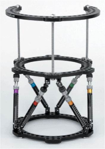 Figure 30.5. A tapered frame consisting of a 180-mm diameter 2/3 ring proximally connected to a 155-mm Spatial Frame, distally, Ilizarov threaded rods. The proximal 2/3 ring with the opening positioned posteriorly allows full knee flexion. (Copyright © J. Charles Taylor.) |
The assembly drawing is shown in Figure 30.7. The open area of a 2/3 ring can be positioned based on surgeon’s choice. Six identifier clips, uniquely colored and numbered 1 through 6, are provided with each frame. Each numbered/colored clip is applied to a strut beginning with strut 1 (which is attached to a tab directly anterior on the proximal ring) and progressing counterclockwise as viewed from the proximal end of the frame.
 Figure 30.6. Additional skeletal stability and prevention of equinus deformity may be gained by fixing the foot to a foot plate or U plate. (Copyright © J. Charles Taylor.) |
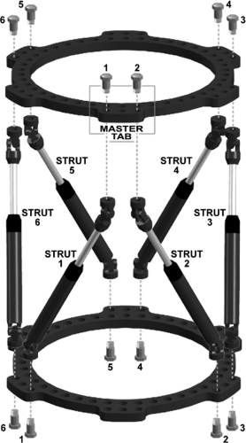 Figure 30.7. Each numbered and colored clip is applied to a strut beginning with strut no. 1 (which is attached anteriorly to the designated master tab) and progressing counterclockwise as viewed from the proximal end of the frame. The computer program assumes the universal joints connecting strut no. 1 and no. 2 to the proximal ring are aligned directly anterior with respect to the reference fragment. Different rotational alignments, especially for more proximal femoral and humeral applications, can be accommodated by changing rotary frame offset. (Copyright © J. Charles Taylor.) |
Adequate Fixation
Threaded, titanium, half pins and/or tensioned 1.8-mm diameter stainless-steel wires were designed to be used with the Spatial Frame. To minimize the number of pins and wires, their placement should be optimized to provide the greatest stability within anatomic constraints. The entire length of the anterior/medial tibia is available for half pin fixation. Four millimeter and 5-mm titanium half pins are used for adolescents and small adults. Usually 6-mm half pins are used in large children and adults.
Long fragments are fixed with at least two and often three half pins in different planes. Pins should be spread longitudinally along a significant portion of each fragment but out of the zone of soft-tissue injury (Fig. 30.8). Obviously this is not always possible.
Shorter peri-articular fragments are fixed with at least two multiplanar half pins at approximately 70 degrees to each other. Adding a single olive wire in the coronal plane adds significant stability to a short fragment.
Alternatively, three 1.8-mm olive wires can be used to stabilize a short proximal or distal fragment (Fig. 30.9). The crossing angle of these wires must be optimized within anatomic limits. Olives should block the fragment from each side and the third olive wire should be blocking the fracture obliquity. Stability for a very short proximal tibial fragment
can be increased by transfixing the tibia and fibula at the level of the fibular head with a tension wire.
can be increased by transfixing the tibia and fibula at the level of the fibular head with a tension wire.
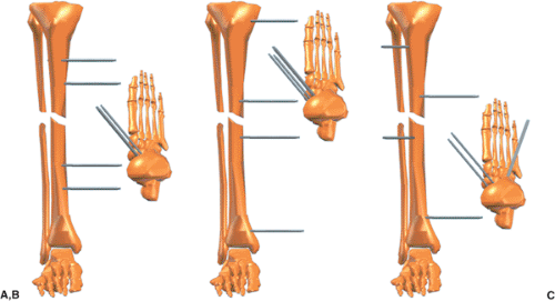 Figure 30.8. A. The surgeon should not limit mechanical stability by two sets of parallel pins. B. Fracture stability is significantly improved by extending the working length in each fragment. C. Stability is further increased by inserting pins in different planes, achieving multiplanar fixation. (Copyright © J. Charles Taylor.) |
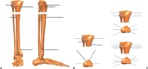 Figure 30.9. A. Short peri-articular fragments can be stabilized with two or three multiplanar half pins. B. Stability is improved significantly by at least one tension wire. C. For short extra-articular fragments, good stability is provided by three multiplanar tension wires. Four multiplanar wires are used for intra-articular fractures such as a bicondylar tibial-plateau fracture. (Copyright © J. Charles Taylor.) |
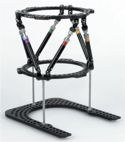 Figure 30.10. The accessory foot plate or U plate is attached to the Spatial Frame with threaded rods. (Copyright © J. Charles Taylor.) |
For very short, distal, tibial fragments, transosseous wires can be used as needed in the syndesmotic region. Intermediate length fragments may be fixed with a combination of wires and half pins.
The foot may also be included at least temporarily for fracture stability, soft tissue immobilization, and prevention of equinus contracture. A distal shaft fracture with significant soft-tissue injury and especially with peripheral nerve injury or closed head injury should have the fixation extended to the foot at least temporarily (Fig. 30.10). The foot plate is attached to the distal ring of the Spatial Frame with threaded rods. Usually a combination of olive wires and half pins are placed in the calcaneus and two wires are placed in the metatarsals (Fig. 30.11). Shorter frames may be constructed with short body struts. Tapered
and open-section frames may be applied. Segmental fractures are usually treated with a ring or 2/3 ring for each major fragment (Fig. 30.12).
and open-section frames may be applied. Segmental fractures are usually treated with a ring or 2/3 ring for each major fragment (Fig. 30.12).
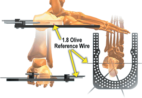 Figure 30.11. Angled wires and/or pins are used in the calcaneus. Usually two wires are used in the forefoot (not shown) at the level of the metatarsal necks. (Copyright © J. Charles Taylor.) |
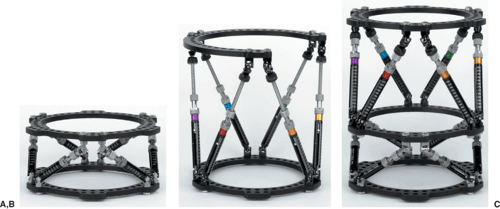 Figure 30.12. A. Shorter struts allow more stable fixation when indicated. Accessory rings could be added to extend level of fixation. B. The component system permits custom frames such as this tapered open-section frame for distal femoral application. C. Each ring has six tabs and can serve as the intermediate ring for a segmental application. Spatial Frames come preassembled or can be assembled from components. (Copyright © J. Charles Taylor.) |
Steerage Pin
Oblique fracture stability can be improved by using steerage pins on either side of the fracture (1). These pins should be angled 15 to 20 degrees from the transverse plane along the plane of the fracture (Fig. 30.13). These pins will cause dynamic interfragmentary compression
with weight bearing and minimize fracture shear. It is still beneficial if only one steerage pin is used.
with weight bearing and minimize fracture shear. It is still beneficial if only one steerage pin is used.
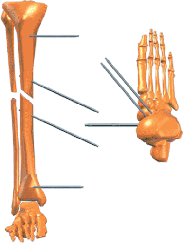 Figure 30.13. Steerage pins are angled 15 to 20 degrees, approximating the major oblique-fracture plane. They are placed on each side of the fracture and are used with other pins and/or wires. Steerage pins increase interfragmentary compression and reduce shear at the fracture site during ambulation. (Copyright © J. Charles Taylor.) |
Surgery
Positioning
General, spinal, or continuous epidural anesthetics may be used as indicated. The patient is positioned supine on a padded radiolucent table top. The most user-friendly tables contain no metal rails (even peripherally) to interfere with visualization with the image intensifier. The image intensifier should be positioned on the opposite side of the injury. A well-padded tourniquet is placed about the proximal thigh but generally is only used during debridement of open fractures. Even if used for debridement, the tourniquet should be deflated prior to pin and wire insertion. Longitudinal traction through a calcaneal wire may be used to improve overall alignment, but it is rarely used. A few folded towels are used to elevate the leg segments as needed as the frame is applied.
Pin and Wire Technique
Pin and wire location and insertion technique are some of the most important factors for patient tolerance, frame longevity, and minimization of need for additional surgery. Bayonet point wires with cutting relief are the safest for metaphyseal and especially diaphyseal bone (Fig. 30.14). Wires are inserted percutaneously to the near cortex, then slowly drilled across both cortices with frequent pauses to prevent overheating, and tapped through the far soft tissue. The wire is bathed in saline for additional cooling. The surgeon should strive to achieve bicortical purchase with wires and pins to enhance mechanical purchase and decrease thermal necrosis. If burned bone is in the flutes of the predrill for half pins or on the tip of the emerging bayonet tipped wire, do not use that pin or wire. The small incision to insert the drill sleeve or release the skin for the olive is closed with a simple suture.
Frame Application
The Spatial Frame is assembled with two rings and six medium FastFx struts in their unlocked position (see Fig. 30.7). After choosing the approximate level for one ring, the surgeon marks the skin. Then the surgeon marks the skin 18 cm away for the position of the second ring (Fig. 30.15). The surgeon then slides the frame onto the leg (Fig. 30.16). The frame need not be centered longitudinally over the fracture. Make a short longitudinal incision
for a sagittal-plane half pin. Using a five-hole Rancho Cube as a drill guide (Fig. 30.17), the surgeon drills a pilot hole for the half pin. After inserting the half pin (Fig. 30.18), the surgeon attaches it to an appropriate length Rancho Cube while maintaining the desired soft-tissue clearance (Fig. 30.19). The Rancho Cube is attached to the Spatial Ring via the inner tier of holes at the anterior position (Fig. 30.20) on the master tab, the junction of the no. 1 and no. 2 struts. Using as long a Rancho Cube as possible, the surgeon inserts a half pin in the anterior-medial plane off the proximal face of the proximal ring (Fig. 30.21). Using a Rancho Cube as a drill guide (Fig. 30.22), the surgeon inserts a half pin in the sagittal plane on the proximal portion of the distal fragment (Fig. 30.23). Maintaining 1 to 2 fingerbreadths of soft-tissue clearance, the surgeon then attaches the Rancho Cube to the pin in the distal fragment (Fig. 30.24). The Rancho Cube is attached to the distal ring in the anterior hole (Fig. 30.25).
for a sagittal-plane half pin. Using a five-hole Rancho Cube as a drill guide (Fig. 30.17), the surgeon drills a pilot hole for the half pin. After inserting the half pin (Fig. 30.18), the surgeon attaches it to an appropriate length Rancho Cube while maintaining the desired soft-tissue clearance (Fig. 30.19). The Rancho Cube is attached to the Spatial Ring via the inner tier of holes at the anterior position (Fig. 30.20) on the master tab, the junction of the no. 1 and no. 2 struts. Using as long a Rancho Cube as possible, the surgeon inserts a half pin in the anterior-medial plane off the proximal face of the proximal ring (Fig. 30.21). Using a Rancho Cube as a drill guide (Fig. 30.22), the surgeon inserts a half pin in the sagittal plane on the proximal portion of the distal fragment (Fig. 30.23). Maintaining 1 to 2 fingerbreadths of soft-tissue clearance, the surgeon then attaches the Rancho Cube to the pin in the distal fragment (Fig. 30.24). The Rancho Cube is attached to the distal ring in the anterior hole (Fig. 30.25).
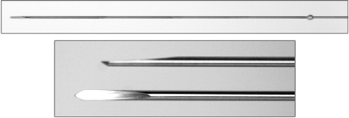 Figure 30.14. Olive wire with close-up of cutting tip. (Copyright © J. Charles Taylor.) |
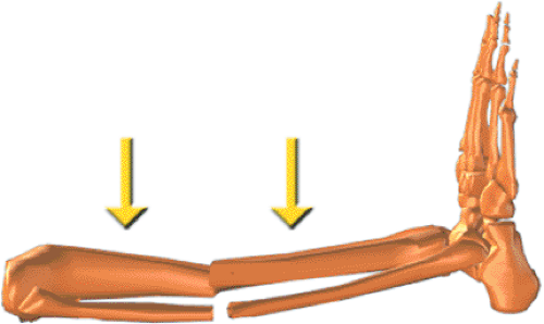 Figure 30.15. Determine the approximate position of one ring, usually on the shorter fragment, and mark the skin. Place a second mark 18 cm from the first for FastFx struts or 15 cm for standard struts. These marks are the approximate positions for the rings. (Copyright © J. Charles Taylor.) |
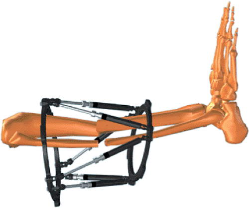 Figure 30.16. The frame is slid over the leg. (Copyright © J. Charles Taylor.) |
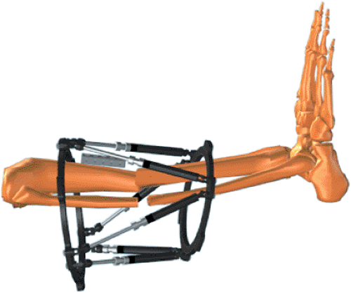 Figure 30.17. Lay a long Rancho Cube along the tibial crest for a sagittal pin. (Copyright © J. Charles Taylor.) |
 Figure 30.18. Using the Rancho Cube as a drill sleeve guide, the surgeon drills the appropriate pilot hole and inserts a half pin by hand. (Copyright © J. Charles Taylor.) |
Related posts:

Stay updated, free articles. Join our Telegram channel

Full access? Get Clinical Tree


