The Reversed Prosthesis
François Sirveaux
Daniel Molé
Pascal Boileau
F. Sirveaux: Clinique de Traumatologie et d’Orthopédie, Nancy, France.
D. Molé: Clinique de Traumatologie et d’Orthopédie, Nancy, France.
P. Boileau: Hôpital de l’Archet, Nice, France.
INTRODUCTION
Although Grammont et al.26 developed the reversed shoulder prosthesis nearly 20 years ago, it took two decades for this concept to be fully accepted in both Europe and North America. The reticence of many surgeons to accept this seemingly radical concept was because of the nonanatomic design and a long list of prior constrained prosthetic designs that led to dismal clinical failures. Currently, in Europe, the reversed shoulder prosthesis has become an important standard of care in the treatment of difficult reconstructive problems of the shoulder. Indeed, it has become one of the most commonly used prosthesis to treat rotator cuff tear arthroplasty and failed prior arthroplasty in the setting of soft-tissue loss. As such, it has greatly changed the habits of most surgeons who must confront these difficult problems. The reason for this great shift in clinical approach is the dramatic improvement of functional outcome because of the geometry of this prosthesis. In fact, the concept of “limited goal surgery,” by Neer et al.,38 in the case of rotator cuff tear arthropathy and revision surgery has become antiquated in many cases because of the reliability of the reverse prosthesis in compensating for loss of rotator cuff function.
It is widely accepted that the outcome of an anatomic prosthesis depends on the status of the rotator cuff. Rotator cuff insufficiency often results in anterosuperior subluxation of the humeral head, which hinders deltoid action. The loss of a fixed fulcrum for rotation thus leads to loss of active elevation of the arm. Many surgeons attempted to design a constrained or reversed prosthesis that compensated for this biomechanical deficiency, but virtually all failed because of faulty biomechanical design. Grammont’s26 legacy of the reversed shoulder prosthesis was based on his belief in the concept of reestablishing a fixed fulcrum for rotation while respecting the forces across the glenoid. His design allowed for both of these goals to be achieved. This chapter will discuss the history and biomechanical aspects of the reversed prosthesis as well as the surgical technique, indications, and results.
HISTORY AND DESIGN RATIONALE
In the absence of an effective rotator cuff, active elevation is hindered because there is loss of the normal fulcrum for rotation that allows the deltoid to lift the arm. In fact, the orientation of the deltoid muscle fibers causes superior movement of the humeral head because the force coupled with the rotator cuff is now imbalanced. The coracoacromial arch forms the last barrier to this superior movement. The only way to restore shoulder motion in this situation is to restore a fixed fulcrum for rotation so the deltoid can have a sufficiently efficient lever arm to elevate the humerus. This can be achieved with the reversed shoulder prosthesis designed by Grammont.26 Prior reversed shoulder designs have attempted to apply biomechanical principles normally appropriate for hip arthroplasty.8,9,32,34,41 These designs failed as the result of a high rate of glenoid loosening because they all moved the fulcrum for rotation lateral to its normal position and thus created increased shearing forces across the glenoid during elevation.41
The principle of a reversed prosthesis was suggested in the 1970s by Neer.36 The advantage of a reversed design was to alter the vector of forces starting from the center of rotation to create centripetal forces, which would maintain the compression of the humeral cup onto the sphere during the elevation. The use of a large-diameter sphere was theorized to increase the mobility and lever arm of the deltoid by lateralizing the greater tuberosity.3,20,36 Neer observed,
however, that this type of implant would not reestablish active external rotation when the infraspinatus was torn. Thus, he abandoned this line of implant design in 1974. Moreover, all prostheses using a fixed rotation center outside the scapula were given up for the same reasons (Reeves prosthesis,42 Kolbel,31 Kessel,6,52 and Jefferson and Fenlin prostheses,20 Gerard and Lannelongue prosthesis,24 and Liverpool and Beddow prosthesis2). Three component prostheses suggested by Buechel et al.7 and Gristina and Webb27 remained at the experimental stage and never progressed further.
however, that this type of implant would not reestablish active external rotation when the infraspinatus was torn. Thus, he abandoned this line of implant design in 1974. Moreover, all prostheses using a fixed rotation center outside the scapula were given up for the same reasons (Reeves prosthesis,42 Kolbel,31 Kessel,6,52 and Jefferson and Fenlin prostheses,20 Gerard and Lannelongue prosthesis,24 and Liverpool and Beddow prosthesis2). Three component prostheses suggested by Buechel et al.7 and Gristina and Webb27 remained at the experimental stage and never progressed further.
In 1987, Grammont et al.26 (Dijon, France) developed an original reverse prosthesis design, based on experimental biomechanical studies. The aim of Grammont et al. was to design a stable prosthesis by improving deltoid efficiency while limiting risk of glenoid loosening. According to the work of Fischer and coworkers,21 a prosthesis was conceived in which the center of rotation remained inside the glenoid. This geometry was achieved by fixing a hemisphere to a baseplate covering the glenoid to allow lateralization of the deltoid lever arm while at the same time reducing shearing forces across the glenoid and promoting compression forces across the joint during deltoid contraction and arm elevation (Figs. 26-1, 26-2 and 26-3).
The increase of the deltoid lever arm (torque) is caused by the medial displacement of the center of rotation, and, thus, an increase in the force magnitude exerted by the muscle during elevation (Torque = force × distance) (Fig. 26-2). A study on an anatomic simulator showed that a 10-mm medialization of the center of rotation increased the deltoid torque by 20% to 60%.26 Because of the orientation of the force vector produced by the deltoid, lowering the center of rotation also induces an increase of the lever arm (lowering of 10 mm increases the abduction torque by 30%-60%). The increase of the deltoid forces is related to the middle deltoid tensioning, which improves the efficiency of the contraction of the muscular fibers. Furthermore, the medialization of the center of rotation also increases the abduction component of the anterior and posterior part of the deltoid (Fig. 26-3).
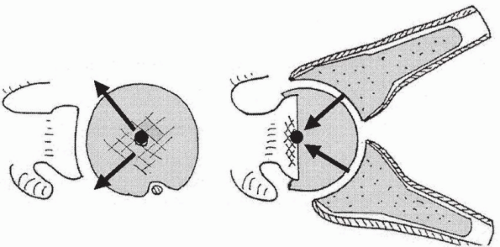 Figure 26-1 Reverse disposal of the prosthesis enables the forces to be focused on the center of the sphere and glenoid baseplate. |
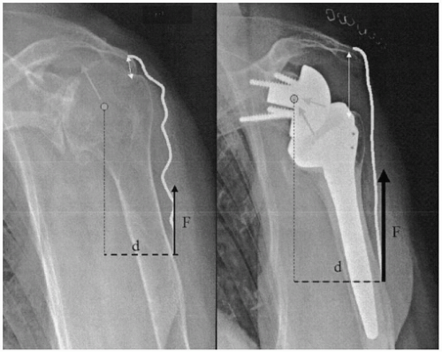 Figure 26-2 Middle deltoid torque is increased because of the medialization of the center of rotation, which increases the muscle lever arm and tension of the muscular fibers. |
Using a large-diameter sphere allows an increase in the range of motion at the level of the prosthesis and increases the stability of a constrained design similar to the design of hip arthroplasty. The choice of a 36-mm or 42-mm sphere corresponds, according to the designer, to the average volume of the joint.1 Beyond 45 degrees, the constraints applicable to the glenoid are centered on the bone/implant interface and participate in joint stability. The medialization and lowering of the rotation center tends to incline the diaphysis and open the angle between the humeral shaft and the scapula pilar. This tends to diminish the shearing constraints, which are persistent at the start of the elevation. For Grammont et al.26 the existence of these constraints justifies the use of a noncemented glenoid implant with a central peg and a divergent fixation by screws fixed to the baseplate.
The initial prototype used by Grammont et al.26 consisted of a cemented glenoidal implant corresponding to two-thirds of a sphere 42 mm in diameter, which would fit on a cylinder prepared with a crown saw. The humeral implant was polyethylene, forming a cup corresponding to one-third of a sphere (Fig. 26-4).
In 1987, Grammont et al.26 reported their preliminary results on eight cases with an average follow-up of 8 years. There were three cases of postradiotherapy necrosis, four cases of revision prostheses, and one case of inflammatory arthritis. The approach included an osteotomy of the acromion. In three cases, patients recovered an active elevation of 100 to 130 degrees, and the author emphasized the swiftness of the functional recovery. From 1989 onward, Grammont conceived the Delta 3, in which the initial model consisted of a sphere screwed on the glenoid
baseplate (Fig. 26-4). Because of the complication of unscrewing the sphere, the fixation of the sphere was modified in 1995 by a Morse taper locked by a central screw. The humeral stem was conical and available in its cemented or uncemented form, covered by hydroxyapatite, and in three different lengths (100, 150, or 180 mm). The proximal part was screwed on the stem and designed with an antirotation fin. The humeral cup was made available in two thicknesses (0 and 6 mm) with the possibility of adding a metallic extension of 9 mm or using deeper versions in case of instability. The Delta prostheses 1 and 2 correspond to an anatomic version of the prosthesis with a metallic head to be fixed on the humeral implant (Delta 1) and an anatomic glenoid implant (Fig. 26-5).
baseplate (Fig. 26-4). Because of the complication of unscrewing the sphere, the fixation of the sphere was modified in 1995 by a Morse taper locked by a central screw. The humeral stem was conical and available in its cemented or uncemented form, covered by hydroxyapatite, and in three different lengths (100, 150, or 180 mm). The proximal part was screwed on the stem and designed with an antirotation fin. The humeral cup was made available in two thicknesses (0 and 6 mm) with the possibility of adding a metallic extension of 9 mm or using deeper versions in case of instability. The Delta prostheses 1 and 2 correspond to an anatomic version of the prosthesis with a metallic head to be fixed on the humeral implant (Delta 1) and an anatomic glenoid implant (Fig. 26-5).
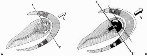 Figure 26-3 Medialization of the rotation center increases the abducting component of the anterior and posterior parts of the deltoid. |
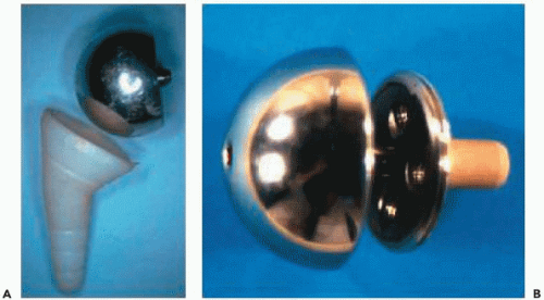 Figure 26-4 Initial prototype of Grammont’s reverse prosthesis (A). Fixation system of the second version of the prosthesis with the sphere screwed on the baseplate (B). |
PLANNING AND SURGICAL TECHNIQUE
Patient Evaluation
In addition to the appreciation of pain, loss of active mobility (pseudo-paralytic), and the usual functional criteria (muscular strength, daily activity, and Constant score), the following points need to be assessed before implanting a reversed prosthesis:
Surgical history: The status of the remaining acromial arch, rotator cuff tendons, and prior surgical approaches used are important to guide the subsequent prosthetic surgery.
External active rotation, elbow to the side (lag sign, belly press test) and in elevation: The patient should be asked about the functional consequences of the deficit, bearing in mind that it might increase if a reversed prosthesis is used.
The passive mobility, especially in anterior elevation and external rotation: The presence of associated stiffness can influence the choice of the approach, because an inferior capsular release is more easily performed through an anterior deltopectoral approach than a superior approach.
The essential integrity of the deltoid and the axillary nerve.
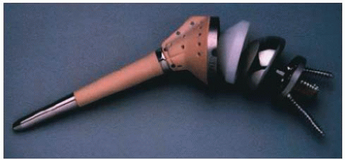 Figure 26-5 Delta prosthesis in its current configuration. |
Preoperative imaging should consist of the following:
X-ray: A true anterior-posterior image with the arm in neutral rotation will demonstrate glenoid wear that may have a bearing on implantation of the component. Superior displacement and disruption of the acromial arch may also be observed in cases of failed treatment of massive rotator cuff tears. An axillary view will demonstrate fixed displacement and glenoid erosion in that plain radiograph as well.
Computed tomography (CT) scan or arthro-CT: These three-dimensional studies allow for assessment of the loss of bone stock, the glenoid orientation in the horizontal plane, and the degree of atrophy and fatty infiltration (Goutallier classification) of the cuff muscles (importance of the teres minor).
Magnetic resonance imaging: Cuff lesions and degree of synovial inflammation can be seen on these images.
Preoperative Planning
Good preoperative anterior and posterior radiographs will allow for proper preoperative templating of the components needed for the surgical reconstruction.
The diaphyseal axis and entry point of the humeral instruments (frequent variations).
The sizes of the metaphysis and prosthetic sphere among the possible choices (diameter 36 or 42 mm). The choice is, in most cases, a 36-mm implant.
The length and diameter of the humeral stem. Usually the stem must be as short as possible (100 mm), and caution should be taken not to oversize its diameter to reduce the risk of fracture. The use of a cemented stem is generally advised.
The level of the humeral cup, making sure to determine a reproducible landmark on the bone (lateral facet of the greater tuberosity).
The glenoidal preparation: location of the entry point on the frontal plane and horizontal plane; orientation and amount of reaming relative to the loss of bone stock and to achieve optimal glenoid positioning; and orientation of the fixation screws of the baseplate.
Surgical Technique
Setup and Surgical Approach
The patient is positioned in a beach-chair position with the affected shoulder completely free from the table. The patient’s head is carefully positioned rotated away from the operative shoulder to ensure good access to humeral preparation. The arm is left free so that manipulation is possible because this helps humeral component insertion. The following two approaches can be used (Fig. 26-6).
The deltopectoral approach allows for adequate inferior exposure to manage complex revision cases and significant contractures. However, a drawback is that it requires the section of the remaining subscapularis tendon and anterior capsule, and, in our experience, the risk of postoperative shoulder instability is greater than with the superior approach.
The anterosuperior approach, although having the disadvantage of compromising the deltoid origin, does allow preservation of remaining inferior soft tissue that may reduce the risk of instability. It is, however, difficult to perform revision cases with component removal from this approach.
The deltopectoral approach presents an advantage because it respects the integrity and insertion of the deltoid;
it also enables an inferior capsular release in case of joint stiffness. Nevertheless, its drawback is that it requires the section of the remaining subscapularis tendon and anterior capsule, which carries a risk of postoperative dislocation.
The anterosuperior approach (along the anterior border of the acromion with division of the anterior deltoid) has the inconvenience of compromising the deltoid insertion; however, it has the double advantage of facilitating the exposure of the humeral head and glenoid in addition to enabling the respect of the anterior stabilizing structures (subscapularis tendon and capsule), decreasing the risk of postoperative instability.
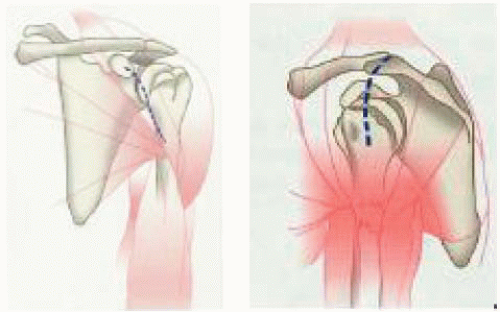 Figure 26-6 Deltopectoral approach and anterosuperior approach. |
Humeral Head Resection and Humeral Reaming (Author’s Preferred Technique)
After resection of the remaining upper cuff, the humeral head is exposed by anterosuperior luxation (arm in extension, external rotation, pushing up on the elbow) when using the anterosuperior approach or by anterior dislocation (arm in extension, abduction and external rotation) when using the deltopectoral anterior approach.
The epiphysis entry hole is drilled at the top of the humeral head just medial to the bicipital groove at a location predetermined from preoperative templating (Fig. 26-7). The guide is introduced, and the humeral head is cut with an oscillating saw. The height of the cut should be consistent with preoperative planning. In the event of stiffness, resection should be slightly more aggressive with the humeral osteotomy somewhat lower than the guide. With the anterosuperior approach, the aim is that the medial edge of the humeral resection should align with the inferior pole of the glenoid.
The approach is one based on surgeon preference. In the case of a deltopectoral approach, the risk of dislocation is more of a concern; therefore it is preferable to position the humerus component in 20 degrees of retroversion. In the case of a superior approach, the risk of dislocation is decreased so the choice of the retroversion angle is less of a concern. In the case of a stiff shoulder, the risk of dislocation is less relevant, whereas the risk of inferior scapular notching is more of a concern; thus, a 0-degree retroversion angle seems preferable. If the shoulder is supple, a 20-degree retroversion angle is preferable to limit the risk of dislocation. Furthermore, if the shoulder is supple, then the glenoidal component can be fixed in such a way to decrease the risk of inferior impingement.
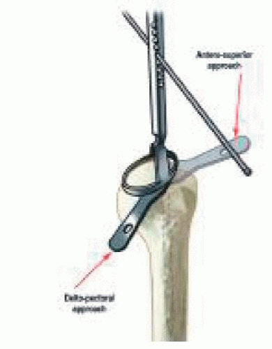 Figure 26-7 Humeral section. |
The metaphysis is then reamed to the appropriate diameter, as guided by preoperative templating, and the intraoperative fit is judged by achieving adequate depth. The diaphysis is prepared to the length and diameter planned preoperatively. After the diaphyseal and epiphyseal parts are assembled, the trial humeral prosthesis is inserted and covered by a cup protector.
The humeral section is performed with a retroversion angle between 0 and 20 degrees, depending on the anatomy of the proximal humerus and choice of the surgeon. A 0-degree retroversion enables us to avoid, in adduction, contact between the medial part of the epiphysis and the scapular pillar. Thus, the risk of scapular notching is decreased. However, the risk of anterior prosthetic dislocation is most likely to be increased. A 20-degree retroversion limits the risk of instability but increases the risk of an inferior glenoid notching.
Exposure and Preparation of the Glenoid
The glenoid surface is prepared with a surfacing rasp, corresponding to the diameter of the chosen implant (Fig. 26-8). Reaming may sometimes require withdrawing the retractors to fit the reamer in place on the glenoid. In case of fragile bone, it is preferable to perform this step manually using a hand reamer rather than reaming with a power drill. Reaming should be performed until a smooth area of the subchondral bone is created. At the completion of the reaming, it is necessary to reposition the retractors and check for any bony prominence that may remain outside the peripheral groove of the reamer. This can impede correct insertion of the glenoid baseplate.
The uncemented glenoid baseplate implant (the diameter having been chosen) is attached to the impactor and then inserted, checking the alignment of the inferior screwing hole with the scapular pillar. The inserter is withdrawn, and the contact between the baseplate and the osseous surface is checked.
The baseplate is then fixed; two threaded head screws are used for the superior and inferior holes, whereas two spherical head screws are used for the anterior and posterior holes. We recommend that initial fixation should be achieved with the two anterior and posterior screws with compression by using adequate drills and gauges perpendicular
to the glenoidal axis. The inferior screw is then positioned and directed toward the axis of the scapular pillar with, ideally, an angle of 30 degrees inferiorly and 10 degrees posteriorly. The use of a gauge is essential so that this screw, normally long, can have an adequate length and stability. The same procedure is used for the superior screw, the purpose being to purchase the screw in the base of the coracoidal apophysis with an angle of 20 degrees superiorly and 20 degrees anteriorly.
to the glenoidal axis. The inferior screw is then positioned and directed toward the axis of the scapular pillar with, ideally, an angle of 30 degrees inferiorly and 10 degrees posteriorly. The use of a gauge is essential so that this screw, normally long, can have an adequate length and stability. The same procedure is used for the superior screw, the purpose being to purchase the screw in the base of the coracoidal apophysis with an angle of 20 degrees superiorly and 20 degrees anteriorly.
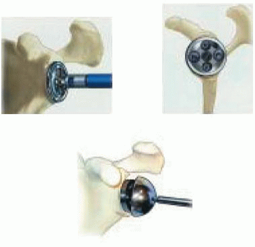 Figure 26-8 Glenoid is exposed by positioning the double point extractor under the axillary border, the points being located on both sides of the triceps tendon and scapular pillar. The retractor pushes down on the superior end of the humerus, which remains protected by the trial prosthesis. Other retractors are positioned anteriorly, posteriorly, and superiorly to the glenoid. Capsula release and its location are decided according to preoperative stiffness. Exposure is completed by resection of the remaining labrum, biceps tendon, and osteophytes, which could compromise the correct positioning of the implant. The central hole is created with the adequate cannulated drill. Its location and direction take into account the orientation of the joint area, analyzed beforehand by computed tomography (CT) scan, and the need for a portioning as low as possible, with a slight inferior tilt. The baseplate can be used as a guide if turned so that it is positioned backward on the glenoid. This tilt helps to limit the incidence of the inferior impingement and scapular notch. The use of a drilling guide can be useful to ensure that the positioning is compatible with inferior screwing. Use of a protected drill enables an adequate width. |
Trial Reduction
The trial sphere with the adequate diameter (36 or 42 mm) is attached to the baseplate. The trial humeral insert is fixed on the humeral implant. The components are then reduced by traction and pushing posteriorly on the humeral epiphysis. Mobility and stability of the shoulder are then checked, as well as confirming the absence of humeroscapular contact with the inferior glenoid. The purpose of this trial is to decide the size of the humeral insert, available in several thicknesses, with the possible use of a metallic extension. The determination of proper soft-tissue tension and placement of a component of adequate thickness are according to surgeon judgment, but the goal is to achieve stability throughout all ranges and maintain a mobile joint. Proper tension of the deltoid is the important criterion, although precise guidelines are not available.
Assembling and Installation of the Final Components
After removal of the trial implants, the sphere is attached to the baseplate by use of a double process of fixation with a central screw and impaction of the Morse taper. The security of this assembling may be checked with a hook.
Related posts:
 Three-Part Fractures: Open Reduction and Internal Fixation, or Arthroplasty?
Anterior Superior Rotator Cuff Tears: Repairable and Irreparable Tears
Arthroscopic Repair of Rotator Cuff Tears
Massive Tears of the Posterosuperior Rotator Cuff
Acute Fractures, Malunions, and Nonunions of the Clavicle
Arthrodesis and Other Salvage Procedures: When Arthroplasty Is Not Indicated
Three-Part Fractures: Open Reduction and Internal Fixation, or Arthroplasty?
Anterior Superior Rotator Cuff Tears: Repairable and Irreparable Tears
Arthroscopic Repair of Rotator Cuff Tears
Massive Tears of the Posterosuperior Rotator Cuff
Acute Fractures, Malunions, and Nonunions of the Clavicle
Arthrodesis and Other Salvage Procedures: When Arthroplasty Is Not Indicated
Stay updated, free articles. Join our Telegram channel

Full access? Get Clinical Tree


