, Paul D. Siney1 and Patricia A. Fleming1
(1)
The John Charnley Research Institute Wrightington Hospital, Wigan, Lancashire, UK
It is hoped that the whole range of sockets in time will be replaced by the one single type and size of pressure injection design which can be cut down to suit all sizes of adult acetabulum. The very small (35 mm diameter) socket with offset bore will be the only exception. (1979).
A surgeon, not familiar with either the history of evolution of the cup design or the method of measurement may find the statement “… “one type and size which can be cut down to suit all sizes….” baffling.
Evolution of the design of the Charnley cup has received little attention. The reason for this is by no means clear. Was it the introduction of the new plastic, ultra high molecular weight polyethylene for its manufacture, was it the small 22.225 mm diameter head of the femoral component, the well documented details of surgical technique, or merely the spectacular clinical success of the operation? Wear of the cup presented much later. Design, probably interpreted as “size,” was merely a side issue. The original, scalloped edge design, which has been adopted as the logo both of the John Charnley Trust and the John Charnley Research Institute, was followed by the flanged pressure injection cup (PIJ), and then the ogee-flanged cup. The changes had a purpose – to give stability of the cup at the trial and to improve containment and pressure of cement injection at the final insertion. Surgeons who did not follow the evolution of the cup design have missed its importance in clinical practice.
The Bore of the Cup
In the manufacture of the cup the bore is central. The depth of the bore is that of the radius of the femoral component with a 2 mm parallel lead-in section (Fig. 27.1).
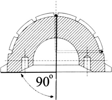
Fig. 27.1
Diagram of the bore of the cup. The depth of the bore is equal to the radius of the head of the femoral component with a 2 mm parallel lead-in section
The Original UHMWPE Scalloped Cup Design
The hemispherical cup with a scalloped edge was the standard design (Figs. 27.2 and 27.3). Its face was chamfered. It could be used right or left, anterior or posterior, as long as the wire marker was in the coronal plane. At insertion the cup was held in a pair of stout artery forceps; the self-ejecting cup holder came later. Since the cup dimensions could not be altered, except by choosing a small or a large size, the measurements were taken from the scalloped margin and not from the cup wall. The two sizes available were 50 mm and 47 mm diameter (“for the longest life of a socket the optimum size of the femoral head will be half that of the external diameter of the socket”). The cup did fit within the prepared acetabular cavity since the preparation with the reamers was towards the opposite shoulder (Figs. 27.4, 27.5, 27.6 and 27.7).
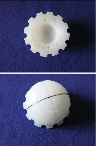
Figs. 27.2 and 27.3
The original, scalloped edge, Charnley cup, front and back views
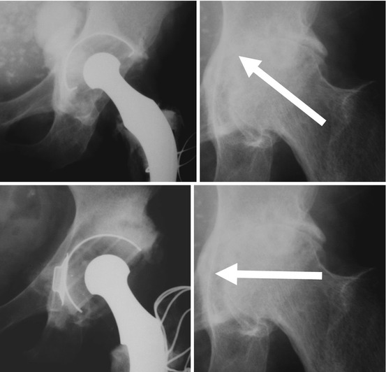
Figs. 27.4, 27.5, 27.6 and 27.7
Original technique of reaming the acetabulum
The Flanged Cup: Pressure Injection Cup (PIJ) (Figs. 27.8 and 27.9)
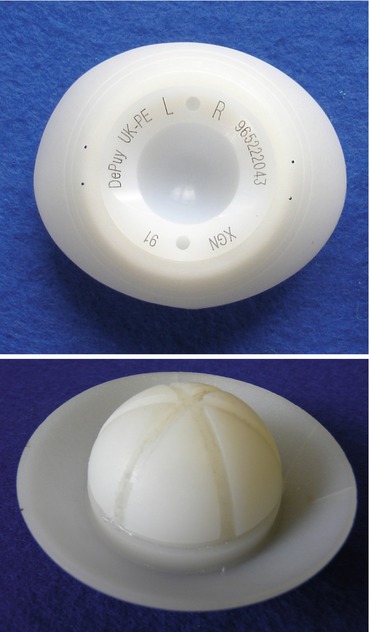
Figs. 27.8 and 27.9
Acetabular cup with a flange, front and back views
With preparation of the acetabulum in the transverse direction (Nov 1970) the superior margin of the acetabulum was no longer covered by the rim of the cup allowing escape of the cement. The solution was … “to design the cup with an oval flange inclined at 45° away from the face.” Thus the flanged PIJ cup was designed. Since the bore of the cup was symmetrical the cup could be used right and left – as long as the PIJ flange was always superiorly. The trimming of the flange to size and the shape of the acetabular cavity improved the fit, stability of the cup at insertion, as well as cement injection.
The Long Posterior Wall Cup (LPW) (Fig. 27.10)
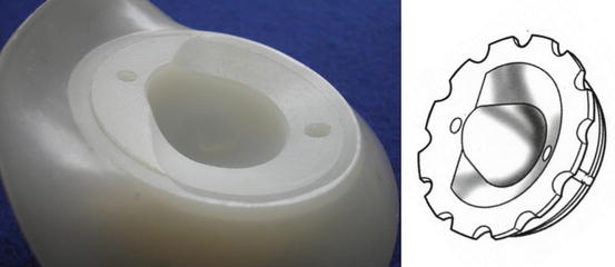
Fig. 27.10
Long posterior wall cup
The concept of the LPW cup is best understood if the method of cup machining from a solid hemisphere is taken into account. Any cup is essentially a hemisphere with a flat face. The central bore will accept the head of the femoral component, the face is chamfered to put off the moment of impingement of the neck of the stem. If only three quarters of the circumference is chamfered the remaining part of the flat face forms an extension of the bore – the long posterior wall. Such a cup must not be placed in anteversion “… because this would increase the projection of the posterior wall and could cause impingement against the back of the neck in a fully extended position of the hip.” It was introduced in May 1972 probably to placate some surgeons who experienced a high incidence of post-operative dislocation using a posterior approach to the hip joint.
Related posts:
 Arthroplasty of the Hip: A New Operation
 Results of Low-Friction Arthroplasty of the Hip Performed as a Primary Intervention
 Revision for Recurrent or Irreducible Dislocation
 Increasing Follow-Up: Changing Age Patterns
 Bone-Cement Interface: The Cup: Radiographic Appearances
 Factors Affecting Wear of the UHMWPE Cup
Stay updated, free articles. Join our Telegram channel

Full access? Get Clinical Tree


