The spinal column forms the keel of the human body and is exposed to a variety of metabolic, mechanical, and circulatory stresses. Many of these stresses can lead to acute or chronic syndromes. Back pain is a symptom. In some cases, the symptom can be matched to a specific diagnosis, but in many cases this is not possible. Back pain is common in the industrialized world. Very rarely does an individual never suffer from back pain in his or her lifetime. Various studies have demonstrated that up to 80% of the population will suffer from back pain. Approximately 30% of the population has back pain at any moment. The cost of treating back pain is high; the cost of disability payments to workers with back pain may be two or three times the cost of treatment. With increased concern over medical spending, it is clear that diagnosis and treatment of back problems are of crucial importance for the individual and for society. This is not always an easy task, as is illustrated by the example of a prolapsed disk. In light of the fact that myelography (Hitselberger and Witten 1968), CT (Wiesel et al. 1984), and MRI (Boden et al. 1990, Jensen et al. 1994) can demonstrate prolapsed disks in a relatively high percentage of asymptomatic patients, the physician may not automatically presume that the presence of a prolapsed disk on imaging is the cause of symptoms in a patient suffering from pain in the back and legs. The enormous number of operations performed to treat prolapsed disks suggests that this sort of reasoning is widespread in day-to-day practice. The presumption that an imaging abnormality is the cause of the patient’s pain is not always correct. Surgical treatment based on erroneous diagnostic decisions can have long-lasting consequences for the patient. Symptoms may persist because the surgically treated disk was not the cause of the symptoms, but a purely incidental finding. The persisting symptoms might then be categorized as a “post-discectomy syndrome,” and not infrequently fusion of the affected segment of the spine is performed. The authors emphasize the importance of precise diagnosis prior to surgery on the lumbar spine (Castro et al. 1995) because the sequelae of an operation based on a faulty diagnosis can be more detrimental to the patient’ s health than the original disorder. The history and clinical examination are of extreme importance for a precise diagnosis. The changes documented in diagnostic imaging studies must always be evaluated in light of the patient’ s history and the findings of the clinical examination. The diagnostic significance of provocative tests such as discography or diagnostic infiltration such as selective nerve root blocks in the evaluation of back symptoms will be discussed in detail in the following sections.
References
Boden SD, Davis DO, Dina TS et al. Abnormal magnetic resonance scans of the lumbar spine in asymptomatic subjects; a prospective investigation. J Bone Joint Surg. 1990; 72-A: 403
Castro WHM, Bongartz G, Schulitz KP. Stellenwert der CT-Diskographie in der differenzierten Therapie des Bandscheibenvorfalles. Deutsches Ärzteblatt. 1995; 92: 352
Hitselberger WE, Witten RM. Abnormal myelograms in asymptomatic patients. J Neurosurg. 1968; 28: 204
Jensen MC, Brant-Zawadzki MN, Obuchowski N, et al. Magnetic resonance imaging of the lumbar spine in people without back pain. N Engl J Med. 1994; 331: 69
Wiesel SW, Tsourmas N, Feffer, et al. A study of computer-assisted tomography. The incidence of positive CAT scans in an asymptomatic group of patients. Spine. 1984; 9: 549
8.2 Clinical Standard Examination
The standard examination for the spine is similar to the procedure for the examination of the rest of the musculoskeletal system. However, physical examination techniques and neurologic examination play a more important role (Table 8.1). Performing the respective individual steps of the examination with the patient standing, sitting, and supine is a proven approach during inspection, palpation, and range-of-motion testing.
• History • Inspection • Palpation • Range-of-motion testing and manual medicine examination • Neurovascular examination • Diagnostic imaging studies |
The examination begins when the patient’ s name is announced in the waiting area. Observe how the patient arises from the chair. Are arm rests used? Is he or she standing erect? Observe the patient’ s gait. Note any pain-related behaviour such as groaning or grimacing. Are ambulatory aids used? This period of observation and assessment is invaluable because it provides an opportunity to note how the patient functions outside of the examination room. Document your observations. Upon occasion, the formal examination may be different from these informal observations.
The formal examination begins by obtaining the history. Usually this will provide the basis for a working diagnosis. Next, inspect the patient’ s torso and cervical spine from behind. The patient should be undressed for this examination. Note any deviations from vertical, shoulder or pelvic obliquity, defective posture, scoliosis, and muscle contour. When inspecting the patient from the front, document any asymmetry in the face, neck, and rib cage, and note the muscle contour and skin folds.
The next phase of the examination is palpation of the posterior aspect of the spine to identify painful points at the spinous processes, vertebral articulations, transverse processes, capsular ligaments, and musculature of the back. Palpation can verify paravertebral spasms. It is important to exclude peripheral causes of pain in radiating pain syndromes by examining adjacent joints. These include primarily the sacroiliac joints, hips, and shoulders. After palpation, preliminary range-of-motion tests are performed for the various segments of the spine in all three planes of motion. Again, adjacent joints should be examined to exclude referred pain. Once you have an initial overview and have assessed the range of motion of the spine, specific physical examination techniques help to more precisely localize and quantify dysfunction. Finally, neurologic examination is performed to exclude sensory deficits and paralysis of the upper and lower extremities. This includes testing intrinsic muscular reflexes and testing for nerve stretch signs. The standard examination procedure may be supplemented by special tests detailed in the following section depending on the tentative diagnosis.
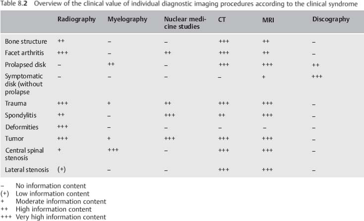
The tentative diagnosis arrived at during clinical examination can be verified by diagnostic imaging studies. The choice of modalities supplementing plain radiography will depend on the working diagnosis. For example, CT with its higher contrast between bone and soft tissue is more suitable for visualizing changes in bone than MRI, whose advantage lies in its high-resolution visualization of soft tissue. Table 8.2 provides an overview of the respective value of the individual diagnostic imaging modalities.
Patient History
As in all other areas of medicine, diagnosis of acute and chronic spinal disorders initially relies on obtaining a history. Chronic symptoms of underlying degenerative changes usually occur in the third or fourth decade of life and are either due to repetitive overuse or misuse or occur as a response to the natural aging process. These symptoms have often been present in a milder form for years or even decades, and they may be intermittent or totally asymptomatic for long periods. Radiating pain often has its origin in the spinal column. Conversely, extravertebral disorders may initially manifest as pain in the spine.
| Spinal causes | Extraspinal causes |
| Discogenic Arthrogenous Spondylolisthesis Muscle or ligament insufficiency Osteoporosis Osteopathy Fracture Spondylitis, vertebral osteomyelitis Tumor, metastasis Ankylosing spondylitis Psoriatic arthritis Reactive spondylarthritis Baastrup disease Coccygodynia | Urologie causes Gynecologic causes Neurologic causes Intra-abdominal causes Psychological causes |
Table 8.3 provides an overview of the various vertebral and extravertebral causes of pain in the low back.
Kramer (1994) differentiates between discogenic pain and joint or ligamentous pain in discussing the cause of pain in the low back. The former is characterized by a sudden onset that is dependent on position and stress. Hip and knee flexion usually alleviate the symptoms. Joint and ligamentous pain in the low back begins gradually and is characterized by a chronic, recurrent course. Pain is often more intense in the evening than in the morning.
Obtaining a detailed history often permits a differentiation to be made between disk pain, as in a prolapsed disk, and joint pain, as can occur in facet syndrome (Tables 8.4 and 8.5).
Ask the patient to describe the symptoms as precisely as possible. The following questions are helpful:
Where?
How?
When?
How long?
• Sudden onset • Erratic development • Position dependent • Pain increased by coughing, sneezing, and pressing |
It is important to localize the pain as precisely as possible. Is it solely low-back pain, as in ankylosing spondylitis, or low-back and leg pain as in a prolapsed disk? Is pain concentrated at one point or does it radiate? The former suggests a muscular cause; radiating pain requires further distinguishing between radicular and nonradicular pain. Classic radicular pain, such as occurs with a prolapsed disk, is characterized by pain limited to one dermatome, occasionally in combination with sensory dysfunction and loss of strength in the muscle supplied by the nerve root. Nonradicular radiating pain, such as occurs with facet syndrome, is often diffuse, not limited to any particular dermatome, and rarely extends beyond the knee or elbow.
It is important to inquire about sensory or motor deficits. Ask the patient to describe these in detail. Inquire specifically about bowel and bladder dysfunction and, in addition, about alteration in sexual sensation or sexual function. The history can provide important information for differentiating radicular from nonradicular pain, and can permit an inference of the level of the affected segment. Bladder or rectal paralysis can occur with lesions in the cauda equina or conus medullaris. Weakness in dorsiflexors of the foot is attributable to a lesion of L5; weakness in the plantar flexors is attributable to a lesion of S1.
• Dull or stabbing pain in the low back • Pseudoradicularpain radiating into both legs • Pain rarely extends beyond the knee • Radiating pain is difficult to localize • Pain cannot be reliably localized in a specific dermatome • Pain increases during the day • Lying down eases pain |
Prolapsed disk | Pain increased by coughing, |
Facet syndrome | Pain in the small of the back |
Spinal stenosis | Intermittent spinal claudication |
Ankylosing | Deep-seated nighttime pain in |
spondylitis | the small of the back |
| Age | Clinical syndrome |
First decade of life | Torticollis, Klippel—Feil syndrome |
Second decade | Scoliosis, Scheuermann disease |
Second to fourth decades | Ankylosing spondylitis |
Third to fifth decades | Discogenic disorders |
Fifth to eighth decades | Spinal stenosis |
Where the pain is chronic and progressive, a spinal tumor must be excluded. Inquire in detail about conditions that provoke the pain. For example, increased intra-abdominal pressure such as coughing, sneezing, or pressing increases intrathecal pressure and can produce pain in discogenic disorders. Spinal stenosis characteristically causes symptoms when the patient stands or walks, referred to as neurogenic claudication. Increased lumbar lordosis with these postures will narrow the.spinal canal. The patient will finding walking uphill easier than walking downhill. Forward flexion typically alleviates pain. Vascular claudication must be excluded. Typically, vascular claudication is worse with exercise and improves with sitting. With vascular claudication there may be findings of decreased peripheral pulses or diminished vascular indices. Consultation with a vascular surgeon may be appropriate.
| Idiopathic neuromuscular |
| Infantile cerebral palsy |
| Poliomyelitis |
| Spinal muscle atrophy |
| Cerebrospinal ataxia |
| Muscular dystrophy |
| Other disorders |
Congenital |
| Developmental disorders |
| Failure of segmentation |
Neurofibromatosis |
Collagen development disorders |
| Marfan syndrome |
| Ehlers-Danlos syndrome |
Chondrodystrophy |
Osteogenesls Imperfecta |
Several typical syndromes are summarized in Table 8.6.
The patient’ s age should always be considered. As Table 8.7 shows, certain syndromes become clinically relevant in specific age-groups.
Not all spinal disorders involve pain. An example of this is scoliosis that is rarely painful in juveniles. However, other aspects of the history are important in this clinical syndrome. First, it is important to determine the extent to which other family members are affected by the disorder. Inquire about the extent of their respective deformities. It is helpful to query the patient about complications during pregnancy and birth, motor development, neuromuscular dysfunction, and other diseases such as connective-tissue disorders (Marfan syndrome or Ehlers-Danlos syndrome) or other syndrome disorders such as von Recklinghausen disease that are frequently associated with scoliosis (Table 8.8). The amount of curvature and the patient’ s physical maturity are factors used to predict curve progression (Table 8.9).
After an accident, inquire about the precise mechanism of injury, the use of seat belts, headrests, and air bags, cuts, bruises, impacts inside a vehicle, emergency medical treatment, and the degree of damage to the vehicle. The forces acting on the body can provide important information about the structures that may be injured. An example is injury to the cervical spine after an acceleration or deceleration mechanism (whiplash). Without a history of an accident this is very difficult to diagnose because most patients in whiplash associated disorders (WAD) report symptoms that cannot be correlated with corresponding traumatic physical examination findings, and imaging studies are usually normal. Elements needed to define WAD often include an unexpected or surprise impact, an unsupported head and neck, and an immobilized torso. This indicates that no direct trauma has occurred to the cervical spine. Blunt trauma to the head resulting from collision with the windshield excludes the diagnosis of WAD from a rear-end collision (Ludolph 1995) (Table 8.10).
• Family history • Complications during pregnancy or birth • Motor development during childhood • Associated disorders • Neurologic deficits • Time of menarche • Signs of cardiopulmonary insufficiency • Time of initial diagnosis • Increase in the deformity |
• Was the patient surprised by the accident, or could it be anticipated by looking in the rear-view mirror? • From which side did the collision occur? • Did the patient’ s head hit the windshield or other parts of the passenger compartment, or did it move freely? • Was the patient wearing a seat belt? • Did the car have air bags? • Was the patient’ s head stopped by a headrest? • What was the exact sitting position of the patient when the collision occured? |
The report of the Quebec Task Force on Whiplash-Associated Disorders is important in clinical spine science. In the exhaustive synthesis of the literature, the task force identified five grades of whiplash-associated disorder (Table 8.11). These grades are not diagnoses but serve as adequate descriptions of the presentations, given that spine science has not yet identified with certainty what the injuries are. An increasingly important question is whether a technical analysis of the collision has been prepared; a change in velocity due to a collision provides information about the amount of force and resulting biomechanical stress (Weber 1995, Castro et al. 1997).
The history should include occupational and leisure activities. Repetitive overuse and misuse can be the cause of back pain.
Epidemiologic studies have demonstrated a relationship between low-back pain and the effects of vibration, for example in helicopter pilots or truck and tractor drivers. Behavior when sitting and posture appear to be more significant than the vibration itself with respect to the incidence of low-back pain.
Discogenic disorders of the cervical spine are less frequent than those of the lumbar spine. Repetitive torsional stresses, high axial forces, and asymmetric loads on the cervical spine over an extended period of time are particularly detrimental. Military pilots and meat packers are occupational groups with these stresses.
| Grade | Clinical presentation |
| 0 | No complaints about the neck, no physical signs |
| I | Neck complaints of pain, stiffness, or |
| II | Neck complaints and musculoskeletal sign(s)* |
| III | Neck complaints and neurologic sign(s)+ |
| IV | Neck complaints ancffracture/dislocation |
* Musculoskeletal sign(s) include decreased range of motion and point tenderness
+ Neurologic sign(s) include decreased or absent deep-tendon reflexes, weakness, and sensory deficits Symptoms and disorders manifest in all grades include deafness, dizziness, tinnitus, headache, memory loss, dysphagia, and temporomandibularjoint pain
| IMVIinimal-stress sports | Higher-rate sports |
Swimming | Tennis |
The history should also include the patient’s athletic activities. Sports that involve axial loads on the spinal column or strong torsional motions of the spinal column are particularly detrimental to the back. Sports that place minimal stresses on the spine include those whose motions relieve stress on the spine or those involving gentle, harmonic motions (Castro and Schilgen 1995) (Table 8.12).
Remember to ask about private circumstances that may coincide with the occurrence of symptoms. Often, factors such as personal or occupational problems coincide with the onset of symptoms. A history of the patient’ s psychosocial situation is particularly important for patients with chronic back pain. We know that the longer the duration of occupational disability the lower the chance of rejoining the workforce. The degree to which the patient is satisfied with his or her job is highly significant in this context. Carefully inquire about the patient’ s psychosocial situation with respect to any planned surgical treatment. An unfavorable psychosocial profile can doom even the most carefully performed operation to failure. Patients in a worker’s compensation setting show significantly poorer response to treatment than do patients who are not.
It is important to inquire about smoking since there is a known correlation between smoking and discogenic back pain.
To complete the patient’ s history, ask about previous therapy. Compile a list of operations, physical therapy, medication, and injections that is as comprehensive as possible and documents the respective success of these treatments. You will often find that patients with chronic back pain have previously consulted other physicians and that comprehensive diagnostic examinations have been performed.
Physical Examination
Physical examination begins with inspection. This provides the experienced examiner with a rough overview of function, alignment, and muscle development. Any abnormal findings can be investigated in greater detail during the further course of the examination.
Inspection begins the moment the patient arises from the chair in the waiting room and ambulates to the examining room. Evaluate the patient’ s gait, swing of the arms, and overall coordination. Watching the patient undress can provide important information about impaired motion. Table 8.13 summarizes a few diagnoses that can be made by observation.
• Torticollis • Scoliosis • Contour irregularities (such as thoracic hyperkyphosis) • Spondylolisthesis and spondyloptosis |
| Inspection from posterior | Lateral inspection |
Deviation from vertical in the Shoulder obliquity Pelvic obliquity Triangles at the waist Michaelis rhomboid (visible Body hair Muscle contour | Deviation from vertical in the sagittal plane Sagittal profile Active and passive Posture |
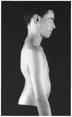
Fig. 8.1 Fifteen-year-old patient with severe spondylolisthesis at L5-S1 and pathologic lordosis.
Examination with the Patient Standing
Have the patient undress down to his or her underwear for further inspection. The patient should stand as erect as possible with both legs fully extended. Observe the patient from behind, from the side, and from the front. The patient’ s arms should hang down relaxed at the sides. Table 8.14 lists important points for inspection. Palpation and range-of-motion tests can be integrated into the inspection phase of the examination. First, obtain a general impression of the patient’ s posture, musculature, and axial symmetry. Note the position of the hips, knees, and ankles. In extreme spondylolisthesis or spondyloptosis, extreme lordosis will be present; slender patients will show a step sign in the spinous processes (known as a “ski-jump” phenomenon; Fig. 8.1). Skin changes such as cafe-au-lait spots or neurofibromas can be clinical signs ofgeneralizedneurofibromatosis (vonReckling-hausen disease), a systemic disorder frequently associated with scoliosis (Figs. 8.2a, b). Localized hypertrichosis in the region of the spinous processes suggests failure of fusion of the vertebral arches (Fig. 8.3).
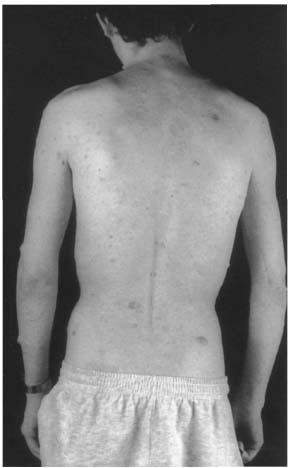
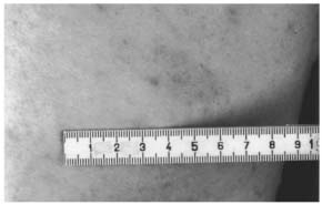
Figs. 8.2a, b Patient with generalized neurofibromatosis. Findings include multiple fibromas and several café-au-lait spots (a); café-au-lait spot in the same patient (b).
Inspection from behind may proceed from superior to inferior or in the opposite direction. The important point is to inspect systematically to minimize the risk of overlooking pathologic changes. Beginning from superior, note the posture of the head that is characteristically altered in torticollis. The course of the spinous processes provides further information; palpation permits more precise evaluation. Follow the spinous processes from the cervical spine into the thoracic spine. Significant deviation of the row of spinous processes from the midline of the coronal plane is usually due to severe scoliosis since the rotational component is only sufficient to shift the row of spinous processes away from the coronal midline in severe cases. The level of the shoulders and scapulae (Figs. 8.4 and 8.5) provides important information about scoliotic deformities. Shoulders should be level and the scapulae should blend smoothly and symmetrically into the posterior musculature. Peripheral neuropathy should be excluded as a possible cause of asymmetry in this region. Muscle contour should be symmetric on both sides; document any muscular atrophy or hypertrophy. The triangles at the waist, bounded by the arms hanging loosely at the patient’ s sides, should be symmetric. Asymmetric triangles at the waist are seen primarily in scoliosis and are an important clinical sign of an underlying deformity (Fig. 8.4). A vertical plumb line suspended from the spinous process of C7 should intersect the gluteal cleft in a balanced spine. Scoliosis should be excluded whenever the spine is seen to deviate from vertical (Fig. 8.6). Inspect the Michaelis rhomboid for symmetry. This figure is formed by the two iliac spines, the spinous process of L5, and the most proximal point of the gluteal cleft (Fig. 8.7).
Bending test. Instruct the patient to bend forward. Document the projection of the ribs and the lumbar bulge, both of which are important signs of scoliotic deformity of the spine. Rib projection is due to rotation of the ribs in an angular deformity frequently associated with scoliosis (Figs. 8.8–8.10). The lumbar bulge is caused by projection of the paravertebral musculature on one side as a result of the rotational deformity. A scoliometer can be used to clinically quantify the severity of the rotational deformity (Fig. 8.11).
Table 8.15 summarizes the range-of-motion tests described in the following section.
The results of this test should be compared to the degree of hip flexion achieved during manual motor testing of hip flexors. A discrepancy between formal and informal tests of lumbar spine motion suggests a nonanatomic cause for decreased motion.
Distance between fingers and floor. To test the range of motion of the spine, first instruct the patient to bend over as far as possible with the knees fully extended. Measure the distance between the patient’ s fingers and the floor (Fig. 8.12). Normally this should be 0-10 cm, but it may be greater without underlying pathology. The bending test can also be evaluated as a nerve-stretch test (Lasègue test with the patient standing); findings can be compared with the results
• Distance between fingersand floor • Otttest • Schober test • Neutral-zero method |
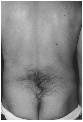
Fig. 8.3 Lumbosacral hypertrichosis
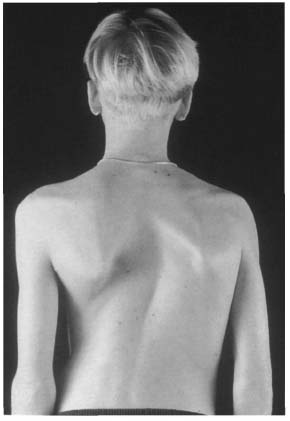
Fig. 8.4 Fourteen-year-old patient with idiopathic right convex thoracic scoliosis. Note the asymmetric level of the scapulae and the reduced triangle at the waist on the right side.
of the Lasègue test with the patient sitting and supine.
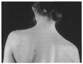
Fig. 8.5 Twenty-two-year-old patient with right convex thoracic scoliosis and a high thoracic left convex countercurvature that lowers the level of the right shoulder.
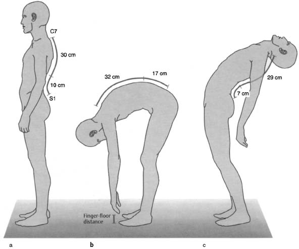
Ott and Schober signs. Next, check for the Ott and Schober signs. Locate the most prominent spinous process (C7). Measure 30 cm caudal to this landmark and mark the site. Note any changes in the length of this line that occur as the patient bends forward and backward. Ott cites lengthening of 2–4 cm and shortening of 1 cm as normal.
To perform the Schober test, use S1 as the starting point for measuring a line extending 10 cm craniad. Document changes in the length of this line as the patient bends forward and backward as far as possible. Normal values for this test are 4–7 cm of lengthening and 3 cm of shortening (Figs. 8.13a-c). The thoracolumbar spine can be further evaluated by defining a 10 cm line with its midpoint at L1 and measuring the changes in length as the patient bends forward and backward.
Neutral-zero method. The neutral-zero method permits a more precise measurement of the range of motion of the spine in all three planes. Measurements are performed with the patient standing or sitting (see Table 8.19 for normal values).
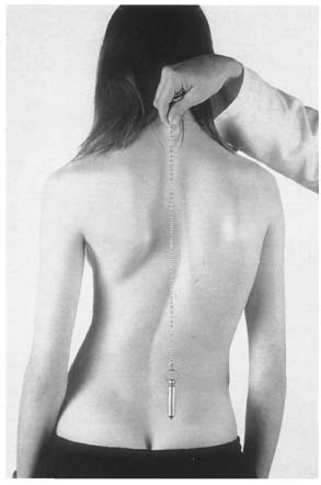
Fig. 8.6 Fifteen-year-old patient with idiopathic right convex thoracic scoliosis in a long arc, deviating from vertical to the right.
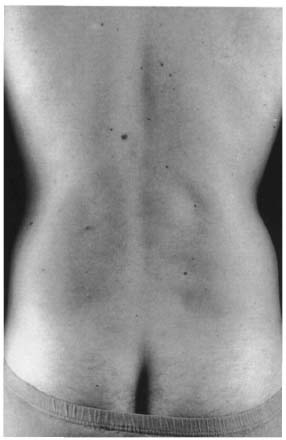
Fig. 8.7 Symmetric Michaelis rhomboid.
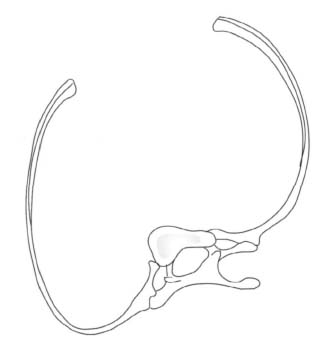
Fig. 8.8 Diagram of a rib with an angular deformity. The rotation of the vertebra in thoracic scoliosis raises the rib and causes it to project when the patient bends over.
Isolated pelvic obliquity without a rotational component is a reliable sign of a leg-length difference (Lewit 1977) (Fig. 8.14). To obtain a more accurate measurement of the leg-length difference, place standardized measuring plates under the shorter leg until the pelvis is level. Precise evaluation of the leg length and axis deviation requires radiographic measurements.
Pelvic obliquity can occur without a difference in leg length. In these cases, it is usually accompanied by a rotational deformity of the pelvis. This is recognized by the asymmetric position of the iliac spines. Scoliosis is a frequent cause of pelvic rotation of this type (Fig. 8.15). Table 8.16 lists important landmarks for palpation of the spine and pelvis.
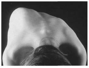
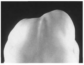
Fig. 8.10 Posterior view of the same patient as in Fig. 8.9.
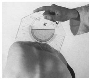
Fig. 8.11 Projection of the ribs is measured in degrees using a scoliometer placed at the level of maximum projection.
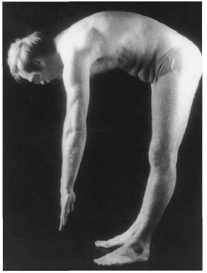
Fig. 8.12 The distance between the patient’ s fingers and the floor is measured to evaluate the range of motion of the spine.
• Spinous process • Iliac crest • Anterior inferior iliac spine • Anterior superior iliac spine • Sacroiliac joint • Greater trochanter |
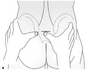
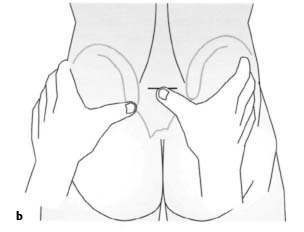
• Pathologic anterior movement of the posterior iliac spines
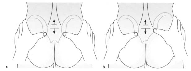
Next locate the posterior iliac spines and instruct the patient to forward flex again. Observe whether the iliac spines move anteriorly. This is a sign of limited motion in the sacroiliac joints. If motion in the sacroiliac joints is limited, the posterior superior iliac spine on the affected side will move superiorly (Figs. 8.16a, b). Pathologic anterior movement of the posterior iliac spine can be tested with the patient supine (Figs. 8.17a, b) if there is a difference in leg length.
Spine test. This is a further test for examining the sacroiliac joints. Locate the posterior superior iliac spine on one side with your thumb. Mark the position of the median sacral crest at the same level with your other thumb. Then instruct the patient to lift the leg on the palpated side. Normally the iliac spine will dip as a result of the motion of the sacroiliac joint. If the sacroiliac joint is impaired, compensatory tilting of the pelvis will cause the iliac spine to move superiorly (Figs. 8.18a, b).
Trendelenburg sign. Instruct the patient to stand on one leg to evaluate the pelvic and trochanteric musculature (gluteus médias and minimus). Pelvic version in the coronal plane can be evaluated at the same time. If muscular weakness results in poor stabilization of the pelvis, a positive Trendelenburg sign will be present: the pelvis will dip toward the side of the flexed leg (Figs. 8.19a, b).
Next, inspect the standing patient from the side. This will reveal posture and structural changes such as thoracic hyperkyphosis (Figs. 8.20 and 8.21) or gibbus. Thoracic hyperkyphosis can occur in combination with lumbar hyperlordosis. However, this is more difficult to detect by inspection because of the thicker mantle of soft tissue covering the lumbar spine. Spondylolisthesis appears as a step sign; the severe forms produce what is known as a “ski-jump” phenomenon (see Fig. 8.1). Normally, the spine forms a slightly curved double S profile with kyphotic curves in the spine and sacrum and lordotic curves in the cervical and lumbar spine.
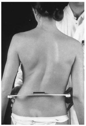
Fig. 8.14 Genuine leg-length difference in a scoliosis patient that manifests itself in pelvic obliquity with a left tilt. The measurement is made with a pelvic scale.
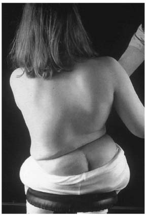
Fig. 8.15 Severe pelvic obliquity in a patient with neuromuscular left convex lumbar scoliosis; the cause is pelvic version resulting from an underlying spinal deformity.
Postures are categorized as lumbar hyperlordosis, thoracic hyperkyphosis, thoracic hyperkyphosis and lumbar hyperlordosis in combination, and flat back (Figs. 8.22a-f).
Inspection from anterior completes this phase of clinical examination. This reveals facial asymmetry as can occur in muscular torticollis, deformities of the rib cage, or deformities such as the transverse folds in the abdominal wall that are often present in thoracic hyperkyphosis (Table 8.17). Inspection of the anterior musculature is important in conjunction with pelvic obliquity and lumbar hyperlordosis. The axis of vision is clinically relevant in ankylosing spondylitis (Bechterew disease) in particular. Kyphotic stiffening of the entire spine, including the cervical spine, means that the patient can no longer see straight; a horizontal visual axis can no longer be achieved.
• Axis ofvision • Facial asymmetry • Rib cage deformities • Transverse abdominal folds |
After inspection is completed, test the range of motion of the cervical spine and measure the distance between the chin and sternum. This should measure 0 cm with the cervical spine in flexion, and approximately 20 cm with the cervical spine in maximum extension. The range of motion may be reassessed with the patient sitting.
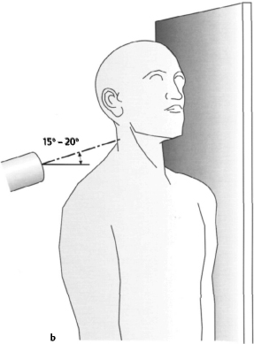
In ankylosing spondylitis measure also the distance between the external occipital protuberance and the wall, with the patient’ s heels touching the wall. This distance should normally be 0 cm and is typically higher in ankylosing spondylitis (Fig. 8.23). This measurement should allow for possible hip contractures that often accompany the disorder, possibly also contributing to the deviation of the torso. Finally, measure the excursion of the rib cage during respiration at the level of the nipples. Normally, this is 5-10 cm in young adults. In ankylosing spondylitis, it can be reduced at an early age (Table 8.18).
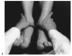
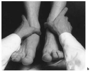
Figs. 8.17 , b Changing length of the right leg is observed with dysfunction of the right sacroiliac joint. As the patient sits up with the legs extended (b), asymmetric superior motion of the right medial malleolus is observed relative to findings with the patient supine (a). This is a sign of impaired motion in the right sacroiliac joint.
Figs. 8.18a, b In a normal spine test, the motion of the sacroiliac joint as the ipsilateral hip is flexed causes the iliac spine to dip.
• Axis of vision • Distance between external occipital protuberance and wall • Chest excursion during respiration • Hip contractures • Spinal curvature |
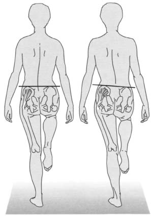
Figs. 8.19a, b Schematic diagram of a positive Trendelenburg sign.
Examination with the Patient Sitting
The rest of the examination is performed with the patient sitting. Normal values of the cervical spine are approximately 45°–50° for lateral bending, and 80° for rotation from a neutral position. The cervical spine is the most mobile segment of the spinal column. Only its lateral bending is limited to any great extent, primarily by the uncinate processes.
Where extension of the cervical spine is reduced, instruct the patient to repeat the test with the mouth open to relax the anterior musculature of the neck. If the patient then achieves greater extension, shortening of the musculature is responsible for the limited motion.
The thoracic spine is the least mobile segment of the spinal column. This is due to its articulations with the rib cage. Only the lower thoracic spine is somewhat more mobile because of the floating lower ribs. Extension is greatly limited due to the shingle-like arrangement of the articular processes.
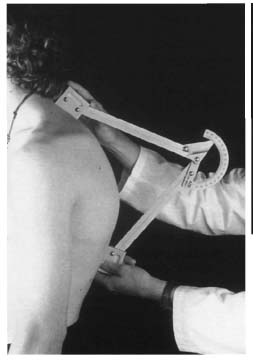
Fig. 8.20 Eighteen-year-old patient with thoracic hyperkyphosis in Scheuermann disease. The severity of the kyphosis can be measured in degrees during clinical examination using a kyphometer.
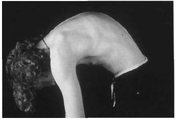
Fig. 8.21 The same patient as in Fig. 8.20. The kyphotic deformity is even more apparent when the patient bends over.
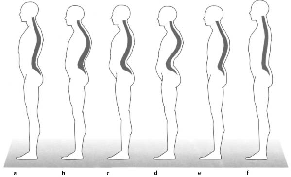
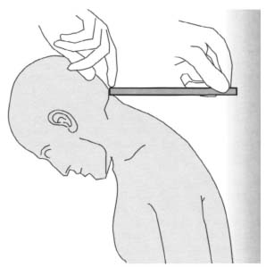
Fig. 8.23 Measurement of the distance between the occipital bone and the wall with the patient standing erect.
The lumbar spine has a relatively large range of motion in the sagittal and coronal planes but limited rotation due to the sagittal orientation of the facet joints. Rotation in the cervical and thoracic spines is about 30° in both directions. Next measure the range of lateral bending toward both sides. Normal values are 20°-40° (Table 8.19).
Examination with the Patient Lying Down
• Examination with the patient prone
The patient is prone for the next part of the examination. First palpate the spinous processes, beginning proximally. The first palpable spinous process is usually the second cervical vertebra. C7 can readily be localized because of its prominence and the fact that the spinous process of C6 disappears next to C7 as the patient extends the cervical spine. The iliac crests are other important landmarks that are usually at the same level as the spinous process of the fourth lumbar vertebra. Palpation of the row of spinous processes helps to detect common sites of pain, axial deviations, failure of fusion of the vertebral arches, and step signs in spondylolisthesis. The interspinous ligaments should also be examined for painful sites. Comparative palpation of the paravertebral musculature on both sides can reveal differences in tone indicative of segmental dysfunction.
| Cervical spine | Thoracic and lumbar spine | ||
| Flexion/extension | 50/0/70 | Flexion/extension | 120-130/0/20-30 |
| Lateral bending | 45/0/45 | Lateral bending | 20-40/0/20-40 |
| Rotation (in neutral position) | 80/0/80 | Rotation | 30/0/30 |
| Rotation (flexion) | 45/0/45 | ||
| Rotation (extension) | 60/0/60 |
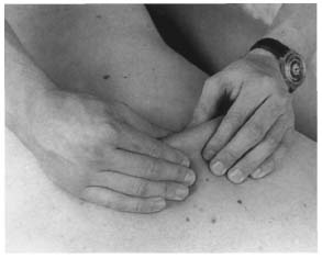
Fig. 8.24 Kibler fold in the region of the thoracic spine.
Palpate the iliolumbar ligaments at the point where the spine joint the pelvis. These ligaments originate on the transverse processes of the fifth lumbar vertebra and extend to the medial aspect of the iliac crest. Continue by palpating the sacrum and sacroiliac joints. The sacrospinal and sacrotuberal ligaments and the clinically significant piriformis will be palpable in the deep plane in slender patients. The relaxed gluteal musculature permits palpation of the ischial tuberosities and the hamstrings that originate there. The adductor magnus is also palpable. Rectal palpation of the coccyx may be necessary to evaluate coccygodynia injury following a fall on the buttocks (see Fig. 9.12, p. 428).
Kibler fold. Examine the paravertebral musculature for spasm. Placing the cervical spine in extension relaxes the muscle fascia and facilitates palpation. To localize muscle tension, grasp a fold of skin adjacent to the spine with the thumb and index finger and displace it superiorly (Fig. 8.24). An experienced examiner can determine differences in muscle tone by locally reduced suppleness that may be painful.
Springing test. This test may be used to examine joint play and tenderness in the individual segments. Place your index and middle fingers on the vertebral arch or the inferior articular processes and test the segment by applying slight pressure to the fingers with the ulnar edge of the other hand (Fig. 8.25).
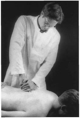
Fig. 8.25 Springing test in segmental examination of the thoracic spine.
Reversed Lasègue sign. You can test for the reversed Lasegue sign with the patient prone (Fig. 8.26). Passively hyperextend the leg at the hip while flexing the knee to apply an additional stretching stimulus. Radiating pain on the anterior thigh can suggest a nerve root irritation syndrome at L3-L4 (stretching pain in the femoral nerve) or shortening of the rectus femoris or iliopsoas. With nerve-root irritation syndromes, it is essential to compare both sides.
Mennel’ s first sign. This sign is elicited by a stress test of the sacroiliac joint performed with the patient prone. Immobilize the pelvis on one side by applying pressure to the sacrum and placing the ipsilateral hip in hyperextension. The sign is positive if the patient feels pain in the sacroiliac joint (Fig. 8.27). The test for Mennel’s second sign is performed with the patient supine (Fig. 8.28).
Three-step test. This test is performed to differentiate symptoms in the lumbar spine, sacroiliac joint, and hip. In contrast to the test for Mennell’ s first sign, begin by immobilizing the superior lumbar spine while placing the ipsilateral hip in hyperextension. This places stress on the inferior facet joints of the lumbar (first step). The second step is the same as in testing for Mennell’ s first sign, although your immobilizing hand now only stabilizes the sacrum to place stress on the sacroiliac joint. In the third step, evaluate irritation in the ipsilateral hip by moving your hand further inferior to immobilize the pelvis in the acetabular region while placing stress on the hip by hyperextending the leg.
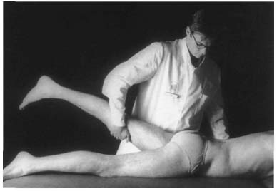
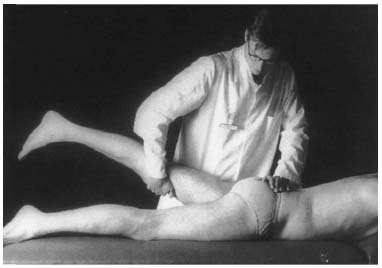
Fig. 8.27 Mennell’ s first sign. Immobilize the sacrum with one hand while placing the ipsilateral hip in hyperextension with the other.
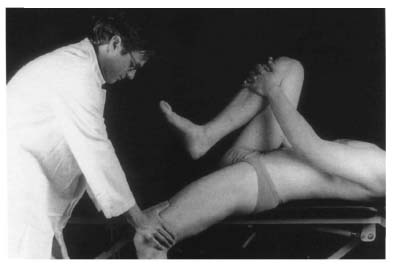
Fig. 8.28 Mennell’ s second sign. This test places stress on the left sacroiliac joint.
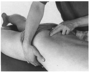
Fig. 8.29 Shaking test of the right sacroiliac joint.
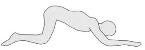
Fig. 8.30 Kneeling test for evaluating the flexibility of kyphotic deformities.
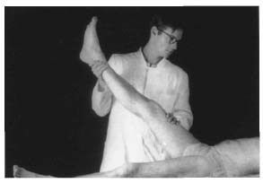
Fig. 8.31 Lasègue sign
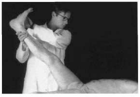
Fig. 8.32 Bragard sign
Shaking test. Palpate the sacroiliac joint inferomedial to the posterior superior iliac spine. With your other hand, grasp the wing of the contralateral ilium at the level of the anterior superior iliac spine. Now apply slight posterior shaking motions (Fig. 8.29). Where there is normal joint play in the sacroiliac joints, you will be able to feel fine movements with your palpating hand. Lack of, or limited motion in comparison to the contralateral side suggests hypomobility.
Valleix points. Deep palpation can subject the sciatic nerve to direct pressure between the ischial tuberosity and greater trochanter. Additional Valleix points are located along the course of the sciatic nerve on the posterior thigh. An irritated nerve will react with increased tenderness to palpation.
Kneeling test. This final test may be used to evaluate the flexibility of kyphotic deformities. Instruct the patient to assume a kneeling position and to attempt to stretch out on the examining table or floor with the arms extended as far as possible (Fig. 8.30).
• Examination with the patient supine
The patient is supine for the next part of the examination. It can be difficult to distinguish pseudoradicular pain from radicular pain. For example, irritation of the lumbar roots of the sciatic nerve from a prolapsed disk can elicit the nerve stretching sign.
Lasègue sign. With the Lasègue sign, passively lifting the extended leg 60° or less elicits pain extension from the low back into the calf or foot (Fig. 8.31).
It is important to distinguish this from a false Lasègue sign that involves pain radiating only as far as the knee due to stretching of the hamstrings. As a result of the one-sided pelvic version, pain with a Lasègue sign can also be a function of sacroiliac joint disease. In this case, differential diagnosis is made by repeating the test with both hips flexed and the legs extended; this eliminates the twisting of the pelvis so that the test will be negative if isolated dysfunction of the sacroiliac joint is present.
Bragard sign. The Lasègue sign can be intensified by passive dorsiflexion of the foot Fig. 8.32). Document the degree of hip flexion that causes pain.
Sit-up with legs extended. A final version of the test for the Lasègue sign should be performed by instructing the patient to sit up with the legs extended. This test and previous findings with the patient standing should be considered when evaluating the Lasègue sign to eliminate the possibility that the patient may be simulating symptoms.
Figs. 8.33a, b In the reclining test, nerve root irritation when expanding the leg will cause the patient to move backward in compensation (b).
Kernig sign. A different version of the Lasègue sign is the Kernig sign. This produces the same pain when the knee is passively extended with the hip flexed 90°. The same test can be performed with the patient sitting by having the patient extend the knee. This so-called reclining test is positive if the patient’ s torso moves backward (Figs. 8.33a, b). The various nerve-stretch signs are listed in Table 8.20.
An important differential diagnosis with back and leg pain is piriformis syndrome. In this syndrome, the piriformis is tender to palpation with noticeable pain in internal rotation (stretching) or painful external rotation and abduction against resistance (contraction) in the affected hip.
Patrick four-part sign. The Patrick test may be performed to further evaluate sacroiliac joint dysfunction that can simulate S1 nerve root irritation symptoms. The patient’ s leg is extended and the pelvis is immobilized on the examining table by applying pressure to the anterior superior iliac spine to eliminate pelvic motion. Flex the patient’ s other knee and abduct the other hip, keeping the foot of the leg supported by the contralateral knee (Fig. 8.34). Normally the knee of the abducted sign will reach the examining table. However, comparison of both sides is more important. Difference in mobility between the two sides with painfully restricted hyperabduction suggest dysfunction in the ipsilateral sacroiliac joints if hip disorders can be excluded and if the adductors are normal. Hip disorders can be eliminated by evaluating the range of motion of the hip (particularly rotation) and palpating the capsule of the hip in the deep plane of the groin. Other signs of a hip disorder include tenderness of the trochanter to palpation and pain upon axial compression.
• Lasègue sign • Bragard sign • Sit-up with legs extended • Reclining test • Kernig sign • Reversed Lasègue sign |
Mennell’ s second sign. Mennel signs are also regarded as tests that place stress on the sacroiliac joint. Compared to Mennel’ s first sign with the patient prone, the pelvis can be more effectively immobilized with the patient supine and the contralateral knee and hip in maximum flexion (Thomas grip). At the same time, the affected hip is hyperextended past the edge of the examining table, which places stress on the sacroiliac joint. Mennell’ s second sign is positive if pain is elicited in the region of the sacroiliac joint (Fig. 8.28).
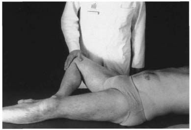
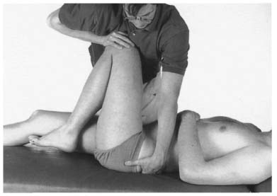
Fig. 8.35 Elasticity test of the left sacroiliac joint.
Elasticity test of the sacroiliac joint (including femur). To directly test the play in the sacroiliac joint, flex the contralateral knee and hip with the patient supine. Adduct the leg toward you until the pelvis begins to follow (the other leg remains extended). Next, grasp the knee of the adducted side and briefly apply elastic axial pressure to the knee while palpating the sacroiliac joint with the other hand. Normally this will produce elastic motion in the sacroiliac joint that will be palpable as relative motion between the posterior iliac spine and sacrum (Fig. 8.35). Lack of joint play in this test is typical of joint dysfunction (Eder and Tilscher 1995). This elasticity test is based on the principle that the range of motion of any intact joint can be increased, even when the joint is at the end of its range of motion, by applying elastic pressure. In principle, this type of test can be used to manually diagnose dysfunction in any joint. However, it is important to place stress on the joint before performing the test (Lewit 1977).
Changing leg length (Figs. 8.17 a, b, p. 301). The variant of the test for pathologic anterior movement of the posterior iliac spines can be performed with the patient supine. The length of both legs is evaluated using the medial malleoli as reference points as the patient sits up from a supine position. Loss or limitation of movement in the sacroiliac joint will produce a relative increase in leg length on the affected side. Table 8.21 summarizes the individual stress tests of the sacroiliac joint.
• Examination with the patient in a lateral position
Segmental range-of-motion testing in the lumbar spine is performed with the patient in a lateral position with both hips and knees flexed. Stand facing the patient, grasping both calves with one hand. The patient’ s legs may rest on your thighs to give you more information about the respective motion. With your free hand, palpate two adjacent spinous processes and the respective interspinal space. Successively test each segment in flexion, extension, and in a neutral position by passively moving the lower extremities. The same examining technique can be used to detect a limited range of motion in lateral bending. Evaluate lateral bending by lifting and lowering the patient’ s calves (Fig. 8.36). Locally limited or increased mobility, indicative of segmental dysfunction, is regarded as pathologic.
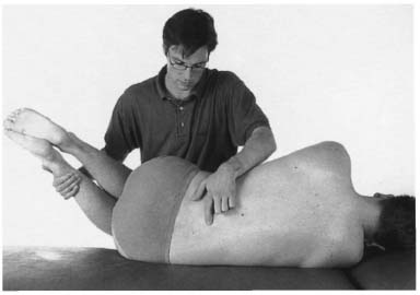
Fig. 8.36 Segmental range-of-motion testing of the lumbar spine (lateral bending) with the patient in a lateral position.
Neurologic Examination
Neurologic examination of the spine includes the upper and lower extremities and the torso. Initially this entails testing muscles, sensation, reflexes, and coordination, including relevant autonomous functions.
Motor deficiencies involving paralysis are categorized as flaccid or spastic paralysis. The former occurs when the lower motor neuron is damaged or in spinal shock; the latter occurs as a result of a lesion of the upper motor neuron. This can be demonstrated by what is known as the jackknife phenomenon in which increased muscle tone is suddenly overcome after maximum muscle extension. Other clinical signs include the so-called pyramidal tract signs that are discussed in the individual sections.
• Mennell’ s first sign • Mennell’ s second sign • Elasticity test including femur • Shaking test • Test for pathologic anterior movement of the posterior • Changing leg length • Spine test • Patrick four-part sign • Three-step test |
Neurologic Examination of the Upper Extremities
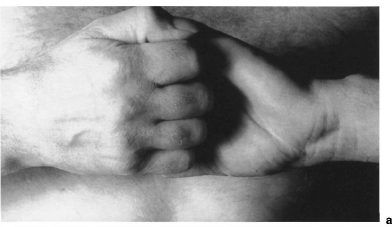
Neurologic examination of the upper extremities may begin by having the patient clasp the hands behind the head and behind the back (Figs. 8.37 and 8.38). This will give you a rough overview of the patient’ s capacity for abduction, external or internal rotation in the shoulder, and flexion in the elbow. Joint diseases should be distinguished from neurologic deficits.
Detailed examination of muscle strength involves testing the strength of individual muscle groups with the patient sitting. Elbow flexion against your resistance can be used to test segments C5 and C6. Segment C7 and C8 are tested by evaluating elbow extension. Muscle strength is graded on a scale of 0 (no palpable contractility) to 5 (normal muscle strength) as shown in Table 8.22. Latent paralysis of the upper examination can be tested by instructing the patient to extend both arms in supination with the eyes closed (arm-extension test). Pronation and subsequent lowering of one arm suggest a latent central hemiparesis. An arm that drops before the hand moves into pronation while the patient’ s eyes are closed may be attributable to psychogenic influence (Figs. 8.39a,b).
Sensory supply to the upper extremities is divided into band-shaped dermatomes (Figs. 8.40a,b).
The important intrinsic muscle reflexes of the upper extremity include the biceps and brachioradialis reflexes (C5 and C6), the triceps reflex (C7), and Trömner reflex (C8) that involves tapping the patient’ s fingertips to elicit reflexive flexion of the distal phalanges including the thumb (Figs. 8.41–8.44). The Trömner and snap reflexes are both intrinsic reflexes of the flexors of the fingers. If they can be elicited on both sides, they only indicate a greater sensitivity to reflex stimuli; unilateral response is regarded as a pyramidal tract sign. Table 8.23 summarizes the individual intrinsic muscle reflexes and the respective muscles involved.
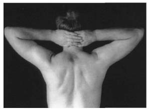
Fig. 8.37 Clasping the hands behind the head.
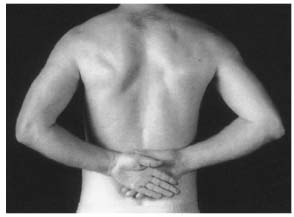
Fig. 8.38 Clasping the hands behind the back.
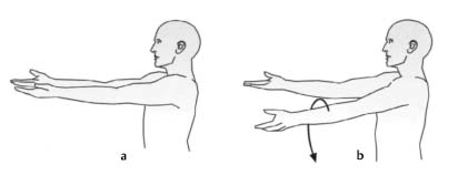
Figs. 8.39a, b Arm extension test for evaluating latent central hemiparesis characterized by pronation and subsequent lowering of the affected arm.
| Muscle gradation | Muscle reaction |
| 0 | No palpable contractility |
| 1 | Evidence of slight contractility, but insufficient to move the extremity with gravity eliminated |
| 2 | The muscle is able to move the extremity with gravity eliminated |
| 3 | The muscle is able to move the extremity against gravity |
| 4 | The muscle moves the extremity against some resistance |
| 5 | Normal muscle strength against resistance |
| Nerve root | Intrinsic muscle reflex | Muscles involved |
| C5 | Biceps reflex | Deltoid, biceps |
| C6 | Brachioradialis reflex | Biceps, brachioradialis |
| C7 | Triceps reflex | Triceps, thenar eminence |
| C8 | Trömner reflex | Flexors of the fingers, hypothenar eminence |
According to Kramer (1994) most monoradicular cervicobrachial syndromes involve the intervertebral disk C5-C6, affecting nerve root C6 (C6 syndrome). This is followed by intervertebral disk spaces C6-C7 and C7-T1 with the associated C7 and C8 syndromes. Table 8.24 shows the incidence of nerve-root involvement in monoradicular cervicobrachial syndrome.
For a preliminary test of coordination, instruct the patient to close his or her eyes and to touch the nose with the index finger in a long sweeping motion. Another coordination test is the diadochokinesis test in which the patient alternately performs supination and pronation motions, as if screwing in a lightbulb.
| Affected nerve root | Incidence |
| C5 | 4.1% |
| C6 | 36.1% |
| C7 | 34.6% |
| C8 | 25.2% |
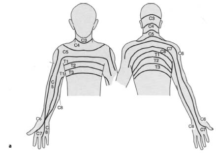
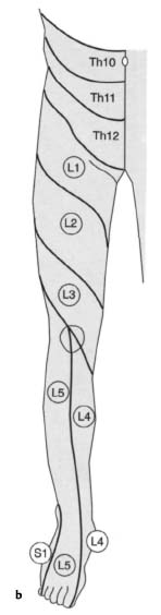
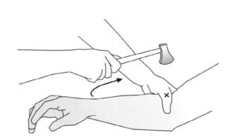
Fig. 8.41 Biceps reflex
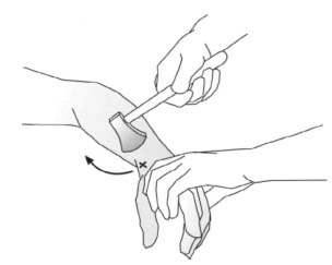
Fig. 8.42 Brachioradialis reflex
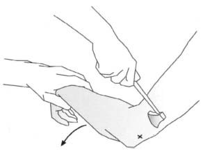
Fig. 8.43 Triceps reflex
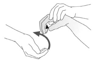
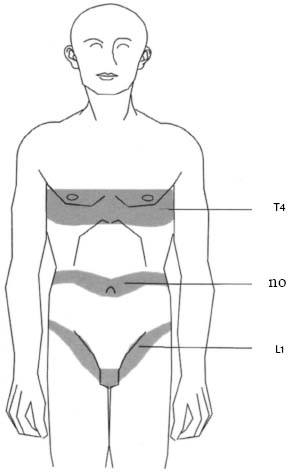
Fig. 8.45 Anatomical landmarks on the surface of the torso for determining the level of transverse paralysis.
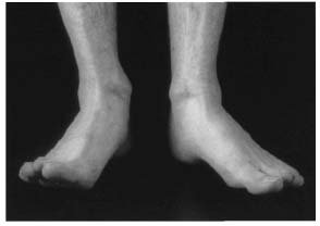
Fig. 8.46 Heel position with weakness of the extensors of the left great toe in a prolapsed disk at L4–L5.
Neurologic Examination of the Surface of the Torso
Neurologic examination of the surface of the torso is useful primarily in determining the level of transverse lesions. Note that the cord usually ends at the level of L1 or L2 where it joins the cauda equina. From about T1 on, the segments are shifted superiorly because of the early cessation of growth of the spinal cord so that segment T12 lies at about the level of the ninth thoracic vertebra. The sacral segments begin at about the 11th or 12th thoracic vertebra.
Only the spinal groups between C8 and L2 have sympathetic fibers so that sympathetic deficiencies such as disturbed sweat secretion should not be expected in injuries below the 10th thoracic vertebra. The nipples (T4–T5), umbilicus (T10), and the groin (L1) are helpful anatomic landmarks on the torso (Fig. 8.45). Transverse lesions superior to the fourth cervical vertebra results in loss of function in the phrenic nerve that produces bilateral paralysis of the diaphragm and respiratory insufficiency.
The superficial abdominal reflexes are physiologic reflexes that may be used to evaluate segments T6 through T12. These reflexes are tested by rapidly moving a needle across the skin from lateral to medial at the level of the inferior costal arch and umbilicus, and superior to the inguinal ligament. A polysynaptic reflex arc produces contraction of the abdominal musculature.
Neurologic Examination of the Lower Extremities
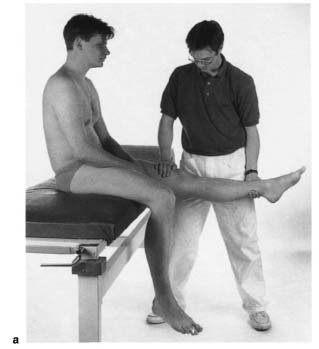
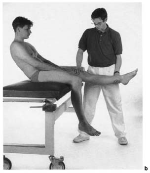
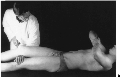
Neurologic examination of the lower extremities in patients capable of standing and walking begins by observing their gait. Instruct the patient to stand and walk on tiptoe and on the heels (Fig. 8.46). This is usually performed to exclude major motor deficiencies. With the patient supine, evaluate the strength of the quadriceps in knee extension (L3–L4), the extensor digitorum and hallucis longus in dorsiflexion of the toes (L5), and the triceps surae in plantar flexion of the foot (S1). The patient should perform these motions against your resistance. Where there are negative findings, exclude latent central hemiparesis in the leg holding test. Instruct the patient to close his or her eyes and flex both hips and knees at right angles. Lowering of the calf is a sign of latent central hemiparesis (Fig. 8.47).
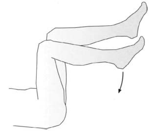
Fig. 8.47 Leg-holding test to detect latent hemiparesis of the lower extremities.
Sensory supply to the torso and lower extremities is divided into band-shaped dermatomes (Figs. 8.40a, b). The most important areas of sensory supply are in order of their clinical significance in nerve-root irritation syndromes: 1 segment S1 that extends in a posterolateral strip from the buttock to the lateral margin of the foot; 2 the region supplied by segment L5 extending from lateral and passing slightly inferior to the patella and across the lateral malleolus into the great toe; 3 segment L4 with its dermatome extending from the thigh across the knee to the medial malleolus. A prolapsed disk between L5 and S1 can affect nerve roots L5 and S1. In a mediolaterally prolapsed disk, the inferior root is affected (in this case S1); a laterally prolapsed disk affects the superior root (in this case L5). Combined compression of both nerve roots can also occur.
The perianal region receives its sensory supply from segments S3–S5 and is important in cauda equina syndrome. In these cases, what is known as “saddle anesthesia” typically occurs due to loss of sensory supply from segments S3–S5, with disturbed micturition, defecation, and sexual function (Fig. 8.48). The tone of the anal sphincter in such cases is reduced and clinically significant. It can be evaluated by instructing the patient to close it around your palpating finger during rectal examination. Other clinical signs of cauda equina syndrome include lack of anal and bulbocavernosus reflexes that present as extrinsic differences of segments S3–S5 (Masuhr and Neumann 1992; Table 8.27). With a medially prolapsed disk, partial flaccid paralysis will often be present with radicular loss of sensation.
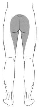
Fig. 8.48 “Saddle anesthesia” with loss of sensation in dermatomes S3–S5.
The next phase of the examination involves testing reflexes. Table 8.25 lists the respective muscles tested with their segments. The two most important intrinsic muscle reflexes in the lower extremities are the patellar reflex (L3–L4) and the Achilles tendon reflex (S1–S2). Other intrinsic muscle reflexes include the tibialis posterior reflex (L5), elicited by tapping the tibialis posterior tendon superior of inferior to the medial malleolus, and the adductor reflex (L3–L4), which can be elicited by tapping the medial femoral condyle (Figs. 8.49–8.52). The adductor reflex is difficult to elicit. Since the patellar reflex tests the same segment, it can be used instead. If reflex response is weak, the Jendrassik maneuver (Figs. 8.53a, b) can be used to emphasize the patellar reflex and facilitate evaluation.
| Nerve root | Intrinsic muscle reflex | Muscles involved |
| L3 | Adductor reflex, patellar reflex | Hip adductors, quadric ceps femoris |
| L4 | patellar reflex | Quadriceps femoris, tibialis anterior |
| L5 | Tibialis posterior reflex | Extensor hallucis, tibi alis anterior |
| S1 | Achilles tendon reflex | Triceps surae, gluteus maximus |
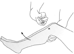
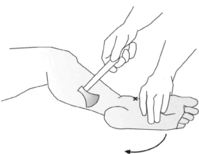
Fig. 8.50 Achilles tendon reflex.
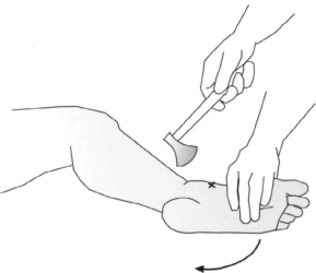
Fig. 8.51 Tibialis posterior reflex.
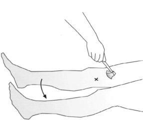
Fig. 8.52 Adductor reflex
If a lumbar nerve root is irritated or injured, monoradicular lumbar syndrome will result. 98% of the time the L5–S1 or L4–L5 segments are affected (Krämer 1994). The rest is distributed among the proximal lumbar segments (Table 8.26).
However, a purely monoradicular syndrome is present in only about half of all cases. Often several nerve roots are affected simultaneously. For example, a prolapsed disk in the most distal segment of a fivesegment lumbar spine can compress both the nerve roots L5 and, laterally, S1 (Fig. 8.54). A far lateral disk prolapse at this level can also produce only an L5 syndrome. However, a mediolateral prolapse with predominantly S1 symptoms is frequent.
| Affected nerve root | Incidence |
| L2 | 0.5% |
| L3 | 0.5% |
| L4 | 1.0% |
| L5 | 43.8% |
| S1 | 54.2% |
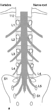
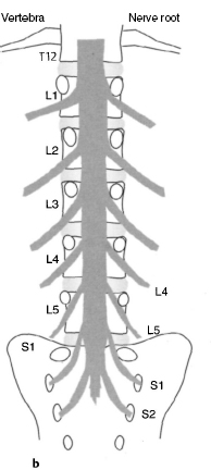
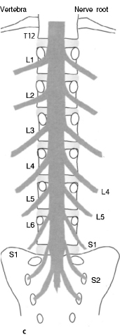
Numerous variations of the lumbar spine can make neurologic diagnosis difficult. For example, in a four-segment lumbar spine, the nerve root L5 courses through the first sacral foramen. In a six-segment lumbar spine, the nerve root S2 courses through this foramen (Figs. 8.55a–c).
The physiologic superficial reflexes are polysynaptic and exhaustible proprioceptive reflexes, in contrast to the monosynaptic intrinsic muscle reflexes. These include the cremasteric reflex in which contraction of the cremaster may be elicited by stroking the medial side of the upper thigh (L1–L2), the bulbo-cavernosus reflex in which contraction of the bulbo-cavernosus is elicited by stroking the dorsum of the penis, and the anal reflex in which stroking of the perianal region causes contraction of the anal sphincter (S3–S5) (Table 8.27).
Figs. 8.53a, b Jendrassik maneuver (a) applied when eliciting the patellar reflex (b).
The physiologic superficial reflexes require central stimulation and are weakened or absent when the upper motor neuron is damaged. Subsequently, flaccid paralysis will develop into spastic paralysis with increased intrinsic muscle reflexes due to the lack of inhibition from central efferents. The severity of the spastic paralysis will increase, the higher the neurologic level of injury. Where the lower motor neuron is damaged, both intrinsic muscle reflexes and superficial reflexes will be absent.
After this examination, test for pathologic reflexes (pyramidal tract signs). These signs are positive if injury to the upper motor neuron, the pyramidal tract, is present. They can be elicited by stroking the lateral sole of the foot (Babinski) or by pressing on the muscles of the calf (Gordon). Tonic dorsiflexion of the great toe with abduction of the other toes is characteristic.
| Physiologic reflex | Neurologic level |
| Cremasteric reflex | L1–L2 |
| Bulbocavernosus reflex | S3–S4 |
| Anal reflex | S3–S5 |
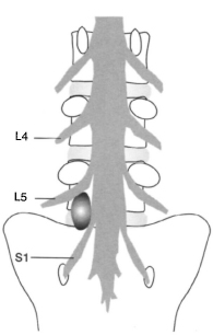
Fig. 8.54 A sufficiently severe laterally prolapsed disk at L5–S1 can compress nerve root L5 inside the foramen and nerve root S1 laterally.
A brief coordination test concludes examination. Instruct the patient to touch the patella with the contralateral heel with his or her eyes closed.
References
Castro WHM, Schilgen M. Kreuzschmerzen. Ursachen, Behandlung, Vorbeugung. Berlin-Heidelberg-New York: Springer; 1995
Castro WHM, Schilgen M, Meyer S, Weber M, Peuker C, WörtleK. Do “whiplash injuries” occur in low speed rear impacts. Eur Spine J. 1997; 6: 366–375.
Eder M, Tilscher H. Chirotherapie. Stuttgart: Hippokrates; 1995
Hoppenfeld S. Klinische Untersuchung der Wirbelsäule und der Extremitäten. Stuttgart-New York: Fischer; 1992
Krämer J. Kreuzschmerzen aus orthopädischer Sicht. Deutsches Ärzteblatt. 1994; 5: 227
Lewit K. Manuelle Medizin. 2nd ed. Munich-Vienna-Baltimore: Urban & Schwarzenberg; 1977
Ludolph E. Das Halswirbeltrauma nach geringer Belastung. In: Weber M, ed. Die Aufklärung des Kfz-Versicherungsbetruges – Grundlagen der Kompatibilitätsanalyse und Plausibilitä’tsprüfung. Schriftenreihe Unfallrekonstruktion. MS; 1995
Masuhr KF, Neumann M. Neurologie. Stuttgart: Hippokrates; 1992
Weber M, ed. Die Aufklärung des Kfz-Versicherungsbetruges – Grundlagen der Kompatibilitätsanalyse und Plausibi-litätsprüfung. Schriftenreihe Unfallrekonstruktion. MS; 1995
8.3 Radiology
Indications, Diagnostic Value, and Clinical Relevance
As in all other imaging of the musculoskeletal system, films taken in two planes at right angles to each other provide the basic studies for radiologic diagnosis of the spinal column. The AP and lateral projections of the spinal column can be taken with the patient supine or standing. In an AP radiograph with the patient supine, flexing the patient’ s hips during the exposure will compensate for physiologic curves of the spine. This will expose the intervertebral spaces although the radiograph will only show the bony details. If there are anomalies in the sagittal and coronal planes, a standing radiograph should be prepared. Full-length spine radiographs should always be prepared to allow sufficient evaluation of all secondary curves, the position of the pelvis, and deviations from vertical that may be present.
| Bone structure | ++ |
| Facet arthritis | +++ |
| Disk prolapse | − |
| Symptomatic disk without prolapse | − |
| Trauma | +++ |
| Spondylitis | ++ |
| Deformities | +++ |
| Tumor | +++ |
| Spinal stenosis (central) | + |
| Lateral stenosis | (+) |
− No information content
(+) Low information content
+ Moderate information content
++ High information content
+++ Very high information content
Certain situations will require additional special views such as the open-mouth odontoid view for diagnosing a dens fracture. Right and left oblique views are obtained to image the facet joints and the foramina for diagnosing spondylolysis. Flexion and extension views of the spine are used to diagnose instability or loss of motion in patients with back pain. Side bending views are used to assess curve flexibility.
Plain-film radiographs are of limited value in diagnosing soft-tissue conditions (Table 8.28). However, these conditions must be evaluated in patients with back pain or in the presence of injuries to the spinal cord. CT and MRI are valuable in such cases. Invasive studies such as myelography, and in rare cases discography, can provide important information.
Cervical Spine
Standard Views
AP view (Figs. 8.56 and 8.57). The AP radiograph may be taken with the patient standing or supine. The central ray is aimed at the fourth cervical vertebra (at the level of the Adam’ s apple) and angled cranially approximately 15°–20°. This projection provides good exposure of the cervical vertebrae C3–C7 (and in young patients often the atlas and axis as well), the uncovertebral joints (Luschka joints) with the uncinate process, and the disk spaces. The spinous processes are imaged almost head on and cast oval tearshaped shadows.
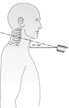
Fig. 8.56 In the AP radiograph of the cervical spine, the central ray is angled cranially, approximately 15°–20° from horizontal.
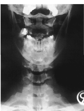
Fig. 8.57 Plain PA radiograph of the cervical spine. Normal findings in a 30-year-old female patient.
The atlas and axis are visualized by having the patient quickly open and close his or her mouth to obscure the mandible. This provides a good image of the first two cervical vertebrae.
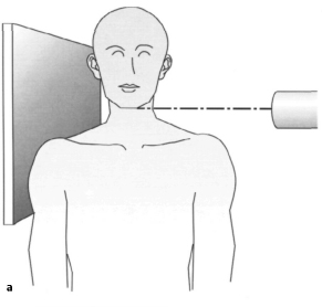
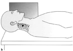
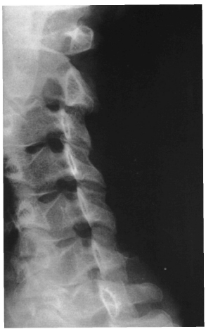
Lateral views (Figs. 8.58a,b and 8.59). The lateral radiograph may be taken with the patient supine, standing, or sitting. This view of the cervical spine is valuable because the important traumatic changes to the cervical spine are discernible. Visualized structures include the anterior and posterior arch of the atlas, the dens in profile, and the distance between atlas and dens. The vertebral bodies and the spinous processes are visible from C2–C7, and the disk spaces and prevertebral soft tissue can be evaluated. The central ray is aimed at the middle of the fourth cervical vertebra in this projection. The entire seventh cervical vertebra and the top plate of the first thoracic vertebra should be visualized on a lateral radiograph. Failure to do so could lead to missing a fracture (Figs. 8.82a,b, see p. 327).
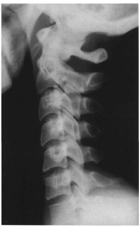
Fig. 8.59 Plain lateral radiograph of the cervical spine. The image shows normal findings.
The lateral radiograph of the cervical spine, including the base of the skull, is important to evaluate subsidence involving the atlantoaxial joint and migration of the dens to the foramen magnum. The extent of cranial displacement of the dens can be reliably determined using Chamberlain’ s line from the posterior margin of the foramen magnum, McGregor’ s line from the lowest point of the base of the occiput to the posterior margin of the hard palate, or McRae’ s line to the anterior margin of the foramen magnum (Figs. 8.60–8.62). Normally, the dens should not be more than 3 mm above Chamberlain’ s line, and no more than its tip should intersect McRae’ s line. The dens should not project more than 4.5 mm beyond McGregor’ s line. Since the hard palate is often difficult to define on the conventional lateral radiograph, Ranawat et al. (Greenspan, 1993) developed another method for measuring the superior protrusion of the dens. First, the coronal axis of the atlas is marked with a line. Next, the center of the anterior sclerosed ring of the axis is located and a line is drawn cranially, parallel to the axis of the dens. The distance to the point of intersection with the atlas line should average 17 mm in men and 15 mm in women (Fig. 8.63).
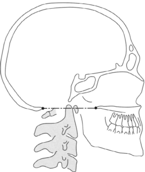
Fig. 8.60 Chamberlain’ s line extends from the posterior margin of the hard palate to the anterior margin of the occiput. The tip of the dens axis should normally not project to more than 3 mm above this line.
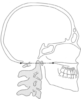
Fig. 8.61 McGregor’ s line extends from the posterior margin of the hard palate to the inferior margin of the occiput. The tip of the dens axis should normally not project to more than 4.5 mm above this line.
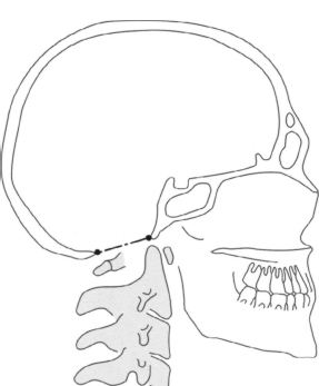
Fig. 8.62 McRae’ s line extends from the anterior margin of the foramen magnum to the anterior margin of the occiput. The tip of the dens axis should normally not project above this line.
Special Views
Open-mouth odontoid view (Figs. 8.64 and 8.65). To measure the dens axis, an AP radiograph is prepared with the patient’ s mouth open and the central ray aimed at the middle of the open mouth. The patient should say “ah” to avoid shadows from the tongue. This view provides good exposure of the cervical articular pillars (lateral masses) of the atlas, the entire axis with the dens, and the atlantoaxial joints with the lateral spaces. The Fuchs odontoid process position can be useful for better visualizing the tip of the dens in particular. In this position the cervical spine is overextended and the central ray is aimed slightly below the tip of the chin.
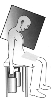
Oblique views (Figs. 8.66a, b and 8.67). These views are used for visualizing the intervertebral foramina. The actual oblique radiographs of the cervical spine are taken in an AP or PA projection with the patient sitting upright. The patient is turned 45° to one side of the room and the respective contralateral foramina are imaged in an AP projection. The central ray is aimed at the fourth cervical vertebra and is angled craniallyl5°-20°.
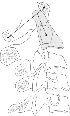
Fig. 8.63 Ranawat’ s method for measuring the protrusion of the dens axis. The coronal axis of the atlas is marked with a line; another line, parallel to the axis of the dens, is drawn cranially from the center of the anterior sclerosed ring of the axis. The distance to the point of intersection with the atlas line is then measured.
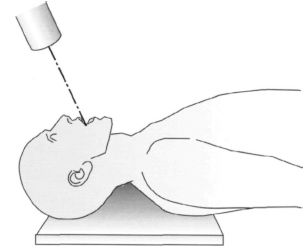
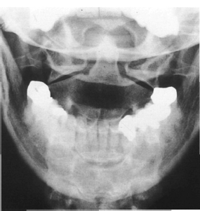
Fig. 8.65 Plain radiograph of an open-mouth odontoid view. The image shows normal findings.
Figs. 8.66a, b To image the facet joints and the intervertebral foramina of the cervical spine, the patient stands at an angle of approximately 45° to the X-ray beam. The beam is angled cranially, at approximately 15°–20°.
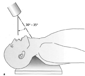
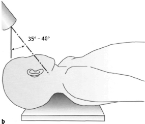
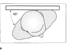
Figs. 8.68a, b The AP axial oblique position allows evaluation of the lateral masses. The patient is supine with the cervical spine overextended and the X-ray beam angled 30°–35° caudally toward the thyroid from vertical. It can also be prepared as an oblique projection by turning the patient’ s head 45°, aiming the central ray at a point 3 cm below the earlobe, and angling the tube 35°-40° caudally from vertical.
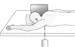
Fig. 8.69 The swimmer’ s view is used to image the cervico-thoracic region. The arm on the side of the film cassette is placed alongside the body. The arm on the side of the X-ray beam is abducted 180° and the beam is aimed at the axilla.
AP axial oblique position (Figs. 8.68a, b). This position permits visualization of the lateral masses of the cervical vertebrae (Greenspan 1993). The radiograph can be prepared with the patient supine and the neck overextended and the central ray aimed at the thyroid cartilage and angled 30°-35° caudally. It can also be prepared as an oblique projection of the lateral masses by turning the patient’ s head 45°, aiming the central ray at a point 3 cm below the earlobe, and angling the tube 35°-40° caudally.
Swimmer’ s position (Figs. 8.69 and 8.70). This position is used for visualizing vertebrae C7, Tl, and T2, which are often obscured by the clavicle and shoulder in conventional views. This view is prepared with the patient supine. The arm on the side of the film cassette is placed alongside the body. The contralateral arm is abducted 180°, and the X-ray beam is aimed at the axilla.
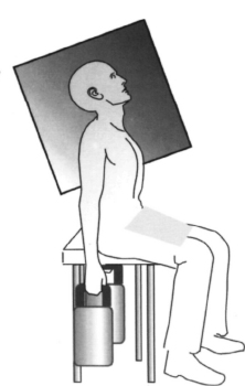
Figs. 8.71 a, b The flexion and extension views of the cervical spine can be obtained with the patient sitting. It is important to demonstrate the seventh cervical vertebra. It may be necessary to give the patient weights to hold to prevent the shoulders from obscuring the C7-T1 level. The X-ray beam is aimed at the center of the cervical spine as in the lateral projection.
Dynamic Views
These views should only be obtained after bony instability has been excluded. They are helpful in evaluation of the function of the cervical spine. Various methods are used to measure mobility.
Flexion and extension views are taken in a lateral projection. These are done with a fully conscious, cooperative patient without neurologic deficits. The patient is encouraged to obtain maximum voluntary flexion and extension. The study may be done with fluoroscopic visualization or plain films in maximum flexion and extension (Figs. 8.71 a, b and 8.72 a, b).
Dynamic views represent an important method for diagnosing atlantoaxial instability resulting from lesions of the transverse ligament of the atlas or the alar ligaments. They can be traumatic, inflammatory, or congenital in origin (os odontoideum). In the flexion radiograph, less than 3 mm between the anterior margin of the dens and the posterior margin of the anterior arch of the atlas is regarded as physiologic (Greenspan 1993). Values between 3 mm and 5 mm indicate a lesion of the transverse ligament of the atlas, and values between 5-8 mm suggest the presence of an additional lesion of the alar ligaments.
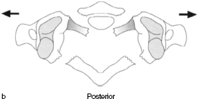
The lateral flexion radiographs are taken in an AP projection. The lateral borders of the dens and lateral masses are the bony landmarks. Atlantoaxial instability manifest itself in the lack of physiologic forced rotation of the dens in the direction of inflammation and in the failure of the atlas to shift in the same direction (Drerup 1985). Increasing lateral flexion will also cause the other cervical vertebrae to rotate; the degree of rotation decreases from cranial to caudal.
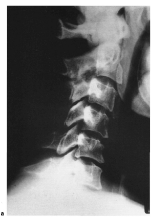
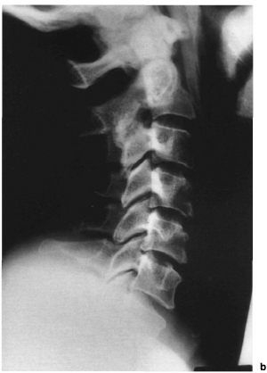
Figs. 8.72a, b Plain radiographs of the cervical spine in flexion and extension. Note the AP translation at C2-C3; (a) flexion, (b) extension.
The motion components of the axis (rotation, tilting, and transverse shift) are tightly integrated. The tilting and transverse shift increase as rotation increases. A disturbance in this motion pattern is apparent in the so-called dissociation phenomenon in which the extent of rotation of the axis and the combined tilting and transverse shift appear dissociated (Dihlmann l987).
Traumatic Changes in the Cervical Spine
Injuries to the cervical spine almost always result from indirect forces acting on the head and skull. The site and nature of damage are determined by the position of the head and cervical spine at the time of the accident. According to Daffner (1986), a force acting on the cervical spine always produces a similar pattern of injury, regardless of the site. A differentiation is made between flexion, extension, compression, shear, rotation, and distraction injuries. The stability of such an injury can be evaluated by examining the spinal ligaments (Fig. 8.73). Holdsworth has defined the so-called posterior ligamentous complex, consisting of the supraspinous ligament, interspinous ligament, and flaval ligaments, and the capsules of the small vertebral joints. If these structures are intact, the fracture can be regarded as stable. Radiologic signs of instability include vertebral displacement an increase in the distance between spinous processes or laminae, gaping facet joints, a widened or elongated spinal canal, or an interruption in the posterior longitudinal line (Daffner 1986). If only one of these criteria is present, then the injury to the cervical spine must be regarded as unstable. However, precise evaluation of the bony architecture of the spinal canal will require CT studies. Soft tissue is best visualized using MRI.
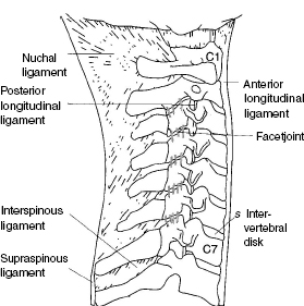
Fig. 8.73 Important ligamentous structures in the cervical spine.
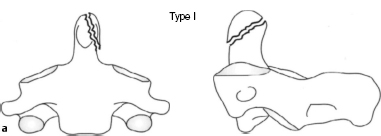
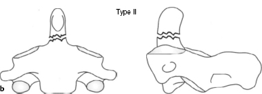
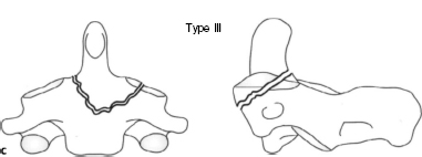
Figs. 8.75a-c Schematic diagram of classification of dens fractures according to Anderson and D’ Alonzo.
Type I: oblique fracture in the upper dens axis area.
Type II: transverse fracture at the base of the dens axis.
Type III: fracture at the base of the dens axis extending into the body of the axis.
• Frequently encountered injuries to the cervical spine
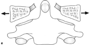
Jefferson fracture. Axial forces acting through the occiput on the atlas and axis can shatter the atlas, causing symmetric fractures of the anterior and posterior arches and tearing the transverse ligament. In a plain radiograph this compression injury is best imaged in the open-mouth odontoid view (Figs. 8.74a, b).
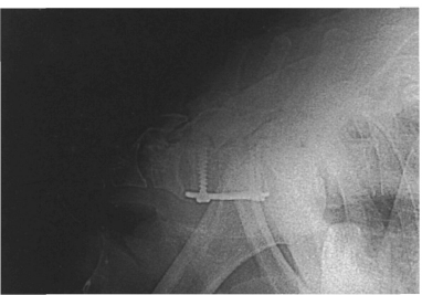
Dens fracture. Hyperflexion of the cervical spine can shift the dens anteriorly. It can also sublux anteriorly between the atlas and axis. In rare cases, hyperextension can result in injury to the dens with posterior subluxation. Dens fracture are also classified according to Anderson and D’ Alonzo (Figs. 8.75a-c). Type I generally involves a diagonal fracture line superior to the base of the dens. Type II describes a fracture through the base of the dens. In type III, the fracture spreads into the body of the axis. These injuries are best diagnosed in a plain radiograph obtained using the conventional open-mouth odontoid view or the Fuchs odontoid process position (Fig. 8.76). Type II fractures according to Anderson and D’Alonzo are accompanied by a higher rate of pseudarthrosis (Fig. 8.77). The differential diagnosis of dens fractures should always exclude an os odontoideum (Fig. 8.78).
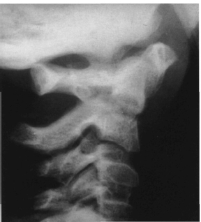
Fig. 8.76 Plain lateral radiograph of the upper cervical spine. Dens fracture in a child.
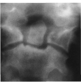
Fig. 8.77 Plain radiograph of the dens (tomography) in the coronal plane. Pseudarthrosis of the dens.
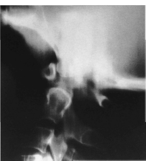
Fig. 8.78 Plain radiograph (lateral tomography) of the upper cervical spine. The image shows typical radiologic changes suggestive of os odontoideum.
Hangman fracture. In 1912 Wood-Jones studied the pathologic mechanism of execution by hanging. He found that simultaneous hyperextension and distraction causes bilateral fractures of the base of the arch of the axis with anterior subluxation and subsequent severing of the spinal cord. This form of fracture is also observed in injuries to the cervical spine involving extension. The lateral projection is best for imaging the fracture in these patients (Figs. 8.79a, b).
Compression fracture. Hyperflexion of the cervical spine results in compression of the anterior aspect of the vertebral body without injury to the posterior ligamentous complex. This is a stable form of fracture and can be demonstrated in a conventional lateral radiograph.
Burst fracture. Axial force acting on the lower cervical vertebrae (C3-C7) can cause a fracture of the end-plate of the vertebra that may extend to the anterior and posterior margin of the body of the vertebra, rupturing the anulus fibrosus and compressing the nucleus pulposus into the neighboring vertebra. The retropulsion of the posterior fragments can result in narrowing of the spinal canal. If the posterior ligamentous complex is also ruptured, then it should be assumed that the fracture is unstable. The comminuted fracture and the posterior margin of the affected vertebral body can be seen on the lateral radiograph (Figs. 8.80a, b).
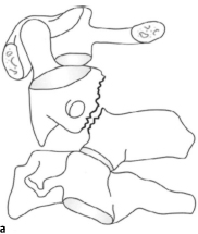
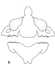
Figs. 8.79a, b Schematic diagram of a hangman fracture. Bilateral fractures of the base of the arch of the axis with anterior subluxation and subsequent severing of the spinal cord.
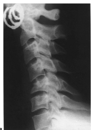
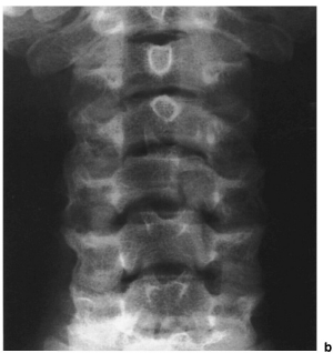
Figs. 8.80a, b Plain radiograph of the cervical spine in two planes showing a burst fracture of C5.
Teardrop fracture. This flexion injury is regarded as the most unstable form of all injuries to the cervical spine. Subluxation or dislocation of the affected vertebra, accompanied by a tear in the posterior capsular ligamentous structures (Fig. 8.81), is the cause of this frequently observed syndrome with immediate quad-riplegia and loss of sensitivity to pain and temperature. The teardrop fragment is created by avulsion of the anterior longitudinal ligament which generally remains attached to a fragment of bone. This fracture can be reliably diagnosed in the lateral radiograph (Figs. 8.82a, b). It is important to distinguish the classic teardrop fracture from the stable avulsion teardrop fracture, in which an anterior bony projection may be seen but the capsular ligaments remain intact and subluxation is not present (Greenspan 1993). These two fractures can be differentiated using CT with a sagittal reconstruction (Fig. 8.198, see p. 388).
Clay-shoveler fracture. Forceful flexion or, in rare cases, direct trauma, can cause an oblique fracture of the spinous process in the sixth or seventh cervical vertebra. This is a stable fracture that can generally be readily diagnosed in the lateral radiograph. If the seventh cervical vertebra is obscured, the swimmer’ s position should be used. In the AP radiograph, the displacement of the fragment will appear as a double-contour spinous process.
Perched facets. A flexion rotation injury causes a rupture of one or both facet joint capsules and the posterior ligamentous complex (Fig. 8.83). This is an unstable injury that is recognizable in the lateral radiography by the subluxation or dislocation of the facet joints in which the articular pillars appear to be shaped like a bat’ s wing.
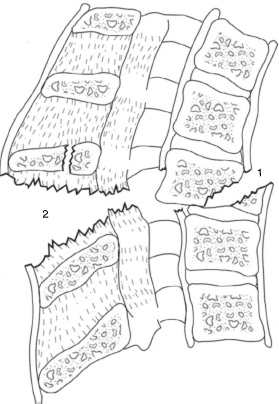
Fig. 8.81 Schematic diagram of a teardrop fracture. In this unstable fracture, a- teardrop-shaped bone fragment is avulsed from the anterior margin of the body of the vertebra (1). The posterior capsular ligaments are also torn (2).
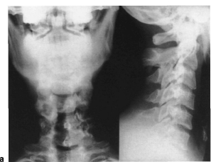
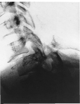
Figs. 8.82a, b Plain radiographs in two planes (a) and lateral spot view (b) of the cervicothoracic region (as shown in Fig. 8.198, p. 388). (a) A fracture is not discernible in the standard radiographs in two planes. However, only six vertebrae are visible in the lateral image, (b) The fracture dislocation is only revealed in the spot view.
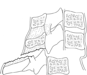
Fig. 8.83 Schematic diagram of a perched facet. The capsule of the facet joints and the posterior ligaments are ruptured. The facet joint has dislocated and the superior joint facet has become wedged in front of the inferior joint facet.
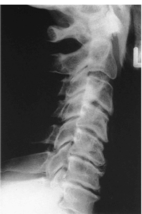
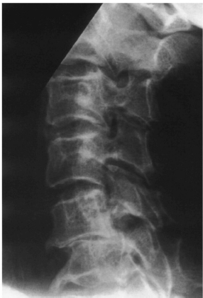
Fig. 8.85 Plain lateral radiograph of the cervical spine. The image shows pseudospondylolisthesis at C5-C6.
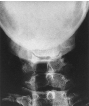
Fig. 8.86 Plain AP radiograph of the cervical spine. Uncover-tebral arthritis in a 25-year-old female patient.
Degenerative Changes in the Cervical Spine
As in the other synovial joints of the human body, degeneration of the cervical spine occurs in the form of arthritic changes (see section Degenerative Changes in the Lumbar Spine). The classic signs of arthritis such as narrowing of the joint space, sub-chondral sclerosis, and formation of osteophytes are observed here as well (Figs. 8.84 and 8.85). Since the thickness of the intervertebral disks decreases with age, uncovertebral arthritis will often develop (Fig. 8.86), which is readily discernible in the AP radiograph. The foramina and the small vertebral joints are easier to evaluate in the oblique views (Fig. 8.87). Extensive spondylarthritis can cause irritation of the nerve roots with pain radiating into the back of the neck, shoulders, and arms. For this reason, oblique views of the cervical spine can provide valuable information in diagnosing a shoulder-arm syndrome. In addition, dynamic views provide important indications of disturbed motion with segmental hypomobility or hypermobility. White etal. (1975) have an instability grading system of the cervical spine. One component of this system includes more than 3.5 mm of AP translation between flexion and extension.
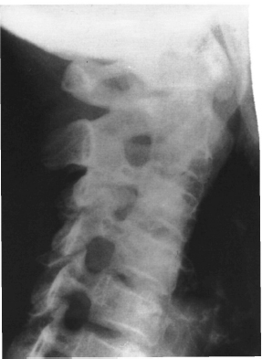
Fig. 8.87 Plain radiograph of the cervical spine, oblique view. The image shows narrowing of the C3-C4 foramen.
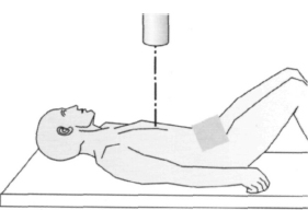
Fig. 8.88 To obtain the AP radiograph of the thoracic spine with the patient supine, the patient’ s hips and knees are slightly flexed. The X-ray beam is aimed at the midline approximately 3 cm superior to the xiphoid process.
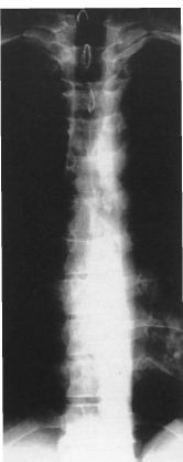
Fig. 8.89 Plain AP radiograph of the thoracic spine. Thirty-four-year-old patient with symptomatictho-racic spine. Radiologie findings are normal for this age (see also Fig. 8.92).
Thoracic Spine
Standard Views
AP view (Figs. 8.88 and 8.89). The thoracic spine can be imaged with the patient standing or lying down. When a radiograph is obtained in the supine position, the patient’ s hips and knees should be flexed slightly to compensate for physiologic kyphosis. This provides exposure of the intervertebral spaces. The central ray is aimed at the midline approximately 3 cm superior to the xiphoid process.
The end-plates of the vertebrae are readily discernible in the supine radiograph, as are the intervertebral spaces. The pedicles appear as oval radiolucen-cies that form the lateral margin of each vertebra. This position also permits evaluation of the costo-transverse joints. The spinous processes appear as drop-shaped projections in the midline.
Lateral view (Figs. 8.90–8.92). A technique similar to tomography is used to image the thoracic spine. The patient breathes shallowly to obscure the surrounding soft tissue and to enhance the section of the spine being imaged. The radiograph can then be obtained with the patient standing with his or her arms raised or lying down. The central ray is aimed at the sixth thoracic vertebra.
The vertebral bodies and intervertebral disk spaces can be readily evaluated in the lateral view. The pedicles and the intervertebral foramina are also imaged. The kyphotic angle in the normal thoracic spine is +20°-+40° according to Cobb (Bernard and Bridwell 1989; Bradford et al. 1974; Moe et al. 1994; Propst-Prockor and Bleck 1983; Roaf 1960). The measurement is taken from the superior end-plate of the fourth vertebral body and the inferior end-plate of the 12th vertebral body. Stagnara et al. (1982) examined 100 test subjects and found an average kyphotic angle of +37° within a range extending from +7°-+63°. The thoracolumbar junction from T10-L2 marks the transition from kyphosis to lordosis and should normally have a neutral orientation. Bernard and Bridwell (1989) observed an average kyphotic value for the superior thoracolumbar spine (T10-T12) of +5.5° within a range from −3°-+20°. The inferior thoracolumbar spine (T12-L2) showed an average lordosis value of -3° within a range extending from -23°-+13°.
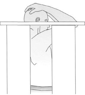
Fig. 8.90 For the lateral view of the thoracic spine, the patient stands with arms raised. The X-ray beam is aimed at the middle thoracic spine at the level of the sixth thoracic vertebra.
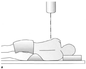
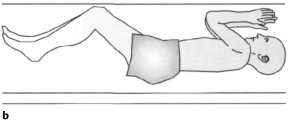
Figs. 8.91 a, b Lateral view of the thoracic spine with the patient lying down. The X-ray beam is aimed at the middle thoracic spine at the level of the sixth thoracic vertebra.
Special Views
Special views such as oblique views or dynamic studies are less common in imaging the thoracic spine. Oblique projections can provide information about bony structures constricting the intervertebral foramina in intracostal neuralgia. Flexion and extension views or lateral bending views can provide important evidence of disturbed motion with segmental hyper-mobility or hypomobility.
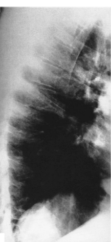
Fig. 8.92 Plain lateral radiograph of the thoracic spine. The image shows the sagittal view of the spine shown in Fig. 8.89. This projection shows normal radiologie morphology for this age.
Traumatic Changes in the Thoracic Spine
Changes to the thoracic spine due to trauma are similar to those in the lumbar spine. The thoracolumbar junction is the region of the spine most frequently affected by spinal injuries. Fora detailed classification of individual fractures, see the section on the lumbar spine.
Degenerative Changes in the Thoracic Spine
As in the cervical and lumbar spine, degenerative changes in the thoracic spine are characterized by narrowing of the joint spaces with subchondral sclerosis and especially with development of osteophy-tes. Spondylosis deformans (Figs. 8.93a, b) is characterized by the development of anterior and lateral osteophytes. The intervertebral disks may be intact or may exhibit symptoms of degenerative disk disease. In the lateral view, spondylosis must be distinguished from ankylosing spondylitis (Bechterew disease) with fine syndesmophytes and from Forestier disease, diffuse idiopathic skeletal hyperostosis (DISH). An anterior prolapsed intervertebral disk can appear as a small triangular bony projection, the limbus vertebrae, which should not be confused with a fracture (Greenspan 1993).
Lumbar Spine
Standard Views
AP view (Figs. 8.94 and 8.95). The lumbar spine can be imaged with the patient standing or lying down. When a radiograph is obtained in the supine position, the patient’ s hips and knees should be flexed slightly to compensate for the physiologic lordosis. This provides exposure of the intervertebral spaces. The central ray is aimed at the midline at the level of the iliac crests. The image with the patient standing is also suitable for documenting functional changes. You can evaluate whether the axis of the pelvis and sacrum is vertical. Evaluating the sacral axis is particularly important since the iliac crests will often be asymmetric.
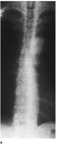
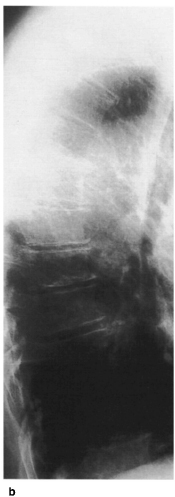
Figs. 8.93a, b Plain radiographs of the thoracic spine in two planes. Degenerative changes of the thoracic spine.
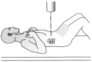
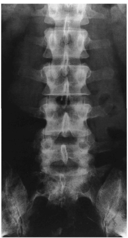
Fig. 8.95 Plain AP radiograph of the lumbar spine. The image shows normal findings in the lumbar and lumbosacral spine (see also Fig. 8.97).
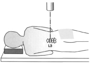
Fig. 8.96 Lateral view of the lumbar spine with the patient lying down. The X-ray beam is aimed at the middle lumbar spine at the level of the third lumbar vertebra.
The end-plates of the vertebrae with the adjacent intervertebral disk spaces, pedicles, the drop-shaped projection of the spinous processes, and the transverse processes are readily discernible. The inferior end-plates of the lumbar spine have the characteristic form of Cupid’ s bow.
Special views may be used to evaluate the lum-bosacral junction. Accurate identification of the number of lumbar vertebrae is necessary. This may require obtaining a full-length spine radiograph; the vertebrae are counted starting at Cl. It is possible for S1 to be included in the lumbar spine, i.e., six lumbar vertebrae, and conversely for L5 to be included in the sacrum, i.e., four lumbar vertebrae (Heine 1980) (Figs. 8.55a-c, p. 316).
Lateral view (Figs. 8.% and 8.97). The lateral radiograph of the lumbar spine may be obtained with the patient standing or lying down. The central ray is aimed at the middle of the third lumbar vertebra.
The lateral view allows evaluation of the vertebral bodies as well as of the height of the intervertebral spaces, pedicles, intervertebral foramina, and spinous processes. The lordosis of the lumbar spine measured from L1-L5 ranges from -14°—69° with a mean value of-44°according to Cobb. Other authors (DeSmet 1985; Propst-Proctor, Bleck 1983) have determined similar ranges for lumbar lordosis extending from -20° – -60°.
Special Views and Dynamic Studies
Oblique views. The patient is placed in a 45° lateral oblique position (Fig. 8.98). The PA projection images the side to which the patient is turned. This imaging technique allows evaluation of the facet joints with the superior and inferior articular processes (Fig. 8.99), the intervertebral foramen, the bases of the vertebral arch, and the pars interarticularis. The oblique view shows the characteristic arrangement of a “Scottie dog” (Fig. 8.114) and is an important projection for diagnosing spondylolysis and degenerative changes of the lesser vertebral joints.
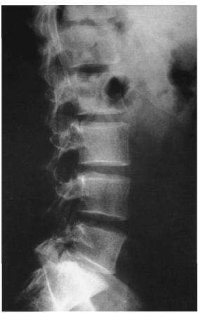
Fig. 8.97 Plain radiograph, lateral projection, of the lumbar spine. The image shows the sagittal view of the spine shown in Fig. 8.95 with normal findings.
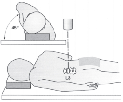
Fig. 8.98 The oblique view of the lumbar spine for evaluating the facet joints and the intervertebral foramina can be obtained with the patient placed in a 45° lateral oblique position. The X-ray beam is aimed at the middle lumbar spine at the level of the third lumbar vertebra and images the ipsilat-eral facetjoints.
Dynamic views. These include the lateral flexion-extension view and the AP bendingviews. The latter are especially important for evaluating scoliosis and segmental hypermobility in the coronal plane. They are obtained with the patient positioned supine and at the maximum lateral bend (see section Scoliosis, Radiographic Studies). The lateral dynamic views are used to detect disturbed motion with segmental hypermobility or hypomobility in patients with back pain (see section Degenerative Changes in the Lumbar Spine, Figs. 8.100a, b and 8.101 a, b).
Conventional tomography. Before the era of CT, this was regarded as a valuable means of imaging. In current use, it has fallen from favor due to its relatively high radiation doses and limited utility. CT has replaced plain tomography except in the evaluation of spondylolysis (Brant-Zawadzki et al. 1981).
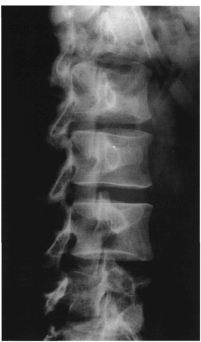
Fig. 8.99 Plain radiograph of the lumbar spine in an oblique position. This is a normal study. The individual facetjoints are readily discernible in this view.
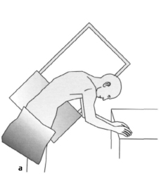
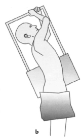
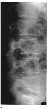
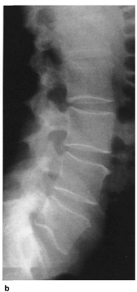
Figs. 8.101 a, b Plain radiograph of the lumbar spine showing lateral dynamic views. Aside from slight anterior osteophytes at the superior end-plate of the fourth vertebra, the image shows a lumbar spine with normal mobility. There is no evidence of hypermobility of individual segments of the spine, (a) Flexion, (b) extension.
Traumatic Changes in the Lumbar and Thoracic Spine
Since the middle of the century there have been efforts to classify spinal injuries (Böhler 1951). Nicoll was the first to separate fractures into the two large groups of stable and unstable fractures. Holdsworth contributed decisively to the understanding of spinal injuries by developing his two-column concept (Fig. 8.102). He distinguished between the anterior column and the so-called posterior ligamentous complex which he viewed as crucial to stability. Denis minimized the importance of the posterior column and proposed the three-column concept of the spinal column (Fig. 8.103). Here, the anterior column included the anterior longitudinal ligament, the anterior margin of the vertebral body with the superior and inferior end-plates, and the intervertebral disk with the anterior aspects of the anulus fibrosus and the nucleus pulposus. The posterior column is formed by the bases of the vertebral arch, the facet joints with their capsular attachment, and the spinal ligaments (the flaval ligaments, the interspinous ligament, and the supraspinous ligament), corresponding to Holds-worth’s posterior ligamentous complex. The posterior aspects of the anulus fibrosus, the posterior margin of the vertebral body, and the posterior longitudinal ligament represent the medial column that is crucial for stability of the injury. If the middle column is compromised there is a risk of damage to the spinal cord due to fracture fragments projecting into the spinal canal.
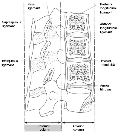
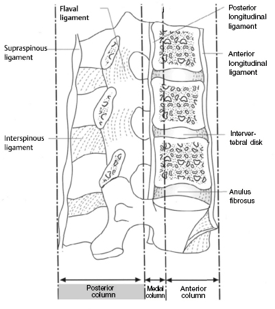
Fig. 8.103 Schematic diagram of Denis’ three-column concept as seen in a lateral projection.
The Denis classification differentiates between compression, burst, seat-belt, and dislocation injuries. Compression fractures represent a collapse of the superior or inferior end-plate without involvement of the posterior margin of the vertebral body and are classified as types A–D (Figs. 8.104a–d and 8.105).
Burst fractures are compression factors involving the posterior margin of the vertebra and are divided into five types (Figs. 8.l06a–e, 8.107a, b and 8.108). Seat-belt injuries represent a group of flexion-distraction injuries and are classified according to the bony structures involved (Figs. 8.109a–d). The final category, dislocation injuries, consists of all injuries involving all three columns and includes flexion-rotation, shear, and flexion-distraction injuries (Figs. 8.110a–d, 8.111, and 8.112). According to Denis, the stability of an injury to the spinal column is determined by the number of affected columns. Single-column injuries are generally stable, three-column injuries are always unstable, and two-column injuries may be stable or unstable depending on the severity. The transition from stable to unstable can be gradual. Denis introduced the concepts of mechanical and neurologic instability. According to this system, severe compression fractures and flexion-distraction injuries should be regarded as mechanically unstable because they involves a risk of subsequent deformity. Burst fractures without primary loss of neurologic function belong to the class of neurologically unstable fractures. They can lead to progressive deformation with resulting secondary neurologic deficits. Burst fractures with primary neurologic symptoms and fracture dislocations are among the fractures that are both mechanically and neurologically unstable.
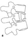
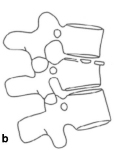
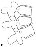
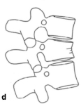
Figs. 8.104a–d Schematic classification of compression fractures according to Denis.
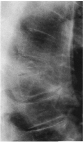
Fig. 8.105 Plain lateral radiograph of the thoracic spine showing an old compression fracture of the ninth thoracic vertebra with osteoporosis.
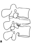
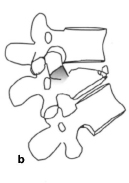
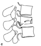
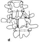
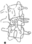
Figs. 8.106a–e Schematic diagram of the burst fractures according to Denis,
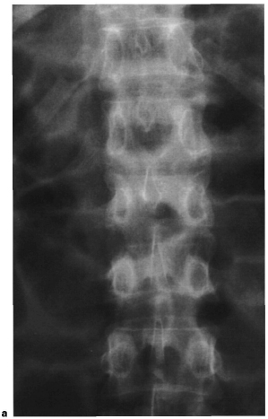
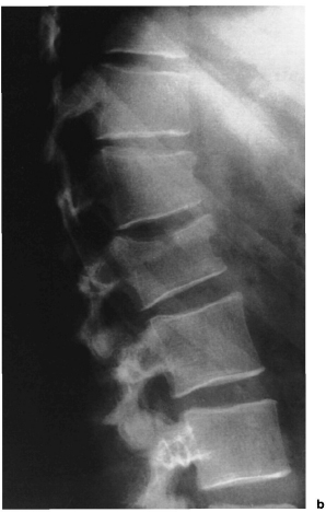
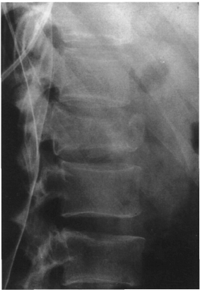
Fig. 8.108 Plain lateral radiograph of the lumbar showing a severe burst fracture of the first lumbar vertebra.
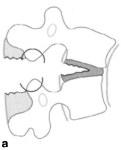
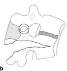
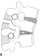
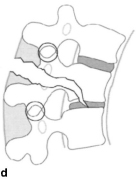
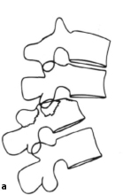
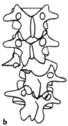
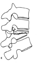
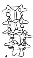
Figs. 8.110a–d Schematic diagram of dislocation fractures according to Denis.
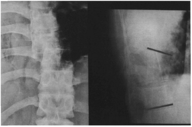
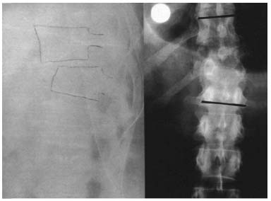
Fig. 8.112 Plain radiograph of the thoracolumbar spine in two planes showing a fracture dislocation at T9–T10 (from Castro W. M., Schiigen, M., reuzsch merzen, Springer Verlag 1995).
McAfee et al. (1983), Magerl et al. (1994), and Harms (1987) have developed further classifications of spinal column injuries based on Denis’ three-column principle according to pathogenesis. McAfee described three different forces that can act on the medial column in a spinal injury. These include axial compression, axial distraction, and translation in the transverse plane. Where there is simultaneous translation and compression or distraction, the transverse force is the decisive factor in evaluating the instability of the injury.
Based on the form of injury to the medial column, injuries are classified as follows: wedge compression fractures (exclusively involving compression of the anterior column); stable burst fractures (with the posterior column intact) and unstable burst fractures (with compression, rotation, or translation of the posterior column); chance fractures (flexion injury with its axis anterior to the anterior longitudinal ligament that results in a distraction injury to all three columns); flexion-distraction injuries (flexion injury with its axis posterior to the anterior longitudinal ligament as results in a compression injury to the anterior column and a distraction injury of the middle and posterior columns); translational injury in the form of a shear dislocation injury as described by Denis.
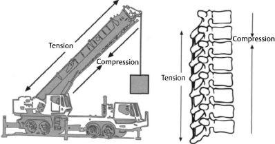
The most current classification system was developed by Magerl et al. This system is again based on a two-column model, this time the one described by Whitesides (Fig. 8.113). According to this system, the anterior column formed by the vertebral bodies is the section of the spinal column that is subjected to compressive loads, whereas the posterior column consisting of the posterior bony structures and the ligaments is primarily subjected to tensile loads. This classification system is based on the respective pathomorpho-logic characteristic of the injury. It uses a rigid three-tier scheme, each with three sublevels, corresponding to the AO/ASIF classification system. Fractures are first divided into three large groups according to the mechanism of injury.
Type A injuries involve compression of the vertebral body, type В injuries involve distraction of the anterior and/or posterior column, and type C injuries involve a rotation injury to the anterior and posterior columns.
Each group is divided into three subgroups according to the respective severity of the injury. These subgroups are themselves divided into further subgroups that specify the injury in greater detail.
Type A injuries. These injuries are caused by axial compression of the vertebral body with or without flexion. A1 injuries include the less severe forms in which there is no risk to the spinal canal. A2 injuries involve fragmentation of the vertebral body in the sagittal or coronal plane due to axial compression (“split fractures”). The posterior margin of the vertebral body remains intact so that loss of nerve function is rare. A3 injuries include the forms of the classic burst fracture. Depending on the severity, the vertebral body will burst to a certain extent with a fracture of the posterior margin of the vertebral body and loss of neural function corresponding to the degree to which the spinal canal is narrowed. The vertebral arch or spinous process may be vertically fractured, but this will have a negligible effect on stability. A3 injuries are always regarded as unstable, especially flexion-compression injuries. The overall incidence of neurologic complications is cited at 14%.
Type B injuries. These injuries are caused by distraction in a flexion or extension injury. Bl and B2 injuries are flexion injuries involving either primarily ligamentous structures (Bl) or bony structures (B2). Bl injuries involve a tear in the posterior ligamentous structure; often the classic joints will be subluxed, dislocated, or fractured. This may be associated with a type A injury to the vertebral body. B2 injuries are characterized by transverse fractures of the laminae or pedicles. The greater the transverse tear, the greater the instability of the injury. Neural involvement is generally higher than in type A injuries. These injuries are generally unstable in flexion; more extensive forms are also unstable in the transverse plane (in the direction of shear) and axially if accompanied by a type A injury. B3 injuries are hyperextension injuries with distraction of the anterior column that can extend posteriorly. This form of injury is relatively rare and involves a high rate of neurologic complications. The overall incidence of neurologic complications in type B injuries is cited at 32%.
Type C injuries. This form of injury describes a rotational injury of the spinal column that involves the anterior and posterior columns and must be regarded as the most unstable form of spinal injury. Cl injuries are type A injuries with a rotational component; accordingly, C2 injuries are type B injuries with a rotational component. C3 injuries are rotational shear injuries and are regarded as the most unstable of all spinal injuries. The overall incidence of neurologic complications in type C injuries is cited at 55%.
Spondylolysis and Spondylolisthesis
Spondylolysis is characterized by a congenital or acquired defect in the pars interarticularis. In 90% of all cases, the L4 or L5 vertebrae are affected. The defect is clearly discernible in the oblique radiograph as a “collar” on the “Scottie dog” figure (Figs. 8.114, 8.115, and 8.116). As a result of the defect, the superior vertebra can slide over the inferior one, resulting in spondylolisthesis.
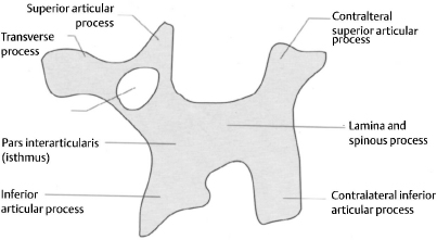
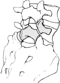
Fig. 8.115 Schematic diagram of an oblique radiograph of the lumbar spine showing the “Scottie dog” figure. Its “collar,” the defect in the pars interarticularis, is a sign of spondylolysis.
Wiltse (1976) classifies spondylolisthesis into five different types:
– Dysplastic form with a congenital defect of the pars interarticularis.
– Isthmic form with a lesion in the pars interarticularis due to a fatigue fracture or from elongation without lysis.
– Degenerative form as a result of chronic segmental instability.
– Traumatic form with a fracture of the pars interarticularis.
– Pathologic form with local or generalized bone disease.
Genuine spondylolisthesis, with lysis of the pars interarticularis, should be distinguished from pseudospondylolisthesis, which is characterized by an intact pars interarticularis and results from subluxation of the small vertebral joints due to degenerative processes. In the conventional lateral view of the lumbar spine, spondylolisthesis can be diagnosed from the slippage of the superior vertebra over the inferior one. A step will be visible in the row of spinous processes. In genuine spondylolisthesis this step will be superior to the level of slippage; in pseudospondylolisthesis it will be inferior to it in the form of a spinous process sign (Figs. 8.117a, b). The severity of spondylolisthesis is diagnosed on a scale of 1–4 using the Meyerding system according to the extent of anterior slippage (Figs. 8.118a–d). This is done using the lateral radiograph (Figs. 8.119a, b and 8.120a, b).
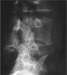
Fig. 8.116 Plain radiograph of the thoracolumbar spine in an oblique projection. The arrows indicate the “Scottie dog’s collar,” a sign of spondylolysis.
In spondyloptosis, the most severe form, the superior vertebra will be seen to completely slip off the inferior one (Fig. 8.121). Severe spondylolisthesis of L5 or S1, with an anteroinferior shift of L5 in relation to S1, will appear on the AP radiograph as a Figure resembling an upside-down Napoleon’s hat (Fig. 8.122). Generally, spondyloptosis will occur as the result of a tilting and rolling motion. However, cases have been described in which the fifth lumbar vertebra slips anteriorly on to S1 and drops down without tilting (Imhäuser 1988). Even the less severe forms of spondylolisthesis will produce lumbosacral kyphosis in addition to the translational deformity. This kyphosis can significantly influence the overall stability of the spinal column. The kyphotic angle is calculated from the tangent of the posterior margin of the sacrum and the inferior end-plate of slipping vertebra (Fig. 8.123).
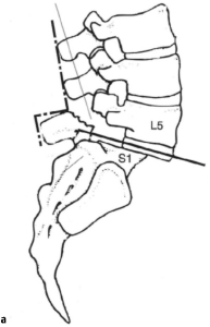
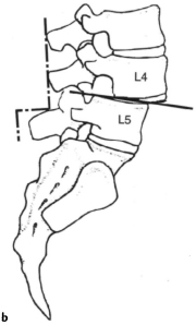
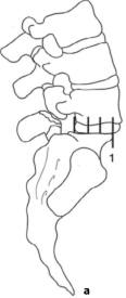
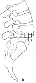
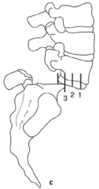
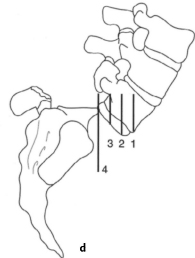
Figs. 8.118a–d Schematic diagram of Meyerding’s system for classifying the severity of lumbar spondylolisthesis: (a) grade I, (b) grade II, (c) grade III, (d) grade IV.
Degenerative Changes in the Lumbar Spine
Degenerative changes in the lumbar spine affect the intervertebral disks, joints, vertebral bodies, and spinal ligaments. These changes appear as osteochondrosis, spondylosis, and spondylarthritis and are frequent observed together. Degenerative disk disease is characterized by a reduction in the height of the intervertebral space with an increase in the radiodensity of the end-plate of the vertebrae due to subchondral sclerosis (Fig. 8.124). According to Krämer, degeneration of the intervertebral disk and the resulting loss of height cause segmental loosening with secondary overloading of the vertebral joints. Aside from the reduction in height, disk degeneration is occasionally discernible in the plain radiograph from the “vacuum phenomena” resulting from gas inclusions within the disks (Fig. 8.125). Degeneration of the intervertebral disk with advancing age can be readily evaluated with discography and MRI. The role of discography in degenerative disk disease is controversial.
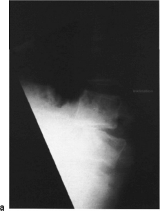
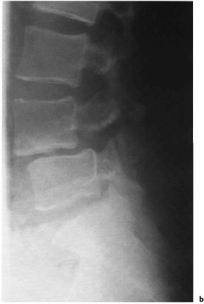
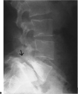

Figs. 8.120a, b Lateral (a) and oblique (b) plain radiographs of the lumbar spine showing dysplastic spondylolisthesis of the lumbar spine (Meyerding grade II).
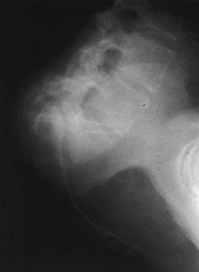
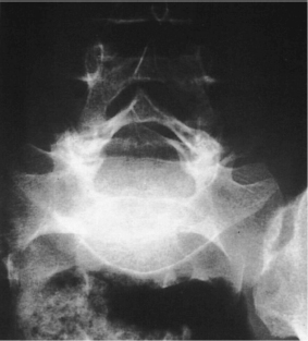
Fig. 8.122 Plain AP radiograph of the lumbosacral spine showing spondyloptosis with the Figure of Napoleon’s hat upside down.
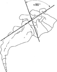
Fig. 8.123 Schematic diagram for calculating the angle of lumbosacral kyphosis.
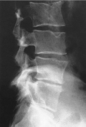
Fig. 8.124 Plain lateral radiograph of the lumbar spine. In addition to Schmorl nodules on the second and third lumbar vertebrae, the image shows narrowing of the intervertebral space in the two lower segments accompanied by subchondral sclerosis. A posterior spondylophyte can be seen on the inferior end-plate of the fourth lumbar vertebra.
Spondylosis (Figs. 8.126a, b) refers to the development of osteophytes on the end-plates of the vertebrae, frequently associated with degenerative disk disease (known as marginal spondylophytes). Sub-marginal spondylophytes occur more frequently in intervertebral spaces of normal height and result in a reaction to increase tensile loading of the anterior longitudinal ligaments with segmental hypermobility. MacNab studied this phenomena in 1971 and referred to this form of spondylophytes as “traction spur” (Fig. 8.127).
Spondylarthritis refers to degeneration of the facet joints, also known as degenerative joint disease of the spine. This disorder is best detected in oblique radiographs that will reveal the classic signs of arthritis of the small vertebral joints, including narrowing of the joint space, subchondral sclerosis, and formation of osteophytes (spondylophytes; Figs. 8.128 and 8.129). When the sacrum is included in the AP radiograph, the sacroiliac joints are readily visible. If arthritic changes are present in this region, the possibility should be considered of ankylosing spondylitis in its early stages that will often manifest itself as sacroiliitis.
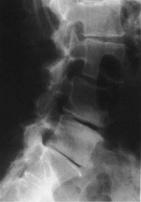
Fig. 8.125 Plain lateral radiograph of the lumbar spine. In addition to spondylolisthesis at L3–L4, the image demonstrates a “vacuum phenomenon,” in the two inferior segments associated with degeneration of the intervertebral disk (see also Fig. 8.130).
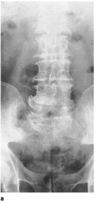
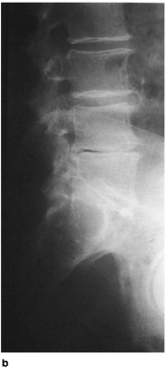
Figs. 8.126a, b Plain radiograph of the lumbar spine in two planes. The image shows degenerative changes, particularly in the two inferior lumbar spine segments where narrowing of the intervertebral disk and spondylosis is present. A vacuum phenomenon can be seen at L4–L5 (from Castro W. M., Schilgen, M, Kreuz-schmerzen. Springer Verlag 1995).
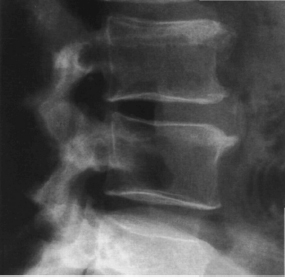
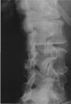
Fig. 8.128 Plain radiograph of the lumbar spine in an oblique projection. The facet joint L3–L4 shows a vacuum phenomenon in addition to degenerative changes. The other facet joints, particularly L4–L5 and L5–S1 (only partially visible) show degenerative changes but without a vacuum phenomenon.
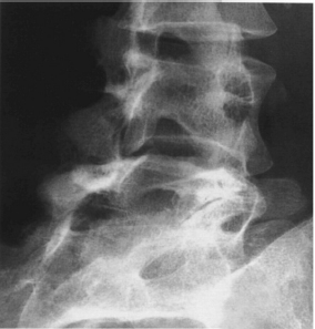
Fig. 8.129 Plain radiograph of the lumbar spine in an oblique projection showing arthritis of the lumbosacral facet joints.
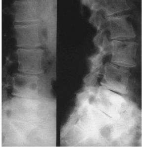
Fig. 8.130 Plain radiograph of the lumbar spine showing lateral dynamic views. The images demonstrate degenerative spondylolisthesis at L3–L4 (see also Fig. 8.125).
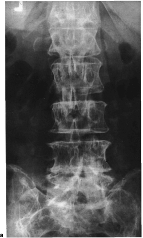
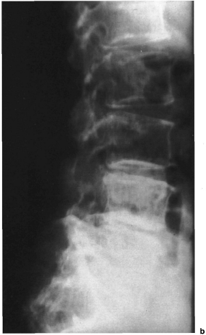
Degenerative segmental instability, or degenerative spondylolisthesis from sub luxation of the small vertebral joints, spinal stenosis resulting from development of osteophytes on the articular processes, and hypertrophy of the flaval ligament are regarded as results of degenerative spinal disease. Degenerative segmental instability can be diagnosed in plain radiographs using lateral flexion and extension views. Normal values and pathologic values cited by various studies overlap. According to Boden and Wiesel (1990), dynamic AP translation (after allowing for the translation inherent in the extension and flexion view) that exceeds 3 mm, or 8% of the width of the vertebral body, is indicative of segmental hypermobihty (Boden and Wiesel 1990) (Fig. 8.130). The normal values of segmental sagittal translation and segmental sagittal angular rotation are shown in Tables 8.29 and 8.30.
Plain radiographs are inferior to myelography, CT, and MRI for detecting spinal stenosis. The “clothespin sign” in the AP image and short pedicles in the lateral radiograph may be signs of central spinal stenosis (Figs. 8.131 a, b).
“Kissing spine,” where the spinous processes are seen to impinge on the lateral radiograph, can be either an incidental finding or a painful idiopathic disorder (Figs. 8.132a, b).
| Dynamic sagittal translation in mm | |
| L1–L2 | 1.4mm |
| L2–L3 | 1.3 mm |
| L3–L4 | 1.2mm |
| L4–L5 | 1.2mm |
| L1–S1 | 1.0mm |
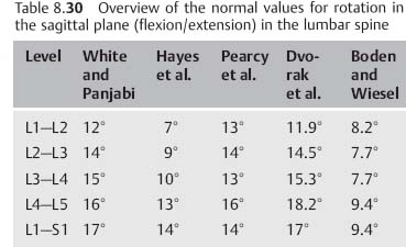
Inflammatory Changes in the Spine
Vertebral osteomyelitis is almost always the result of hematogenous dissemination of pyogenic pathogens that often begin in the subchondral region of the vertebral body. If the focus of the infection breaks through the end-plate of the vertebra and spreads to the intervertebral disk, diskitis will result. This will appear on the plain radiograph as a narrowing of the intervertebral space with destruction of the adjacent end-plates and a soft-tissue abscess visible in the form of a paraspinal mass. In the AP radiograph, a soft-tissue abscess will generally appear as a paravertebral widened area in the shape of an hourglass. Primary hematogenous diskitis only occurs in children because at this age the intervertebral disk still has its own blood supply. In adults, disk infection occurs as a result of direct inoculation of pathogens during surgery or discography.
In an appropriate clinical setting, isolated narrowing of an intervertebral disk seen on a standard radiograph (Figs. 8.133a, b and 8.134a–c) should be regarded as vertebral osteomyelitis and diskitis until proven otherwise. Appropriate diagnostic studies include nuclear medicine scans and MRI. Disk space aspiration and vertebral body biopsy will be required to identify the organism.
Spinal tuberculosis (Pott disease) is most frequently observed in the inferior thoracic and superior lumbar spine. The radiologic features of this disorder resemble a pyogenic infection and frequently include paraspinal masses; occasionally a psoas abscess can burst forth from beneath the inguinal ligament. MRI is the imaging study of choice following plain films.
Rheumatoid arthritis is the primary nonbacterial inflammatory disorder of the cervical spine. Erosion of the dens and destruction of the ligamentous structure posterior to the dens can result in severe atlantoaxial instability, including sub luxation. Subluxation can be documented by an increase in the anterior atlantodental distance to more than 3 mm when inclined. For further diagnostic information, an axial imaging process such as CT or MRI is helpful for evaluating the spinal canal and the inflammatory soft-tissue changes (Krämer 1994).
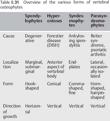
With progression of the disease, subsidence of the lateral masses and the vertebral body of C2 can cause the skull to sink relative to the dens so that it becomes invaginated in the foramen ovale. This is known as pseudobasilar impression (Krämer).
Rheumatoid arthritis can also affect the intervertebral disks, vertebral joints, spinous processes, and the ligamentous structures (Figs. 8.135a, b). The resulting segmental loosening can appear in the radiograph as a characteristic step sign (Kramer).
Facet ankylosis is also observed with rheumatoid disorders. Ankylosis occurs in association with primary chronic polyarthritis, although it occurs more frequently with ankylosing spondylitis. Fine syndes-mophytes and ankylosis of the facet joints are typical signs of this disorder (Greenspan 1993).
Forestier disease or diffuse idiopathic skeletal hyperostosis (DI SH) is typified by continuous ossification of the anterior aspects of the vertebral bodies, extending past the intervertebral disk spaces that are generally well preserved (Figs. 8.136a, b). Differential diagnosis should also include psoriatic arthritis, which can be associated with solitary paraspinal ossifications (parasyndesmophytes). In contrast to the syndesmophytes in ankylosing spondylitis, these rarely bridge the intervertebral space and are almost always limited to one vertebra or occur without bony connections in paravertebral connective tissue (Table 8.31).
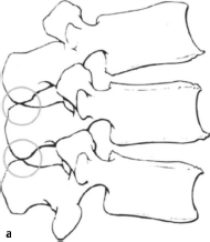
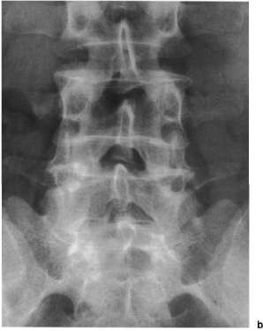
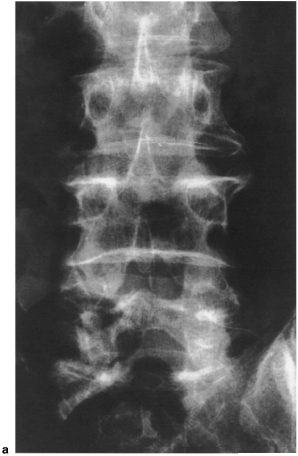
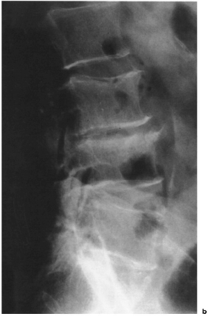
Figs. 8.133a, b Plain radiograph of the lower lumbar spine in two planes. The image shows vertebral osteomyelitis at the L3–L4 level in a 55-year-old patient.
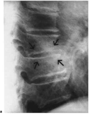
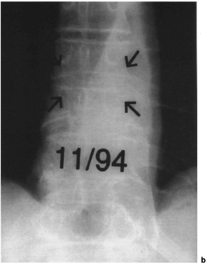
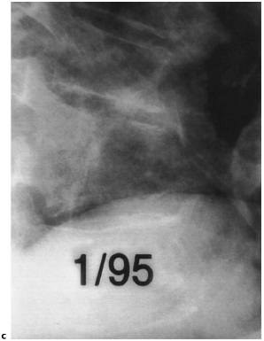
Tumors of the Spine
When radiologic examination reveals pathologic findings in the spine, tumor should always be excluded. Malignant changes are generally observed in the vertebral body; benign tumors will more frequently involve the posterior vertebral structures (Greenspan 1993). On the whole, however, it is extremely difficult to distinguish between benign and malignant tumors in the spine (Wolf and Gnann 1984). Benign lesions tend to be regular and sharply demarcated by a sclerotic halo. In contrast, malignant tumors tend to appear as ill-defined lesions without a sclerotic halo. The most common malignant processes in the spinal column is metastases (Gradinger et al. 1989, Wuisman et al. 1989). Metastases are often localized in the inferior segments of the spinal column, particularly between the second and fourth lumbar vertebrae (Thumler et al. 1987). Table8.32 provides an overview of the various types of malignant spinal tumors.
Primary malignant bone tumors include Ewing sarcomas, chondrosarcomas, and osteosarcomas, although these rarely affect the spinal column. Osteosarcoma of the spinal column generally occurs after exposure to radiation or in association with underlying Paget disease. Chondrosarcomas generally grow more slowly than osteosarcomas and Ewing sarcomas (Salzer-Kuntschik 1984) (Figs. 8.137a,b).
• Metastases • Osteosarcoma • Multiple myeloma • Ewing sarcoma • Chordoma • Chondrosarcoma |
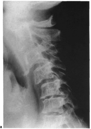
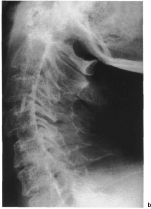
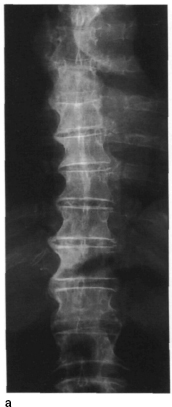
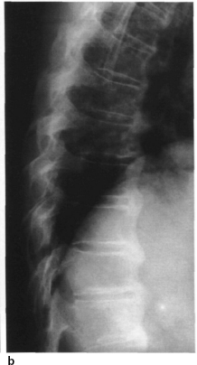
Figs. 8.136a, b Plain radiographs of the thoracic spine in two planes. The images show typical changes associated with Forestier disease(DISH).
• Breast • Thyroid • Lung • Kidney • Prostate • Melanoma |
A chordoma is a malignant tumor derived from persistent portions of the notochord; it occurs exclusively in the midline of the skeleton (Salzer-Kuntschik 1984) and is generally localized in the sacrum.
The primary malignant bone tumor most frequently encountered is multiple myeloma (Greenspan 1993). On plain radiographs it will appear as diffuse osteoporosis with subsidence of the vertebral body and multiple-level compression fractures with osteolysis at multiple sites, some accompanied by reactive sclerosis. The bases of the vertebral arch are rarely affected in the early stages of the disorder due to their relatively low content of red bone marrow.
Metastatic disease is the most frequent form of spinal tumor. It will often cause destruction of the bases of the vertebral arch (Jacobson sign; Fig. 8.138). In the AP radiograph, the destruction of the pedicle is readily discernible as a lack of an oval window or a lytic reaction. The profuse vascularization of bone permits hematogenous dissemination of carcinomas such as breast, prostate, and bronchial cancers (Table 8.33). Due to the paired or segmental vascular supply, most metastases will begin in the vertebral body (Gradinger et al. 1989). In a plain radiograph, bone metastases will appear as circumscribed areas of osteolysis with or without a sclerotic halo or as radiodense foci. In other cases, subsidence of a vertebra is the first sign of metastatic disease. Among the primarily osteolytic metastases are metastases of kidney and thyroid cancers. Breast carcinoma can occur in a mixed form (Figs. 8.139a, b); metastases of prostate carcinomas are generally osteoblastic (Figs. 8.140a, b).
Benign bone tumors that involve the spinal column relatively frequently (Table 8.34) include aneu-rysmal bone cysts, frequently visible as multicystic, eccentrically expanding lesions with a narrow clamshell-shaped periosteal reaction. Since these lesions frequently recur after resection, they are regarded as aggressive benign tumors. A hemangioma is a tumor originating in the blood vessels with characteristic coarse vertical stripes on the vertebral body resembling corduroy or a honeycomb pattern (Figs. 8.141 a–c). Another benign lesion that can affect the spinal column is the osteoid osteoma, a bony tissue change with a typical central nidus. A relatively frequent location of this lesion is the posterior bony column of the spinal column. The nidus, which consists of osteoid or mineralized immature bone, can either be radiolucent or sclerotic. If the nidus is calcified, it will be almost impossible to distinguish it from an osteoblastoma, a related lesion (Wolf and Gnann 1984).
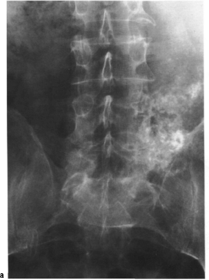
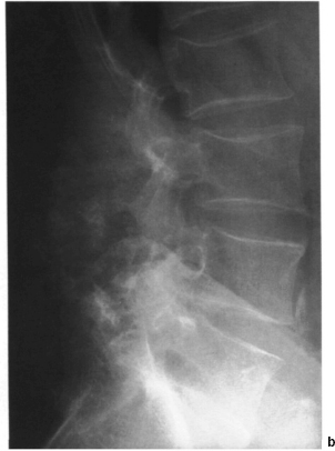
Figs. 8.137a, b Plain radiographs of the thoracic spine in two planes. The images show a large tumor at the lumbosacral junction. Diagnosis: chondrosarcoma.
• Osteoid osteoma • Osteoblastoma • Eosinophilic granuloma • Isolated bone cyst • Hemangioma • Aneurysmal bone cyst • Giant cell tumor |
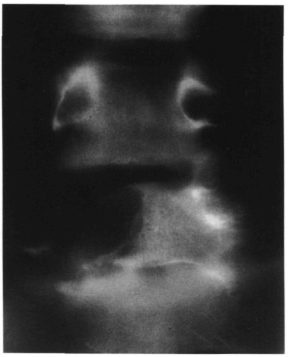
Fig. 8.138 This Ap tomogram shows massive lytic reaction (Jacobson sign) due to metastasis from melanoma.
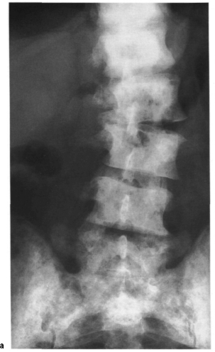
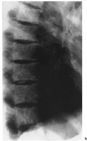
Figs. 8.139a, b Plain radiographs of the lumbar spine in the coronal plane (a) and thoracic spine in the sagittal plane (b). The image shows diffuse skeletal metastases of a breast carcinoma of mixed osteolytic and osteoblastic type. Fig. 9.25 (p. 432) demonstrates the pelvis and hips of the same patient.
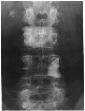
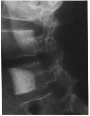
The osteoblastoma is a benign bone tumor involving the spinal column in 30-40% of all cases (Huvos 1979, Marsh et al. 1975). Generally the posterior vertebral elements will be affected, with possible spreading to the vertebral body; the tumor is rarely limited to the vertebral body (Nemoto et al. 1990). In the plane radiograph, it will generally appear as a lobular, well-defined contour (Figs. 8.142a, b).
Eosinophilic granulomas belong to the group of reticuloendothelial proliferations. When they involve the spinal column, almost complete subsidence of the vertebral body can be observed with the intervertebral spaces unaffected. This appears as vertebra plana on the lateral radiograph (Figs. 8.143a, b).
Giant cell tumors involve the spinal column relatively frequently. Wuisman et al. (1989) cite the incidence of involvement of the spinal column as approximately 7%. Because of its high incidence of recurrence and aggressive local growth, the giant cell tumor is regarded as aggressive but benign. However, metastases of giant cell tumors have also been described.
Isolated bone cysts are among the lesions that resemble tumors. They are benign and only rarely involve the spinal column (Dahmen and Bernbeck 1987).
Spinal Deformity
Scoliosis
Spinal deformity is understood to mean deviations from normal in the coronal and sagittal planes. Scoliosis is defined as a structural lateral curve in the spinal column with a rotational component and resulting deformity in the sagittal plane. Curves of less than 10° do not represent scoliosis. Depending on location, a differentiation is made between thoracic, thoracolumbar, lumbar, and double curve scoliosis (Fig. 8.144a–d). Ponseti and Friedman (1950) first defined a systematic classification of scoliotic curves that was slightly modified by Moe et al. (1994).
According to this scheme, lumbar scoliosis is defined as having its apex at L2 with predominantly left convex curves. If the apex of the curve is at T12 or L1, the disorder is a thoracolumbar scoliosis that is predominantly right convex. Thoracic scoliosis is predominantly right convex with the apex of its curve between T7 and T11.
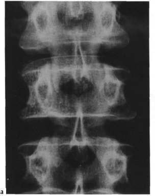
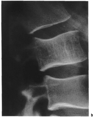
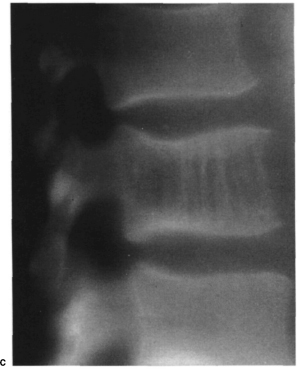
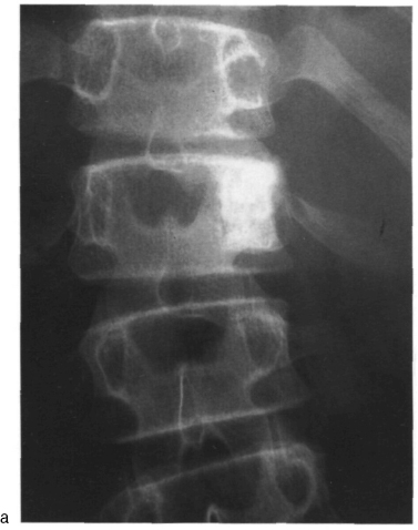
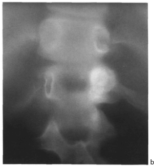
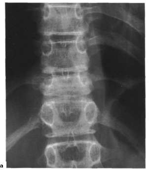
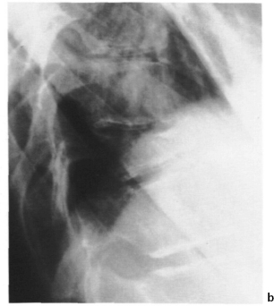
Figs. 8.143a, b Plain radiographs of the thoracolumbar spine in two planes. The images demonstrate subsidence of vertebral body T11, diagnosed as eosinophilic granuloma.
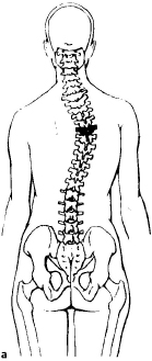
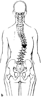
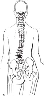
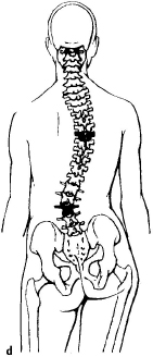
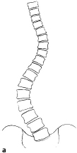
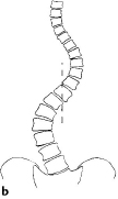
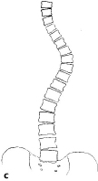
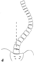
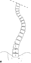
Figs. 8.145a–e Schematic diagram of five types of scoliotic curves (l–V) according to King, (a) type I, (b) type II, (c) type III, (d) type IV, (e) type V.
Idiopathic right convex thoracic scoliosis, which comprises by far the largest share of idiopathic scoliotic disorders, is further subdivided according to King’s classification (King et al. 1983) (Table 8.35, Figs. 8.145a–e and 8.146–8.157).
A new classification by Lenke (Lenke et al. 1999) subdivides adolescent idiopathic scoliosis into 6 types (primary thoracic, double thoracic, double major, triple major, primary thoracolumbar and primary thoracolumbar with structural secondary thoracic curve). Depending on the shift of the lumbar curve, these types are classified as lumbar modifier type А, В or С. Aim of this classification is to clearly define the fusion length in anterior and posterior correction and fusion in scoliosis surgery.
Scoliosis frequently occurs with von Reckling-hausen disease and collagen disorders such as Marfan syndrome. Dystrophie changes in the vertebral body are typical in von Recklinghausen disease (Fig. 8.158).
Congenital scoliosis involves failure of formation and of segmentation, or a mixed form. Formation of wedge-shaped vertebra, hemivertebrae, or vertebral bars leads to congenital scoliosis or kyphosis that tends to be progressive (Figs. 8.159a–d and 8.160). This includes Klippel–Feil syndrome that involves congenital failure of segmentation of the cervical spine, possible shortening of the neck, and also if limited to one side, cervical scoliosis (Figs. 8.161 a, b). Spina bifida and Sprengel’s deformity, congenital elevation of the scapula, often accompany this deformity.
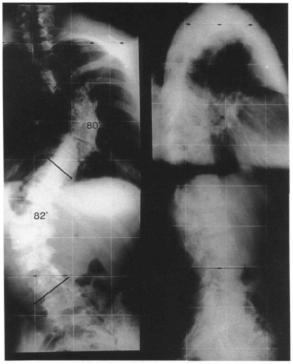
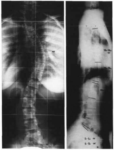
Fig. 8.147 Plain radiographs of the spine in two planes, obtained with the patient standing. The images show a 14-year-old female patient with idiopathic adolescent right convex thoracic scoliosis, type II according to King. At 48°, according to Cobb, the right convex curve is more pronounced than the left convex lumbar curve of 28°. The lateral radiograph shows the typical flattened thoracic spine of thoracic lordoscoliosis with lordosis between T4 and T12, measuring −20° according to Cobb, accompanied by flattening of the lumbar lordosis.
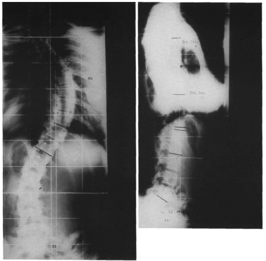
Table 8.35 Classification of the right convex thoracic curves according to King
| King type | Criteria | Incidence |
| Type I | Double curve scoliosis, in which the thoracic and lumbar curves both cross the midline. The lumbar curve is larger and more rigid than the thoracic curve. “Genuine” double curve scoliosis | 13% |
| Type II | Double curve scoliosis, in which the thoracic and lumbar curves both cross the midline. The thoracic curve is larger and more rigid than the lumbar curve. “False” double curve scoliosis | 33% |
| Type III | Thoracic scoliosis in which the secondary lumbar does not cross the midline | 33% |
| Type IV | Thoracic scoliosis with a long curve. The second last lumbar vertebra is tilted | 9% |
| Type V | Double structural thoracic scoliosis with the first thoracic vertebra tilted along the convex superior curve (positive T1 tilt) | 12% |
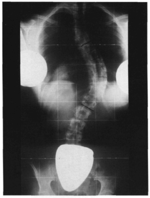
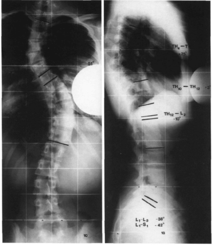
Fig. 8.150 Plain radiographs of the spine in two planes, obtained with the patient standing. The images show a 15-year-old female patient with idiopathic adolescent double-arc thoracic scoliosis, type V according to King, with positive T1 tilt. The lateral radiograph shows a largely physiologic profile.
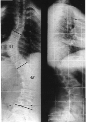
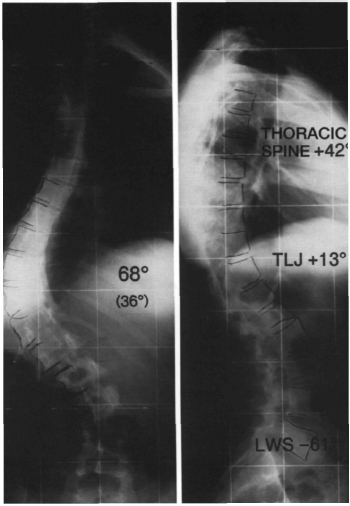
Fig. 8.152 Plain radiographs of the spine in two planes, obtained with the patient standing. The images show a 16-year-old female patient with idiopathic adolescent left convex low thoracic scoliosis measuring 68° according to Cobb. The lateral radiograph shows abnormal low thoracic kyphosis with kyphosis of the thoracolumbar junction measuring +13° according to Cobb.
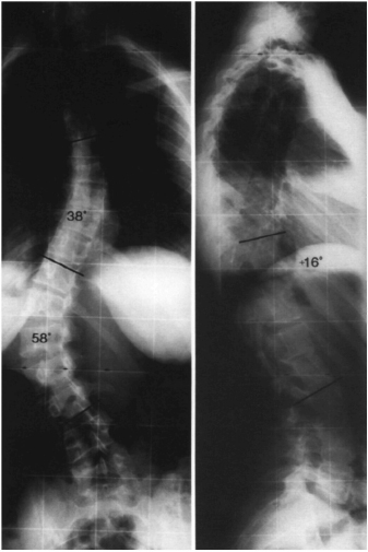
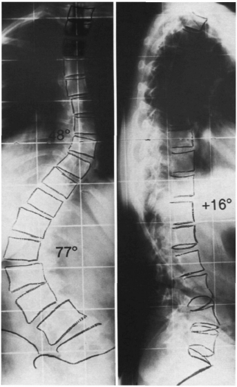
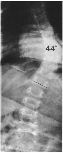
Fig. 8.155 Plain radiograph of the spine in the coronal plane, obtained with the patient supine. The images show infantile right convex thoracic scoliosis measuring 44° according to Cobb in a 2-year-old boy.
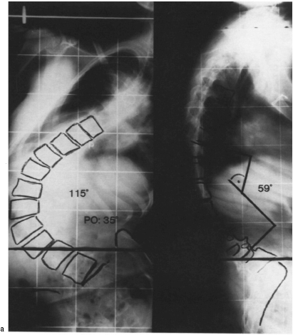
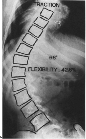
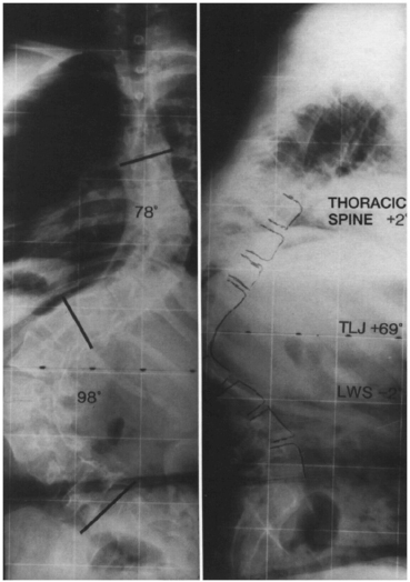
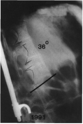
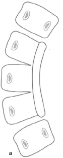
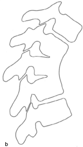
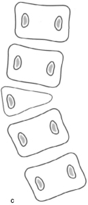
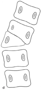
Figs. 8.159a–d Examples of segmentation failure in the spinal column. (a) Unilateral unsegmented bar. Progressive scoliosis will result. (b) Anterior segmentation failure. Progressive kyphosis will result (Fig. 8.171, see p. 371). (c) Segmented hemivertebra with scoliosis. (d) Nonsegmented hemivertebra with scoliosis.
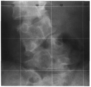
Fig. 8.160 Plain radiograph of the lumbar spine in the coronal plane. The image shows a segmented hemivertebra on the right side and a nonsegmented hemivertebra on the left side (corresponding to Figs. 8.217a, b, p. 396).
According to the age at which the deformity occurs, scoliosis is referred to as infantile (up to age 3 years) (Fig. 8.155), juvenile (age 4–10 years), or adolescent (age 11 years until completion of growth).
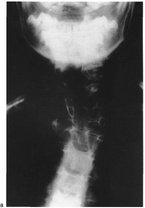
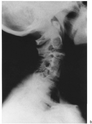
There are three major categories of adult scoliosis:
– Young adults with previous scoliosis no degenerative changes.
– Older adults with previous scoliosis now with superimposed degenerative changes.
– Older adults with degenerative scoliosis where there is no evidence of scoliosis before the age of 40 (de-novo scoliosis).
• Radiographic studies
The AP radiograph should be obtained as a radiograph of the entire spinal column, including the entire cervical spine and pelvis, with the patient standing. In this projection, scoliosis is discernible from the lateral curve that is measured using the Cobb angle. To do this it is necessary to locate the respective neutral vertebrae that mark the transition from convexity to concavity and to determine the angle between the superior end-plate of the superior neutral vertebra and the inferior end-plate of the inferior neutral vertebra (Fig. 8.162).
Rotation, according to the method described by Nash and Moe (1969), is the deviation of the convex pedicle from the concavity. The percentage of shift within the width of the vertebral body corresponds to the rotation in degrees (Fig. 8.163). An alternative method to measure vertebral rotation is the method according to Perdriolle (Perdriolle 1981). A deviation from vertical, which is frequently observed, can be measured in centimeters by drawing a vertical line from C7 and measuring the deviation of the spinous process of S1. Aside from this, pelvic or sacral obliquity must be excluded because this is closely related to scoliosis.
Bending views are useful in the treatment of scoliosis. These are obtained by positioning the patient supine and instructing him or her bend to each side. They differentiate between structural and flexible components of the curve (Figs. 8.164a, b).
Every scoliosis patient should have a full-length lateral radiograph to permit evaluation of the extent of sagittal profile abnormalities, which are frequently present. Thoracic scoliosis will frequently be associated with thoracic hypokyphosis (known as lordoscoliosis), and thoraculumbar scoliosis will frequently be associated with pathologic kyphosis of the thoracolumbar junction. In the full-length radiograph, the vertical line may be drawn from the opening of the external acoustic meatus. Normally, the axis will run through the anterior column (Lewit 1977).
Whenever a spinal deformity is present in children, skeletal age should be determined to evaluate remaining growth and the risk of curve progression. Recommended methods include evaluation of the apophyses of the iliac crests according to Risser (see chapter 9, p. 438) which is often possible using the full-spine AP radiograph (Fig. 8.165 and Table 9.7) or Greulich and Pyle’s method of determining skeletal age using a radiograph of the left hand (Table 8.36).
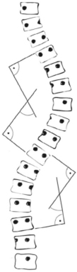
Fig. 8.162 Schematic diagram for measuring scoliosis according to Cobb.
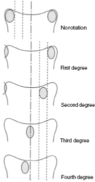
Fig. 8.163 Schematic diagram for determining rotation of a vertebral body according to Nash and Moe.
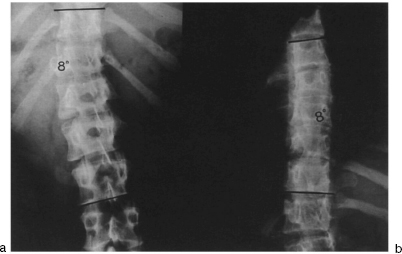
Figs. 8.164a, b Plain radiograph of the thoracolumbar spine in the coronal plane. Bending views obtained with the patient supine show a left convex thoracolumbar scoliosis. At maximum left bending, the thoracolumbar curve is seen to straighten to 8° according to Cobb (a). The secondary right convex thoracic curve is also seen to straighten to 8° according to Cobb when the patient bends maximally to the right (b).
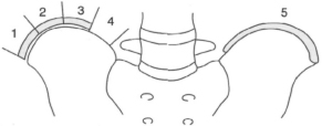
Fig. 8.165 Schematic diagram of the Risser sign for determining skeletal age. At Risser I, the radiograph shows the onset of ossification of the apophysis of the iliac crest. At Risser V, ossification is complete (Table 9.7, see p. 439).
Kyphosis
Isolated changes occur particularly as hyperkyphosis of the thoracic spine with Cobb angles exceeding 40°. Adolescent kyphosis, or Scheuermann disease, is a clinically significant idiopathic form (Figs. 8.20, 8.21, p. 302). The cause of this disorder is controversial, but it primarily involves the thoracic spine. Typical radio-logic changes with Scheuermann disease include:
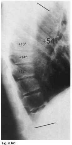
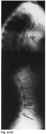
Fig. 8.167 Plain lateral radiograph of the spine. The image shows Scheuermann disease with thoracic kyphosis measuring 76°.
| View | Radiographic measuring param eters |
| Full-spine AP | Cobb angle |
| radiograph | Rotation |
| Deviation from vertical in coronal | |
| plane | |
| Shoulder position | |
| Pelvis position | |
| Risser sign | |
| Full-spine lateral | Thoracic kyphosis |
| radiograph | Thoracolumbar spine |
| Lumbar lordosis | |
| Deviation from vertical in sagittal | |
| plane | |
| Bending views | Cobb angle |
| Left hand AP | Skeletal age |
| radiograph |
– Schmorl nodes
– Irregular vertebral end-plates
– Pronounced narrowing of the intervertebral sections
– Three or more adjacent vertebrae with 5° or more of anterior wedging
– Thoracic hyperkyphosis of more than 45° (Figs. 8.166 and 8.167).
There is also a lumbar form of the disease.
Ankylosing spondylitis is a rheumatic disorder that primarily affects the synovial joints of the spinal column, neighboring soft tissues, and the sacroiliac joints. Ossification that shortens the anterior longitudinal ligament, accompanied by formation of syndesmophytes, leads to kyphotic deformities involving the entire spine. Different types of kyphosis can result, depending on the pattern of involvement (Figs. 8.168a–e). The disease often emanates from the sacroiliac joints, which in the plain radiograph simultaneously show signs of erosion, sclerosis, and ankylosis (Krämer et al. 1993). Involvement of the spinal column progresses superiorly during the course of the disease. The disorder is characterized by rectangular vertebrae, resulting from erosion of the normally biconcave vertebral end-plates and the typical syndesmophytes. The syndesmophytes tend to be aligned more vertically than degenerative spondylophytes and have a finer appearance. Increasing ossification of the facet joints as the disease progresses leads to a typical “railroad sign” in the AP radiograph, which can appear to have three tracks as the ossification of the interspinal ligaments progresses (Fig. 8.169). In the final stage of the disease, complete ossification of the apophyseal joints will give the spinal column an appearance referred to as “bamboo spine.” The pathologic ossification can be classified according to surgically relevant criteria (Fig. 8.170) (Hehne and Zielke 1990).
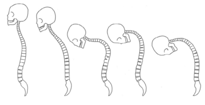
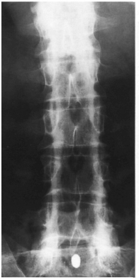
Fig. 8.169 Plain AP radiograph of the lumbar spine. The image shows the “railroad sign” of ankylosing spondylitis. Only the facet joints are affected.
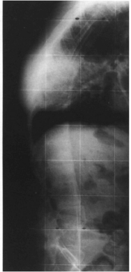
Fig. 8.170 Plain lateral radiograph of ankylosing spondylitis.
A secondary kyphosis is generally characterized by a short arc, i.e., a gibbus. It can occur as the result of trauma, infection, or tumor, but may also be a result of congenital deficiencies (Fig. 8.171).
Vertebral Arch Defects
Failure of fusion of the vertebral arches represents the most frequent congenital deformity of the spinal column. These range from harmless spina bifida occulta, a variation of the normal spine, to meningomyelocele or myelocele, which involve symptoms typical of a transverse lesion. Common sites include the lumbar spine and the lumbosacral spine, although the atlas can be affected in rare cases. Spina bifida occulta is the result of incomplete bony fusion of the vertebral arches in a closed cartilaginous spinal canal in which the neural structures are usually intact. Spina bifida cystica involves prolapse of the arachnoid with either a normal spinal cord (meningocele) or involvement of the spinal cord (meningomyelocele; Figs. 8.172a–d). Both forms are usually associated with sensorimotor transverse paralysis at the level of the bony defect. Spina bifida aperta is the most serious form of fusion failure of the vertebral arches since the spinal cord is exposed without a layer of covering skin. Failure of fusion of the vertebral arches is recognizable in the plain AP radiographs by the respective defect (Figs. 8.173a, b and 8.174). CT or MR studies may be performed to further determine the extent of the disorder.
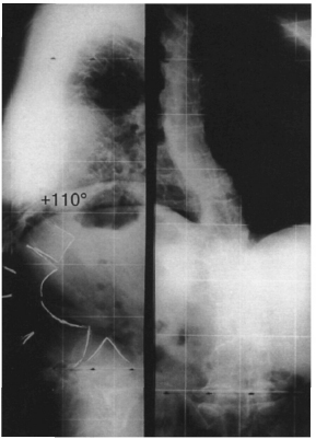
Fig. 8.171 Plain radiograph of the spine in two planes. The image shows congenital kyphosis with anterior failure of segmentation (see Fig. 8.159, page 366).
Osteoporotic Changes in the Spine
Osteoporosis is characterized by a quantitative decrease in the bone matrix, i.e., a decrease in both the organic and mineral content of the bone tissue. In the plain radiograph, this is seen as an increase in radiolucency, although this phenomenon will only be discernible once the decrease in bone matrix has exceeded 30% (MacNab 1971). The cancellous trabeculae are rarefied and the cortex narrowed. In the spine these changes will be most apparent in the cancellous vertebral bodies. Since the cancellous parts of the vertebra are affected first, it will appear on the radiograph as a hollow vertebra due to the relative increase in density of the cortex. During the further course of the disease, the thinned end-plates of the vertebrae can collapse under the intervertebral disk tissue, producing biconcave vertebral deformities known as fish vertebrae. Further subsidence of the anterior and posterior margins of the vertebral body lead to flattening of the vertebrae. In its advanced stages, osteoporosis is characterized by multilevel compression fractures that result in wedge-shaped vertebrae (Figs. 8.175a, b).
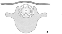
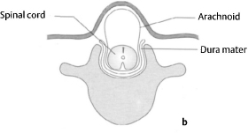
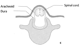
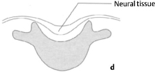
Figs. 8.172a–d Schematic diagram of various types of failure of fusion of the vertebral arches.
(a) Spina bifida occulta: incomplete bony fusion of the vertebral arches without displacement of the spinal cord or the meninges.
(b) Meningocele: displacement of the meninges without displacement of the spinal cord and with a bony defect of the vertebral arch.
(c) Meningomyelocele: displacement of the spinal cord and the meninges through the bony defect of the vertebral arch. The neural structures are either covered by skin or exposed.
(d) Spina bifida aperta (rachischisis): embryologie failure of fusion of the neural tube with exposure of neural tissue at the surface.
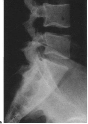
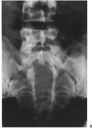
Figs. 8.173a, b Plain radiograph of the lumbosacral spine in two planes showing sacral spina bifida.
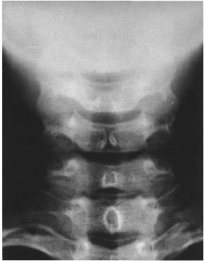
Fig. 8.174 Plain Ap radiograph of the cervical spine. The image shows spina bifida occulta of the sixth cervical vertebra.
Table 8.37 Overview of the processes used to measure bone density
• Single and dual photon absorptiometry
• Single and dual X-ray absorptiometry
• Quantitative CT


Stay updated, free articles. Join our Telegram channel

Full access? Get Clinical Tree


