Fig. 20.1
Spinal Loading System. (a) Patient in upright normal position on the load platform for a routine anteroposterior radiograph. (b) The frictionless rotating mechanism rotated clockwise by degrees. The direction of the rotation is determined according to the deformity patterns of the patient’s spine (Reproduced from Elias de Oliveira [15] with permission)
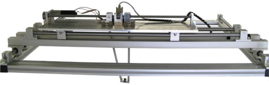
Fig. 20.2
Three degrees-of-freedom mechanism capable of applying a pure axial mechanical load to the patient’s cervical spine (Reproduced from Elias de Oliveira [15] with permission)
The SLS is equipped with a motion controller driver (MCLM 3006, Faulhaber Minimotor SA, Switzerland); a DC-servomotor (2642W012CR, Faulhaber Minimotor SA, Germany) with integrated precision gearbox 26/1(S) 66:1 and encoder; and a load platform Nintendo Wii balance board (Nintendo, Kyoto, Japan). The considered load platform is a low-cost bluetooth-operated device composed of four calibrated strain-gauges, and it has been proven to be accurate and suitable for clinical research [16].
Control logic provides the SLS with closed-loop position control dependent of the patient’s body weight (BW) percentage reduced by applying a quasi-static tractive force to the patient’s cervical spine, which is computer-controlled via an RS232 serial port. A software with a friendly graphical user interface (GUI) was developed as shown in Fig. 20.3. The software was written in ANSI/ISO C++ and developed on ×86 GNU/Linux systems with GNU C Compiler (GCC) 4.3.3, libcwiid, Qt and VTK. Patient’s information and experimental data such as time stamp in milliseconds, force distribution in the four individual strain-gauge sensors type, center of the resulting force, and strains rates are stored in ASCII format for further offline data analysis. The SLS has the advantage of being easily combined with conventional X-ray devices, since its a portable modular assembly system, adjustable, and lightweight, as shown in Figs. 20.1 and 20.4.
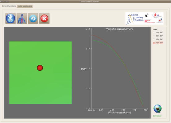
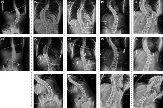
Fig. 20.3
Spinal Loading System intuitive control interface. Calibration procedure assuming the human spine as a spring-like structure. Left: Phantom’s center of mass. Right: Displacement-released weight curve. The red and green curves represent the loading and unloading conditions, respectively. The load shift between these curves is explained by the initial positioning of the designed mechanism for application of pure axial loads (Reproduced from Elias de Oliveira [15] with permission)
Fig. 20.4
Cobb angle measurements. First row: anteroposterior radiographs in normal upright position. Second row: Pure axial quasi-statistic tractive load corresponding to 30 % of the patient’s body weight generated by the proposed SLS. Third row: Lateral bending posteroanterior radiographs. It is important to note that the patient P1 did not perform the lateral bending test and, therefore, could not be included in this study (Reproduced from Elias de Oliveira [15] with permission)
Data Acquisition
Before the evaluation of the proposed preoperative method for assessing the curve flexibility in AIS was started, a preoperative radiologic evaluation using the widely accepted side bending technique has been performed.
Consequently, a standard commercial cervical traction head halter commonly used in physiotherapy treatment (Basler Orthopädie Renè Ruepp AG, Basel, Switzerland) has been used to ensure the application of the forces directly to the patient’s spinal column. The head halter components were gently placed on the posterior portion of the head (occiput) and on the lowermost part of the face (chin), as shown in Fig. 20.1.
The patients were asked to stand in upright normal position in the SLS working space and were instructed to relax the group of abdominal, back, and neck muscles and not to move between consecutive anteroposterior and lateral radiographs. A preload tractive force corresponding to 5 % of the patient’s body weight was applied to positioning the three degrees of freedom slider component in the patient’s location. Anteroposterior and lateral radiographs of the lumbar and thoracic spines were acquired in the unloaded condition. Lateral radiographs were acquired by rotating the patient around its own axis on the frictionless platform by 90° according to the deformity pattern of the patient’s spine.
The SLS software was initialized, and the actual patient’s body weight was registered for determination of the stop-criterion. Loads acting vertically upward with magnitudes determined from the previously measured patient’s body weight (BW) were applied. The quasi-static tractive forces were applied stepwise from 10 % BW to 30 % BW in 10 % BW step. After the stop-criterion was reached, additional coronal and sagittal radiographs of the patient’s spine were acquired under loaded conditions. The patients were monitored by the medical staff members during the application of the quasi-static tractive forces and were continuously instructed to relax all group of muscles associated with posture and balance.
The resulting loads, forces distribution on the four individual strain-gauge sensors, patient’s center of mass, and strain-rates were continuously acquired at a sampling frequency of 15 Hz and stored in ASCII format for post-processing.
Finally, the software tool developed by [17] has been used to assess the Cobb angles of the structural curves in all considered conditions, i.e., normal upright position, side bending, and under the application of a pure axial quasi-static load, and their respective curve flexibilities have been computed.
Results
To assess the amount of correction of the structural curves achieved by the lateral bending technique and by the proposed SLS, the Cobb angles measured from lateral bending and SLS radiographs were subtracted from their respective Cobb angles measured on radiographs acquired on normal upright positions. The mean Cobb angle in normal upright position measured 58.85° (range, 45.88–71.21°). Average curve flexibility was 29.87° (range, 16.86–45.40°) on lateral bending, and 12.60° (range, 4.54–27.66°) on the application of a pure axial quasi-static tractive load corresponding to 30 % of the patient’s body weight. The average final applied load was 16.45 Kg, ranging from 14.43 to 17.79 Kg. The Table 20.1 summarizes the spinal deformities characteristics, patients’ information, curves reduction for both techniques, and determined magnitude of the quasi-static tractive load as a function of the patient’s body weight.
Table 20.1
Spinal deformities characteristics and patient’s general information
Case | Age | Apex | BMI | Load | Cobb angle [degrees] | ||
|---|---|---|---|---|---|---|---|
[Kg] | NUP | SLS | LB | ||||
P1
Related posts: Virtual Preoperative Planning Virtual Preoperative Planning
 Computational Image-Guided Technologies in Cranio-Maxillofacial Soft Tissue Planning and Simulation Computational Image-Guided Technologies in Cranio-Maxillofacial Soft Tissue Planning and Simulation
 Patient-Specific Instruments in Orthopedics Patient-Specific Instruments in Orthopedics
 Virtual Cranio-Maxillofacial Surgery Planning with Stereo Graphics and Haptics Virtual Cranio-Maxillofacial Surgery Planning with Stereo Graphics and Haptics
 Navigation in Spinal Surgery Navigation in Spinal Surgery
 3D Projection-Based Navigation 3D Projection-Based Navigation
Stay updated, free articles. Join our Telegram channel
Full access? Get Clinical Tree
 Get Clinical Tree app for offline access

| |||||||