Fig. 4.1
Arthroscopic view through the anterolateral portal of an elongated SB vertical autograft with a high notch roof femoral tunnel aperture
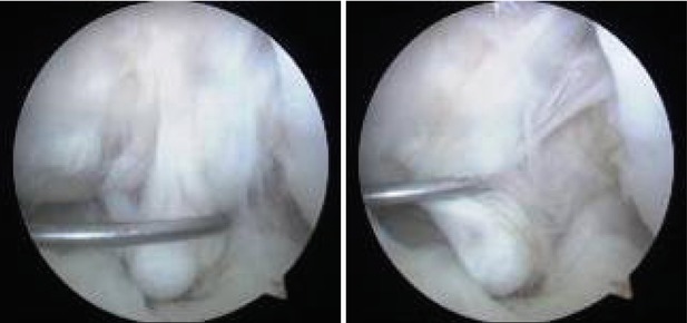
Fig. 4.2
Arthroscopic view through the anterolateral portal of a very elongated, insufficient SB vertical hamstrings autograft, 1 year after reconstruction in a young female handball player
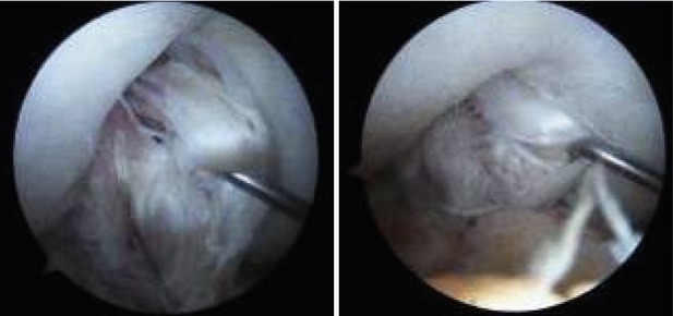
Fig. 4.3
Arthroscopic view through the anterolateral portal of an elongated, insufficient DB hamstrings autograft 1 year after reconstruction in a professional soccer player
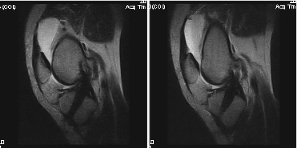
Fig. 4.4
Sagittal T2 MRI 5 years after anatomic SB ACL reconstruction with ipsilateral hamstrings autograft showing a homogenic hypointense aspect of the neoligament with a hyperintense femoral insertion suggestive of partial proximal rupture
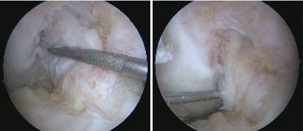
Fig. 4.5
Arthroscopic views of the same case through the anterolateral and anteromedial portals respectively showing a healed and integrated graft; the arthroscopic evaluation was performed in order to perform a partial medial meniscectomy resulting from a recent noncontact sporting injury
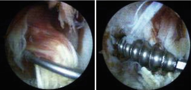
Fig. 4.6
Arthroscopic views through the anterolateral portal showing an elongated, insufficient patellar tendon autograft at the time of revision, 5 years after index surgery; removal of the misplaced metallic femoral interference screw (Fig. 4.18)
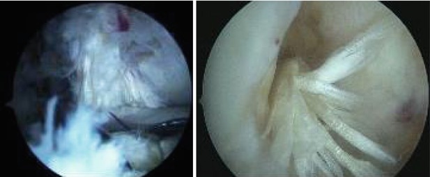
Fig. 4.7
Arthroscopic view of the same case through the anterolateral portal showing the placement of the tibial tunnel aperture at the time of revision; 3 years afterwards, the patient has a midruptured ipsilateral hamstrings autograft (Fig. 4.20)
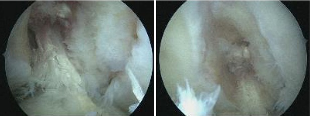
Fig. 4.8
Arthroscopic views of the same case through the anterolateral and anteromedial portals respectively after debridement; the arthroscopic evaluation was performed in order to remove a loose body (a fragment of the femoral biodegradable interference screw)
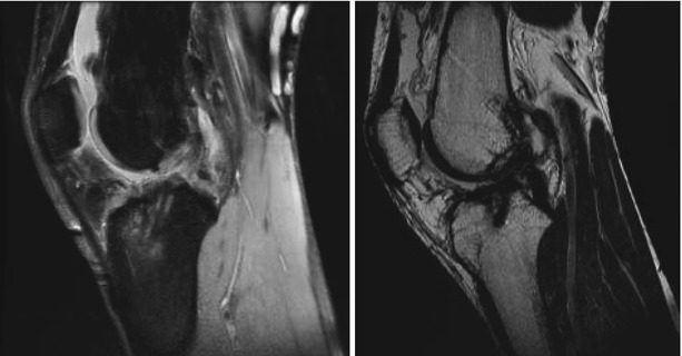
Fig. 4.9
Sagittal PD and T2 MRI of a failed vertical neoligament with distal rupture
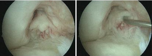
Fig. 4.10
Arthroscopic views of the same case through the anterolateral portal showing a distally ruptured graft; the arthroscopic evaluation was performed in order to perform a partial meniscectomy resulting from a recent injury
The current trend towards anatomic ACL reconstructions has had a somewhat contradicting situation identified in the Danish Knee Ligament Reconstruction Register, where the use of the anteromedial portal technique increased from 13 % in 2007 to 40 % in 2010. This procedure, aimed at improving placement of the graft was found to have a two to three fold increase in relative risk of revision, sagittal instability and positive pivot shift compared with the older transtibial technique (TT). The authors potentially explain these findings through technical failures from introduction of a new technique or by the higher forces that anatomic placed grafts withstand compared to vertical ones [29]. This leads us to underline that anatomic placement of the graft requires careful analysis of the landmarks and that merely anteromedial drilling of the femoral tunnel might not suffice.
4.4 Assessment of Bone Tunnels
Inappropriate tunnel positioning or new trauma account for the majority of cases planned for revision ACL surgery. This leads to different situations for the placement of the new apertures. Standard x-rays are not able to satisfactorily give information regarding the location, size and bone quality in order to adequately perform the preoperative planning. Therefore, the standard imaging modality is now considered computed tomography (CT) with 3D (three dimensional) volume rendering (reconstruction) [30] (Figs. 4.11 and 4.12). The CT also demonstrated excellent intra- and inter-observer reliability compared to plain x-ray and MRI [31].

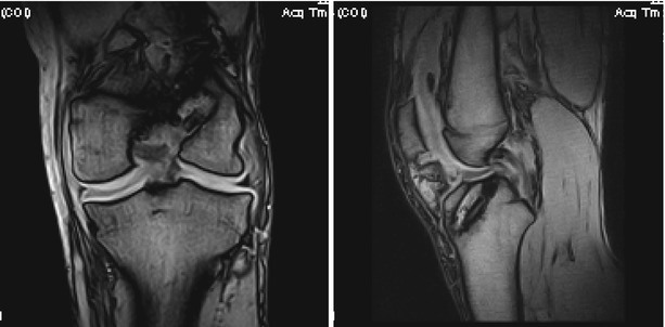

Fig. 4.11
Sagittal CT and T1 and T2 Gradient Echo MRI aspects of tibial tunnel enlargement following ACL reconstruction

Fig. 4.12
Coronal and sagittal frequency-encoding gradient (GFE) T1 MRI scan of a patient with failed ACL reconstruction and significant tunnel enlargement; bioabsorbable screw fragments are visible in both tunnels
In addition, the tunnels might also be enlarged and might require graft filling prior to the new reconstruction. Tunnel expansion has been shown to occur predominantly during the first months after surgery, as the bone-tendon interface is more active [32]. However, in the setting of failure to integrate, this process can continue and might be irreversible spontaneously within a reasonable timeframe before revision (Figs. 4.13, 4.14, and 4.15).
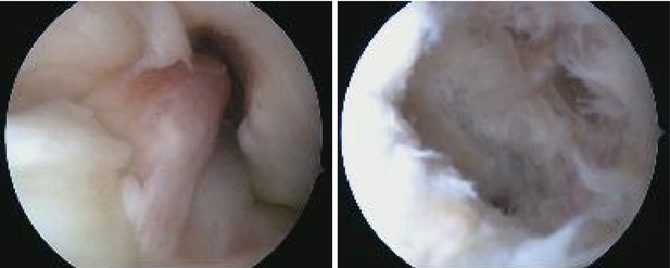
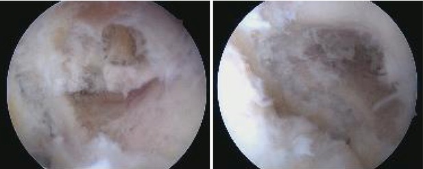
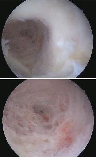

Fig. 4.13
Arthroscopic views of the same case through the anterolateral and anteromedial portals respectively showing a complete proximal discontinuity of the graft, before and after debridement

Fig. 4.14
Arthroscopic views of the same case through the anteromedial portal depicting an enlarged but well positioned femoral tunnel aperture

Fig. 4.15
Arthroscopic views of the same case through the anteromedial portal with additional close-up of the femoral tunnel bone structure
When the revision plan is to drill entirely new tunnels, care should be taken to ensure a strong enough bridge between the two. It has been shown that a minimum of 2 mm are required to provide structural stability, which is of particular interest in revision cases, double bundle reconstruction and small knees. In addition, cortical buttons provide superior strength compared to aperture fixation when multiple tunnels are drilled through the lateral femoral condyle [33]. Clock dial, quadrant and anatomic insertion references are used to describe the location of the tunnel apertures [34] and more recently even a proposed standardized 3D CT evaluation of femoral tunnel based on the relationship of the aperture to the lateral intercondylar ridge [35].
The revision ACL reconstruction should not be a planned as a salvage procedure and all efforts should be put into restoring the native function and anatomy. In the MARS study, the most common technique for both index and revision procedures was arthroscopic single-incision transtibial drilling. Bone grafting of dilated tunnels was uncommon (3 %) and rarely performed as a two staged procedure. Unfortunately the prevalence of cartilage or meniscal damage was very high (70 %) [7]. A similar situation was identified by a systematic review. At the time of revision half of patients underwent a meniscectomy and. 15 % a repair, and more than half had chondral damage [8]. The community based register report of Maletis et al. noted cartilage damage in more than one-third of revision procedures and meniscal lesions in more than half respectively. Fixation distribution was similar for primary and revisions with a preponderance use of interference screws [2].
4.5 Graft Choices
There are only few differences between graft choice rationale in revisions compared to primary reconstructions. The clinical outcome does not appear to be influenced by graft type [37]. Most commonly the graft choice is determined by what was previously used and the surgeon’s preference [7]. Bone patellar tendon bone (B-PT-B) autograft is generally the most commonly used [7, 8, 14, 36]. It has the potential to aid with filling of bone tunnel enlargement when the same tunnel is used.
In the MARS cohort, previous grafts were 70 % autologus and 27 % allograft. Choices for revisions were 45 % auto and 54 % allograft [7]. A systematic review reported the index graft material to be 86.1 % autologus, 5.5 % allograft and 8.5 % synthetic. For revisions, there was a slight increase in the use of autografts 89.4 %. These were mainly B-PT-B (48 %) followed by hamstrings (40 %) and quadriceps tendon (12 %) [8]. Similar data was presented by Trojani et al. with the use for revision of predominantly B-PT-B (50 %) followed by hamstrings (40 %) and quadriceps tendon (10 %). Initial B-PT-B was revised by either B-PT-B (ipsi or contralateral, 45 %), by an ipsilateral hamstrings in 45 % and by quadriceps tendonin 10 %. Primary hamstrings were revised by ipsilateral B-PT-B in 67 %, the contralateral hamstring in 24 % and quadriceps tendonin 9 % [14].
There are also surgeons who prefer either unharvested ipsilateral hamstrings or B-PT-B or Achilles allografts [37]. The contralateral hamstrings [39] or the ipsilateral quadriceps tendon [41] are also options without increased donor site morbidity. Centers with routine use of allografts in primary procedures (42.4 %) tend to also favor them for revisions (78.8 %) [2]. Results with allografts that had not undergone irradiation or chemical sterilization appear to be comparable to those with autografts [38].
4.6 Previous Non Anatomic Placement
At least for now, this is the most common situation for revision. In the presence of improperly positioned tunnels without significant enlargement, the revision allows for new tunnels to be drilled, making it similar to a primary procedure. When the SB femoral tunnel is placed high in the notch, even DB revision reconstruction can be successfully performed [42]. The reverse can also be used. If both initial DB bundles are too anterior (posterolateral PL) and too high (anteromedial AM) there might be sufficient space on the posterior lateral condyle to perform an anatomic SB reconstruction.
Out of all possibilities for non anatomical graft placement, femoral tunnel malpositioning is the most common single cause (76.9 %). In the MARS cohort, this was further evaluated as being mainly too vertical (35.9 %), followed by too anterior (29.9 %) or both (26.5 %) [21]. This is mainly attributable to the transtibial (TT) drilling technique, which tends to place the tibial aperture too posterior and the femoral too anterior and superior, leading to a “vertical” aspect of the neoligament.
On the tibial side, aperture malpositioning varies from 29.7 % (MARS) [21] to 11 % [23] or as little as 6 % [22]. For these reasons, revision usually involves drilling an entirely new femoral with the same optimal tibial aperture (82.1 % and 51.3 % respectively in the MARS report by Morgan et al.) [21].
Case Example
A 25 years old male with elongated B-PT-B graft, bucket handle internal meniscus tear and grade II chondral damage of the medial compartment after a recent trauma. The patient had a history of giving way since index surgery. The clinical exam found antero-posterior instability and KT-1000 side to side difference of 10 mm. CT exam showed improper tunnel positioning (femoral vertical and anterior) and moderate tibial tunnel widening (Fig. 4.16). The sagittal MRI T2 was suggestive for an elongated graft. We performed a one stage revision: arthroscopic exploration, removal of the ruptured border of the internal meniscus, confirmation of the elongated graft and debridement (Fig. 4.17). Ipsilateral semitendinosus and gracilis were harvested and quadrupled into a size 7 neoligament. The new femoral tunnel was drilled in the anatomic footprint through the anteromedial portal. We then drilled a new tibial tunnel, medial to the previous, in the anatomic position (Figs. 4.18 and 4.19). Proper placement of the new ligament does not create notch or posterior cruciate ligament (PCL) impingement (Fig. 4.20). For fixation we used a cortical button for the femur and 9.30 absorbable (PLLA) interference screw on the tibia in 20° of flexion. Proper tunnel positioning can be seen on the postoperative X-rays (Fig. 4.21).
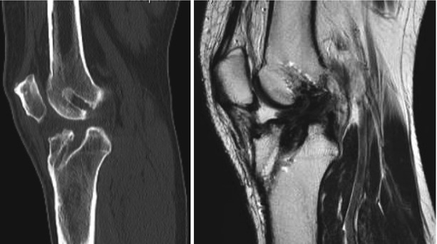
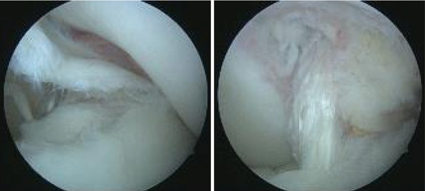
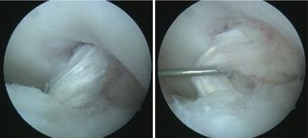
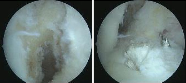
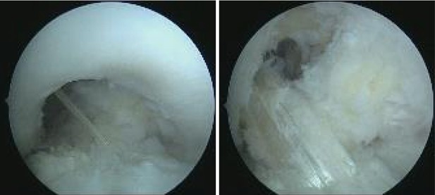
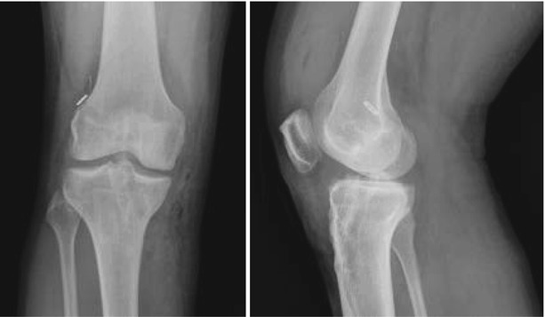

Fig. 4.16
Sagittal CT exam shows improper tunnel positioning (femoral vertical and anterior) and moderate tibial tunnel widening. The sagittal MRI T2 was suggestive for an elongated graft

Fig. 4.17
Arthroscopic views through the anteromedial portal showing the internal border of the medial meniscus dislocated in the notch and a vertical graft. a complete proximal discontinuity of the graft, before and after debridement

Fig. 4.18
Arthroscopic views through the anteromedial portal showing roof impingement and an insufficient and elongated graft

Fig. 4.19
Arthroscopic views through the anterolateral portal showing the correct position of the femoral and tibial apertures: lower and deeper on the lateral condyle and more medial on the tibia respectively

Fig. 4.20
Arthroscopic views through the anterolateral portal showing the correct position of the new ligament which does not create roof or posterior cruciate ligament (PCL) impingement

Fig. 4.21
AP (antero-posterior) and lateral postoperative X-rays showing adequate tunnel positioning
Case Example
A 25 years old male presents with elongated B-PT-B graft, extension deficit and grade II chondral damage of the medial compartment. The patient has initially torn his ACL 2 years before. The index reconstruction was performed using the transtibial (TT) technique. The sagittal MRI T2 was suggestive for an elongated graft and the patellar tendon showed signs of tendinitis (Fig. 4.22). The patient had a history of giving way since index surgery. The clinical exam found antero-posterior instability and KT-1000 side to side difference of 7 mm and 5° of extension deficit. CT exam showed improper tunnel positioning (femoral vertical and anterior) and minor tibial tunnel widening (Fig. 4.23). We performed one stage anatomic SB revision. Arthroscopic exploration confirmed the elongated graft with roof impingement and it was debrided wising a shaver and a punch (Fig. 4.24). Ipsilateral semitendinosus and gracilis were harvested and quadrupled into a size 7.5 neoligament. The new femoral tunnel was drilled in the anatomic footprint through the anteromedial portal. We then drilled a new tibial tunnel, more posterior to the previous, in the anatomic position (Fig. 4.25). For fixation we used a cortical button for the femur and 9.35 absorbable (PLLA) interference screw on the tibia in 20° of flexion. Proper placement of the new ligament does not create notch or posterior cruciate ligament (PCL) impingement (Fig. 4.26). Proper tunnel positioning can be seen on the postoperative X-rays (Fig. 4.27).
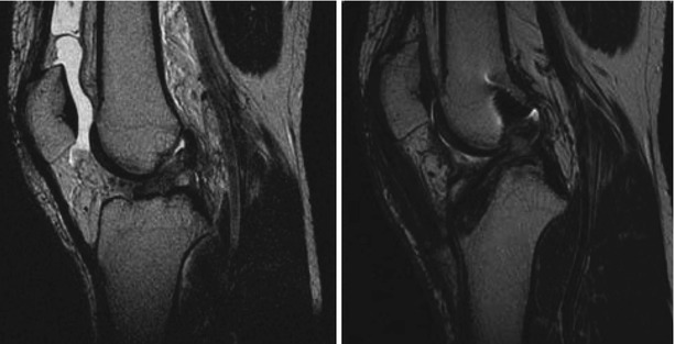
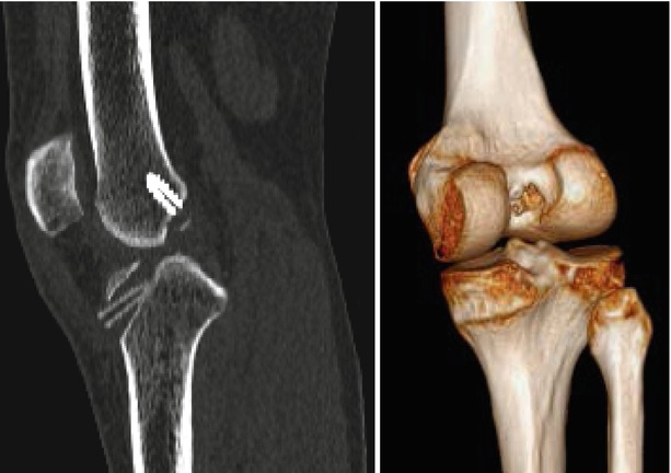
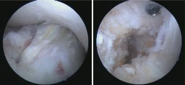
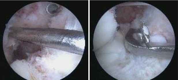
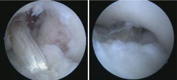
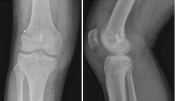

Fig. 4.22
Sagittal MRI T2 soon after the initial injury with a hyperintense, discontinued ACL in the proximal part; 1 year after index reconstruction, the MRI is suggestive for an elongated graft and the patellar tendon is thickened

Fig. 4.23
Sagittal CT exam and 3D volume rendering (posteromedial oblique view) showing improper tunnel positioning (femoral vertical and anterior) and minor tibial tunnel widening

Fig. 4.24
Arthroscopic exploration through the anteromedial portal confirms roof impingement and improper femoral aperture (high)

Fig. 4.25
Arthroscopic views through the anterolateral portal showing the correct position of the femoral and tibial apertures: lower and deeper on the lateral condyle and more posterior on the tibia respectively

Fig. 4.26
Arthroscopic views through the anterolateral and anteromedial portals respectively, showing the correct position of the new ligament which does not create PCL or roof impingement

Fig. 4.27
AP and lateral postoperative X-rays showing adequate tunnel positioning compared to the previous femoral tunnel
Case Example
A 30 years old male presented with bilateral ACL reconstructions using B-PT-B grafts and TT techniques. The sagittal MRI T2 of the left knee was suggestive for an elongated and vertical graft (Fig. 4.28). The patient had a history of giving way that was aggravated after a recent trauma. The clinical exam found antero-posterior instability and KT-1000 side to side difference of 3 mm. CT exam showed improper graft positioning (femoral vertical and anterior) and good tunnel bone filling. We performed one stage anatomic SB revision. Arthroscopic exploration confirmed the insufficient graft (Fig. 4.29). After debridement the medial and lateral compartments were explored (Figs. 4.30, 4.31, and 4.32). Ipsilateral semitendinosus and gracilis were harvested and quadrupled into a size 8 neoligament. The new femoral tunnel was drilled in the anatomic footprint through the anteromedial portal (Fig. 4.33). We then drilled a new tibial tunnel converging towards the same aperture. For fixation we used a cortical button for the femur and 9.35 absorbable (PLLA) interference screw on the tibia in 20° of flexion. Proper placement of the new ligament does not create notch or PCL impingement (Fig. 4.34). Proper tunnel positioning can be seen on the postoperative CT and X-rays (Fig. 4.35).

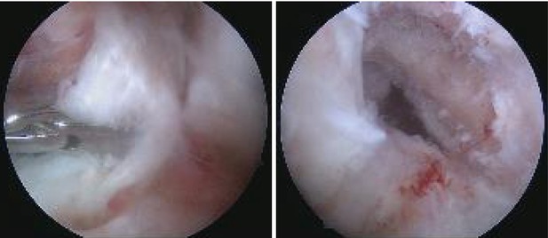

Fig. 4.28
The sagittal MRI T2 of the left knee was suggestive for an elongated and vertical graft

Fig. 4.29


Arthroscopic exploration through the antero lateral and anteromedial portals confirmed the insufficient graft
Stay updated, free articles. Join our Telegram channel

Full access? Get Clinical Tree


