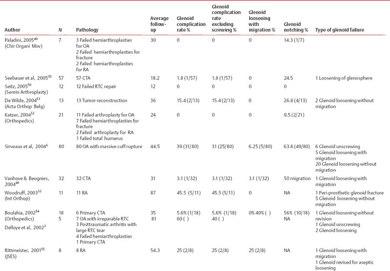
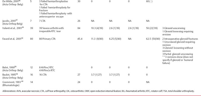
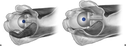
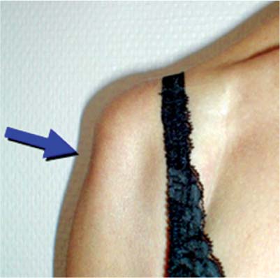
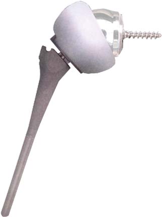
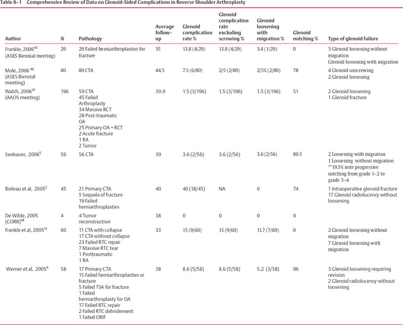
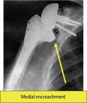
8 Rationale and Biomechanics of the Reverse Shoulder Prosthesis: The American Experience The design of reverse shoulder replacement has undergone several modifications since its original inception. Early versions of the reverse shoulder design (Fenlin, Gerard, Kessel, Kölbel, Liverpool, Neer, and Avery II) likely failed as a result of their inability to withstand the forces during normal shoulder function.1–7 The two most widely used reverse shoulder arthroplasty (RSA) designs today are the Grammont design (manufactured by both DePuy Orthopaedics, Inc., Warsaw, IN, and Tornier, Inc., Eden Prairie, MN) and the Reverse Shoulder Prosthesis (RSP; Encore Medical Corp., Austin, TX). The initial version of the Grammont reverse shoulder design, released in 1985, utilized two cemented components. Subsequently, modifications of this initial design have been made based on clinical experience. The current Grammont reverse design consists of a five-part system that utilizes a medialized center of rotation (COR) (Fig. 8–1). The glenosphere is a true hemisphere, with the COR directly in contact with the glenoid surface.2 Although the Grammont design has shown improvement in patient outcomes, several limitations have been reported.2–4 Four limitations noted most commonly by having the COR medially to the glenoid surface are 1. Scapula Notching Scapular notching has been documented by many patient series using the Grammont design and has ranged from 24.5 to 96% (Table 8–1).2,4–15 It is thought that notching is caused by impingement of the medial aspect of the polyethylene socket on the inferior portion of the scapular neck (Fig. 8–2).2 Although the long-term clinical significance of scapular notching remains a question, osteolysis and progressive erosion of the inferior scapula have been documented.5–7 As noted by Delloye et al,3 progressive scapular notching may be of considerable concern as it may result in late glenoid-sided mechanical failures (Fig. 8–3). Osteolysis in a joint with a well-fixed implant is a potentially devastating problem due to the substantial bone loss that may be associated with failure of that device. The biologic reaction from mechanical abrasion of polyethylene to aggressive bone resorption probably occurs when metal particles are released when the polyethylene liner is abraded and the metal liner is exposed.8,9 This process may be accelerated if a screw from the glenoid component is exposed from scapular bone loss and abrades with the metal shell. 2. Limited Range of Motion Currently, several different prosthetic designs of the reversed shoulder arthroplasties are available in a variety of geometries (notably, glenosphere size and COR). Differences in range of motion (ROM), stability, security of fixation, and motor function may vary greatly among the different implant geometries; hence the selection of the appropriate shoulder prosthesis requires a priori understanding of the implant geometry. From a clinical standpoint, maximizing the potential ROM is a key element for functional gains that may be achieved with reverse shoulder prosthetic designs. Centers of rotation that are farther away from the scapula allow the proximal humerus and humeral socket more clearance before impinging on the acromion or superior glenoid, thus maximizing glenohumeral abduction. In adduction, a more lateral COR ensures that the medial neck of the prosthesis does not impinge on the inferior aspect of the scapula. Figure 8–1 The current Grammont reverse design consists of a five-part system that utilizes a medialized center of rotation. Figure 8–2 Scapular notching caused by impingement of the inferior glenoid on the medial portion of the humeral socket. 3. Loss of Rotational Strength As the glenohumeral joint becomes more medialized, the length-tension relationship of the shoulder muscles changes (Fig. 8-4). The rotator cuff thus becomes relaxed, resulting in rotational weakness. This has been demonstrated clinically in reports using the Grammont design, because patients do not recover external rotation strength.4,10 4. Loss of the Deltoid Contour As a direct result of medializing the COR, the Grammont design results in a loss of the deltoid contour (Fig. 8–5). Aside from cosmetic concerns, loss of the deltoid contour may be indicative of significant effects on the deltoid function and strength, as well as joint stability. As the glenohumeral joint is medialized, the pulley effect of the deltoid is lost,11 and the added stability created by compressive forces of the deltoid on the joint becomes diminished. The RSP was inspired by the Grammont design, but with the advantages of keeping the COR lateral to the glenoid, as it is in the normal shoulder.12 Similar to the Grammont design, the RSP has also evolved since its initial use in 1998. The first published clinical study using the RSP design revealed significantly improved postoperative pain and functional outcomes.13 This study utilized the earliest version of the RSP, and some complications were thought to be related to prosthetic design. To understand why these complications occurred, biomechanical characteristics of the RSP were studied. In this chapter, I summarize the findings related to the biomechanics of the RSP and describe how these findings have been used to make improvements in prosthetic design. Numerous relevant studies are presented in abstract form with commentary throughout the chapter to illustrate more fully the biomechanical issues related to RSP. When the RSP was first designed (Fig. 8–6), it consisted of four parts with two glenosphere choices: a 32-mm neutral glenosphere with a COR 10-mm outside the glenoid and a 32 – 4 mm glenosphere with a COR 6-mm outside the glenoid. The glenosphere was attached to the glenoid via a baseplate that was fixed to the glenoid bone with a 6.5-mm central cancellous bone screw and four peripheral, variable angle, nonlocking, 3.5-mm diameter screws. On the humeral side, a cemented titanium stem articulated with the glenosphere via a conforming polyethylene component. The polyethylene component was attached to a Morse taper using a screw-in system and the Morse taper was locked into the humeral stem. Complications that occurred during the clinical use of the RSP prompted several design changes that have modified this initial design into what it is today. The primary reason for providing a choice of two glenospheres with CORs outside the glenoid was to minimize inferior scapular notching, which has been seen in many patient series using reverse designs with a more medial COR (Table 8–2).2,4–15 Other goals for placing the COR more lateral in relation to the glenoid were to obtain a more anatomic COR for the shoulder, to improve rotational strength, maximize glenohumeral motion, and to restore the deltoid contour. Nonetheless, many shoulder surgeons have reservations about using a more lateral COR with the reverse shoulder design. Past designs where the COR was lateral to the glenoid failed because their design resulted in excessive torque or shear forces on the glenoid component.2 For example, the Kessel reverse shoulder design was developed to lateralize the COR deliberately in an attempt to increase the ROM so that the tuberosities could clear the acromion during abduction. The problem was that the fixation method of the glenoid was insufficient to withstand the transmission of force through the bone–prosthetic interface. This led to loosening on the glenoid side.14 The constrained nature of early reverse shoulder designs also played a part in their failure and exit from the market. To accommodate greater loads at the attachment site, the RSP improved fixation between the glenoid bone and baseplate. Figure 8–3 (A,B) Glenoid-sided mechanical failure of Grammont design. Figure 8–4 (A) As the center of rotation becomes more medialized, the length-tension relationship of the rotator cuff muscles changes. (B) When the center of rotation remains lateral to the glenoid, as it is anatomically, the length-tension relationship remains the same or is minimally affected. Figure 8–5 As a direct result of medializing the center of rotation, the Grammont design results in a loss of the deltoid contour. Figure 8–6 Initial design of the Encore Reverse Shoulder Prosthesis (Encore Medical Corp., Austin, TX) with the 32-mm neutral glenosphere. The initial humeral socket was entirely polyethylene fixed to a metal underside, which attached to the stem via a Morse taper. Table 8–2 Glenosphere Sizes, Distance from Glenoid to Center of Rotation of Glenosphere, and Micromotion
Grammont Reverse Shoulder Design
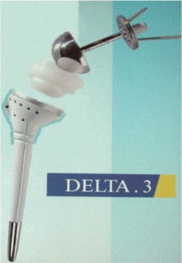
Initial Reverse Shoulder Prosthesis Design

Glenosphere sizes | Distance from glenoid to center of rotation of glenosphere (mm) | Micromotion (μm) |
32-mm neutral | 10 | 83.0 |
32 mm – 4 mm | 6 | 73.8 |
36-mm neutral | 6 | 73.9 |
36 mm – 4 mm | 2 | 64.8 |
40-mm neutral | 4 | 69.7 |
40 mm – 4 mm | 0 | 60.6 |
Fixation
Cementless fixation for prosthetic attachment to the bone has been utilized to allow for osseous integration, which provides for the secure long-term attachment between bone and prosthesis. However, the essential biomechanical prerequisite for this process to successfully occur requires a stable interface between the bone and the prosthetic device during initial healing while the tissue at the interface between the prosthetic surface and bone is undergoing maturation. A stable interface between a prosthesis and adjacent bone allows for successful bone ingrowth. Excess motion between the bone–prosthetic interface may result in failure of bone ingrowth and eventual mechanical failure of the device. The commonly accepted maximum motion that allows effective bony ingrowth is 150 μm.15
Typical joint loads that occur after shoulder arthroplasty and during early recovery include up to one times body weight (756 N). The ability to tolerate the application of such loads while successfully allowing bone to integrate into the prosthesis is dependent on how the applied load is transferred to the interface between the prosthesis and the bone, as well as the security of the attachment. Methods used to ensure proper attachment of prosthesis to bone include (1) improving the attachment strength to withstand the deforming loads transferred to the interface (improving fixation), and (2) limiting the deforming forces at the interface (immobilizing the shoulder, avoiding overtension of the reduction, or limiting the distance from the COR to the glenoid surface). Clinically, mechanical failures on the glenoid side have been seen in both currently available reverse shoulder designs (RSP and the Grammont design) and range from 0 to 60% of patients (Table 8–3).
To provide adequate fixation, principles developed by the Association for the Study of Internal Fixation (ASIF) to improve fracture healing were used in the development of the RSP. A key ASIF concept is that compression across a fracture promotes successful bone healing. When applied to prosthetic implants, compression between the prosthetic surface and the prepared bone provides stability needed to allow bone ingrowth. To achieve compression, the RSP design uses a 6.5-mm cancellous-type lag screw in the center of the baseplate (Fig. 8–7). The thread provides substantial compressive forces between the bone and the baseplate as the screw is driven into the bone. This differs from the Grammont design which uses a central post that does not provide compression. It must be noted that a small amount of compressive force is provided in the Grammont design from the peripheral screws. This leads to our first two studies described below, which compared a baseplate with central peg fixation to a baseplate with central screw fixation. The first study compared the compressive force present at the glenoid–baseplate interface and the second study compared the maximum load to failure.
Compressive Strength of Central Screw
Purpose
The purpose of this study was to determine the compressive force present at the glenoid–baseplate interface for central screw fixation and central peg fixation.
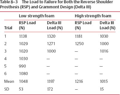
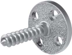
Figure 8–7 To achieve compression, the reverse shoulder prosthesis design uses a 6.5-mm cancellous type lag screw in the center of the baseplate.
Methods
The compressive strength of the central component of two different baseplates used to attach glenospheres to the scapula were compared: the metaglene (baseplate) of Grammont’s design and the RSP baseplate (Fig. 8–8). The Grammont design uses a central post, wheras the RSP design utilizes a 6.5-mm cancellous central screw. Surface preparation of each bone model was performed based on the manufacturer’s technique manual with matched reamers for the undersurface of each device. Force transducers were attached to the underside of each baseplate in superior and inferior positions prior to implantation. The base-plate of the Grammont design was impacted into the glenoid bone, while the RSP was screwed to 60 in lb of torque (as measured by a surgeon using a torque wrench during surgery). Both devices had all peripheral screws tightened to 60 in/lb of torque. Repeated measurements for the force at the interface between the baseplate undersurface and prepared bone were obtained.
Results
It was found that the screw fixation system of the RSP baseplate provided 2000 N of compressive force, whereas the peg/peripheral screw system of the Grammont design baseplate provided 200 N of compressive force (Fig. 8–9).
Maximum Load to Fixation Failure of Central Screw
Purpose
The purpose of this study was to determine the maximum load needed for failure of fixation for central screw fixation compared with central peg fixation.
Methods
Glenoid baseplate components for the RSP and the Grammont design were used. These baseplates were mounted into rigid polyurethane foam with properties similar to human glenoid cancellous bone. For the RSP baseplates, a 25-mm diameter concave surface was created using a hemispherical reamer and the baseplate was screwed into the foam until it was fully seated against the concave surface. For the Grammont baseplates, the central peg was tapped into the pilot hole until the baseplate was fully seated against the foam block. No additional peripheral screws were used for fixation of either baseplate.
A shear load was applied to the rim of each baseplate using a flat plane indenter attached to a servo-hydraulics load apparatus (model 8521, Instron Corp., Canton, MA) (Fig. 8–10). The load acted parallel to the baseplate surface and the displacement rate was 150 N/s. Load-displacement outputs were monitored continuously and tests were continued until a substantial drop in the load occurred with increasing displacement. This indicated that the yield strength of the foam substrate was exceeded and a failure of fixation between the foam and baseplate had occurred. The maximum shear load endured by each of the two baseplate-foam constructs was determined from the load-displacement curve. Three repetitions were completed for each baseplate.
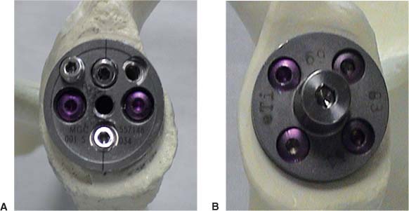
Figure 8–8 (A) The metaglene (baseplate) of Grammont’s design, and (B) the Reverse Shoulder Prosthesis baseplate.
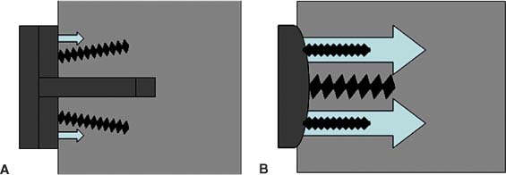
Figure 8–9 (A) Diagram of compressive forces present in the Grammont baseplate, and (B) the Reverse Shoulder Prosthesis baseplate.
Results
The maximum load at failure of fixation for the RSP base-plates with central screw fixation (631 N) was significantly (p = 0.012) greater than the Grammont design baseplates with central peg fixation (269 N). Baseplates with central screw fixation endured, on average, 2.3 times greater load than baseplates with central peg fixation.
Along with the central 6.5-mm cancellous screw, initial baseplate designs of the RSP employed four peripheral 3.5-mm diameter nonlocking, variable angle screws. These screws provided resistance to rotation of the baseplate, thus improving fixation and decreasing micromotion of the baseplate. Biomechanical testing was performed to understand further the fixation of the baseplates of the two available reverse shoulder designs using their appropriate peripheral screws.
Baseplate Micromotion Using 3.5-mm Peripheral Screws
Purpose
The hypothesis was that reverse shoulder baseplates with central screw fixation would have less motion during physiologic loading than baseplates with central peg fixation.
Methods
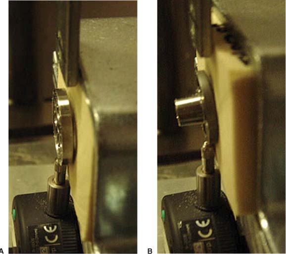
Figure 8–10 A shear load was applied to the rim of the (A) Grammont, and (B) Reverse Shoulder Prosthesis baseplates using a flat plane indenter attached to a servo-hydraulics load apparatus.
The RSP and Grammont baseplates were mounted in rigid polyurethane foam with properties similar to human glenoid cancellous bone. For the RSP baseplates, a 25-mm diameter concave surface was created using a hemispherical reamer and the baseplate was screwed into the foam until it was fully seated against the concave surface. For the Grammont baseplates, the central peg was tapped into the hole until the baseplate was fully seated against the foam block. Both baseplates were further secured with four peripheral screws, including two 3.5-mm diameter by 26-mm long cortical screws and two 4.5-mm diameter by 24-mm long cortical screws. The 3.5-mm screws were inserted at a 90-degree angle and the 4.5-mm diameter screws were inserted at a 60-degree angle relative to the baseplates. Two of the peripheral holes on the Grammont baseplate were threaded to mate with threads on the heads of the 4.5-mm screws. None of the peripheral holes on the RSP baseplate were threaded.
A shear load of 756 N was applied to the rim of each baseplate using a flat plate indenter attached to a servo-hydraulic load apparatus (model 8521, Instron Corp., Canton, MA). This load acted parallel to the baseplate surface with a displacement rate of 150 N/s. Baseplate motion was measured using a digital displacement gauge (model 543–683, Mitutoyo America Corp., Aurora, IL) with a resolution of 10 μm. Baseplate motion was defined as component displacement from 0 N to 756 N loads. Three repetitions were completed for each baseplate.
Results
Baseplate motion was significantly lower for the RSP base-plates at 310 ± 20 μm than the Grammont baseplates at 367 ± 23 μm (p = 0.016). Therefore, it was concluded that base-plate motion was significantly lower for reverse shoulder designs using a central cancellous screw and four peripheral cortical screws compared with reverse shoulder designs using a central peg and four peripheral cortical screws.
The attachment of the glenosphere to the baseplate (collectively called the glenoid component) increases the forces at the bone/baseplate junction. The choice of glenosphere also plays a part, as increasing the distance between the glenoid bone and the COR increases the forces seen at the bone/baseplate junction. As mentioned above, initial designs of the RSP were available with two glenosphere choices—the 32-mm neutral glenosphere with a COR (COR) 10-mm outside the glenoid and a 32 – 4 mm glenosphere with a COR 6-mm outside the glenoid. To determine the baseplate micromotion of the entire glenoid component (the glenosphere and the baseplate) with all peripheral screws under physiological loading and the maximum load at failure of fixation, two tests were conducted to determine loads to failure and micromotion during cyclic loading.
First, a servo-hydraulic machine was used to articulate the socket component with the glenosphere. A compressive and shear load was applied while load-displacement output was continuously monitored (Fig. 8–11). The tests were continued until a substantial drop in the shear load occurred with increasing displacement. The load to failure for both the RSP and the Grammont design was ~1000 N and not significantly different from each other (Table 8–3).
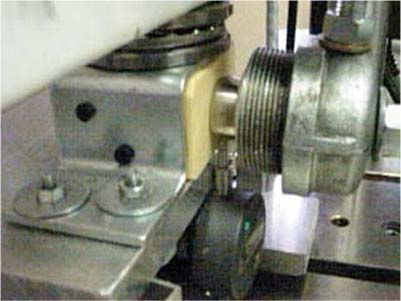
Figure 8–11 A servo-hydraulic machine articulating the socket component with the glenosphere.
Next, a study was conducted to evaluate the initial glenoid component fixation of the three different designs (RSP 32-mm neutral, 32 – 4 mm, and the Grammont 36 mm). Compressive and shear loads were applied to the glenoid components to create eccentric loading conditions similar to the rocking-horse loosening mechanism that has been observed in patients with rotator cuff deficiency treated with a total shoulder prosthesis.16 This study found that fixation of the two available RSP glenospheres with 3.5-mm screws demonstrated increased baseplate micromotion compared with the Grammont design. However, micromotion for all devices was below 150 μm, which is considered necessary for successful bone ingrowth.15 The results of this study provided some validation toward the use of RSP glenospheres with more lateral CORs that were fixed with 3.5-mm nonlocking screws.
Based on the above tests, it was apparent that the RSP, despite having a lateral COR, had adequate glenoid fixation. Unfortunately, clinical use of RSP 32-mm neutral and 32 – 4-mm glenospheres with 3.5-mm nonlocking screws resulted in mechanical failure of the baseplate in some of the devices. In total, 267 shoulders were implanted with the RSP between 1998 and 2004 exclusively using the 3.5-mm peripheral screws. Out of these 267 patients, there were 21 baseplate failures (7.8%). Evaluation of two of the initial baseplate failures was performed using scanning electron microscopy.
Scanning Electron Microscopy of Failed Baseplates17
Purpose
In an attempt to understand the failure mode of failed glenoid fixation, a retrieval analysis of failed baseplates was conducted.
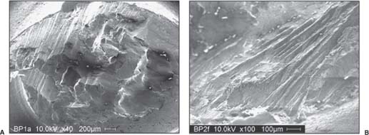
Figure 8–12 (A) Scanning electron microscope micrographs of the center screw, and (B) the baseplate undersurface.
Methods
A scanning electron microscope was used to determine if bone ingrowth occurred and to analyze fatigue characteristics at the center screw. Two baseplates were available for analysis.
Results
Minimal bone ingrowth was observed on the porous coating on the undersurface of the baseplate. The striations of the central screw could be accurately characterized as fatigue failure (Fig. 8–12).
Conclusion
The findings of these analyses suggest that baseplate failure was a fatigue phenomenon, which resulted in failure of bone ingrowth comparable to fixation failure occurring in nonunions.
Once it was determined that the mode of mechanical failure of the baseplate was fatigue fracture due to lack of bone ingrowth, attempts were made to further improve fixation of the baseplate. The idea of adding peripheral locking screws to provide additional baseplate fixation was conceived and the biomechanical study was repeated using 5-mm locking and nonlocking screws (Fig. 8–13).
Screw Fixation of Glenoid Components Using 5.0-mm Screws18
Purpose
This study was divided into two experiments. The first experiment measured the baseplate micromotion after varying the screw diameter, screw type, and/or glenosphere type. The second experiment used an “offset gauge” device to compare baseplate motion within a range of lateral offset magnitudes, using two types of peripheral screws for fixation. Lateral offset was defined as the distance from the glenoid baseplate to the center of articular contact between the glenosphere and the polyethylene cup.
Methods: First Variation
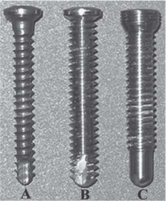
Figure 8–13 (A) 3.5-mm-diameter nonlocking, (B) 5.0-mm-diameter nonlocking, or (C) 5.0-mm-diameter locking screws.
Two variations of the RSP glenosphere (32-mm neutral and 32 – 4 mm) were tested in addition to a 36-mm glenoid component of the Grammont design. These devices had varying lateral offsets, defined as the distance from the glenoid baseplate to the center of articular contact between the glenosphere and the polyethylene cup. Baseplate micromotion was used as an indirect measure of the adequacy of fixation. The baseplate of the 36-mm Grammont design glenosphere (COR at the glenoid) was implanted with two captured 3.5-mm locking screws implanted at 90 degrees relative to the baseplate and 2 nonlocking screws implanted at 60 degrees, following standard operating procedure. The baseplates of the RSP 32-mm neutral and 32 – 4-mm glenospheres (COR 10 and 6-mm outside the glenoid surface, respectively) were implanted with either four 3.5-mm nonlocking screws, four 5.0-mm nonlocking screws, or four 5.0-mm locking screws. Two 3.5-mm nonlocking screws were implanted into RSP baseplates at 60 degrees and two 3.5-mm nonlocking screws were implanted at 90 degrees. All 5.0-mm screws were implanted at 90 degrees with respect to the baseplate. All three glenosphere/baseplate combinations were implanted into high-strength polyurethane foam (Sawbones Solid Rigid Foam 1522–04, Pacific Research Laboratories, Vashon, WA) with properties similar to excellent glenoid bone stock.
Compressive loads and shear loads of 756 N (one times bodyweight) were applied to the glenoid components to create eccentric loading conditions similar to the rocking-horse loosening mechanism that has been observed in patients with rotator cuff deficiency treated with a total shoulder prosthesis.16 The polyethylene humeral components were attached to the load apparatus and loads were applied at a loading rate of 150 N/s and cycled in the superior and inferior direction between +756 N and -756 N for 1,000 cycles. Motion was defined as the difference in glenoid component displacement at 0 N and 756 N loads measured after 1,000 cycles. At least 3 repetitions of each test were completed. The calculated moment at the baseplate-foam interface was 12.1, 17.4, and 20.4 Nm for the Grammont design, RSP 32 – 4-mm, and RSP 32-mm neutral components, respectively.
Results: First Variation
The first experiment revealed that Grammont components fixed with 3.5-mm screws had significantly less motion than the RSP 32 – 4-mm (p = 0.017) and RSP 32-mm neutral (p = 0.041) components fixed with 3.5-mm screws and RSP 32 – 4-mm (p = 0.008) and 32-mm neutral (p = 0.006) components fixed with 5.0-mm nonlocking screws. However, there were no significant differences (p = 0.151) in component motion when the Grammont components fixed with 3.5-mm screws were compared with the RSP 32-mm neutral and RSP 32 – 4-mm components fixed with 5.0-mm locking screws (Fig. 8–12). Baseplate motion for Grammont components and RSP components fixed with 5.0-mm locking screws was below the 150 μm of motion generally accepted as the threshold for bone ingrowth.15 Among the RSP components, baseplates fixed with the 5.0-mm locking screws had less mean motion than did base-plates fixed with the 5.0-mm nonlocking screws (p = 0.016) or the 3.5-mm nonlocking screws (p = 0.067) (Fig. 8–14).
Methods: Second Variation
Related posts:
 Tissue Engineering for the Rotator Cuff–Deficient Shoulder
 The Spectrum of Disease in the Rotator Cuff–Deficient Shoulder
 Muscle Transfers for the Treatment of the Irreparable Rotator Cuff Tear
 Hemiarthroplasty for Rotator Cuff–Tear Arthropathy
 Rationale and Biomechanics of the Reversed Shoulder Prosthesis: The French Experience
 Arthroscopic Management of Massive Rotator Cuff Tears
Stay updated, free articles. Join our Telegram channel

Full access? Get Clinical Tree


