Chapter 16 Radiologic Aspects of Orthopedic Diseases
This chapter contains a radiologist’s viewpoints and suggestions regarding the interpretation of bone roentgenograms. It is hoped this will serve as a useful and practical guide for the busy physician. Principles concerning roentgenographic positioning, anatomy, and pathology are presented by using a regional anatomic approach. Additionally, the musculoskeletal applications of specialized radiologic modalities are discussed. This includes comments on nuclear medicine procedures, diagnostic ultrasound, arthrography, and angiography. Importantly, the imaging technologies of computed tomography (CT) and magnetic resonance imaging (MRI) as they pertain to the evaluation of orthopedic problems are detailed.
General Considerations of Roentgenographic Bone Anatomy
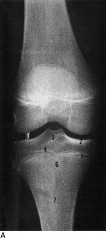
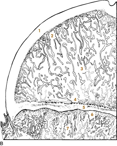
Before beginning a detailed discussion of regional roentgenographic anatomy and pathology, a consideration of pertinent radiologic bone anatomy is important. A bone can be evaluated according to its various components (Fig. 16-1).
APOPHYSIS
There are several apophyses throughout the skeletal system; the best example is the greater trochanter of the proximal portion of the femur. Apophyses do not contribute to bone growth but are considered accessory ossification centers. They tend to appear later than the epiphyses in normal bone development and form protrusions to which ligaments and tendons attach.
BONE VESSELS
There is only indirect evidence of the presence of blood vessels on roentgenograms, and it is the nutrient canals and foramina. They enter the medullary cavity by way of foramina, most often near the midshaft of a long bone, and result in radiolucent channels. When viewed on the roentgenogram, these channels can be confused with a fracture. Prominent nutrient canals frequently are seen in the diaphyses of the femur and tibia. Y-shaped nutrient canals occur in the midportion of the iliac bones of the pelvis and in the subspinous region of the scapulae.
Analytic Approach to Bone Changes
SPECIFIC PARAMETERS
Certain specific parameters of bone need careful attention. In the process of evaluating these, using a systematic approach can lead to a logical conclusion. Among the criteria to be analyzed are an increase or decrease in bone density, alterations in osseous texture (trabecular pattern), periosteal reactions, and the conditions of the cortex, endosteum, and medullary spongiosa. If any changes of these are observed, then the abnormality should be studied in terms of its size and configuration and the sharpness of its margins (transition zone). The specific bone involved and the position of the lesion within that bone (epiphysis, metaphysis, or diaphysis) should also be noted. For example, leukemia, metastatic neuroblastoma, a benign simple cyst, and Brodie’s abscess have a predilection for the metaphysis, whereas a chondroblastoma typically involves the epiphysis.
This is a simple, general outline, and many more particulars come into play. By developing this type of approach, the many clues offered will help to determine the nature of the pathologic process and place the lesion into a certain category (for example, benign, malignant, infectious, traumatic, or metabolic). Table 16-1 lists some of the specific characteristics of different bone lesions.
Table 16-1 General Characteristics of Different Bone Lesions
| Characteristics of benign bone lesions |
| Sclerotic margins (narrow transition zone) |
| Homogeneous periosteal reaction |
| Expansion of an intact cortex |
| Characteristics of solitary malignant bone lesions |
| Permeative or moth-eaten destruction (wide transition zone) |
| Irregular, sometimes spiculated periosteal reaction |
| Preferential metaphyseal location |
| Extraosseous extension with soft tissue mass and occasional fluffy calcifications |
| Characteristics of metastatic lesions |
| Absence of periosteal reaction |
| Moth-eaten destruction of medulla and cortex |
| Preferential diaphyseal location |
| Pathologic fractures |
| Multiple bone involvement |
| Characteristics of infection |
| Often irregular periosteal reaction, no spiculation |
| Bone destruction variable |
| Diaphyseal involvement, often involving long segments |
| Destruction of adjacent cartilage, crossing joints (majority of malignant neoplasms lack this ability) |
| Sequestration and involucrum formation |
PATTERNS OF BONE DESTRUCTION
TYPES OF PERIOSTEAL REACTIONS
When the outer periosteal membrane of bone is irritated, its constituent osteoblastic cells react by producing new bone. This new bone can take on either a solid or an interrupted appearance, and the specific form can assist in identifying the inciting cause (Table 16-2). Solid periosteal reactions are usually indicative of a benign process. The new bone is consistently uniform in density. As seen in Table 16-2, the thickness and marginal characteristics vary according to the precipitating factor.
Table 16-2 Roentgenographic Types of Periosteal Reactions*
| Types | Examples |
|---|---|
| Solid periosteal reaction | |
| Thin | Eosinophilic granuloma, osteoid osteoma |
| Thin undulating | Hypertrophic pulmonary osteoarthropathy |
| Dense undulating | Vascular |
| Dense elliptical (with destruction) osteoid osteoma | |
| Cloaking | Long-standing malignancy |
| Chronic infection | |
| Interrupted periosteal reaction | |
| Perpendicular (spiculated or sunburst) | Osteosarcoma, Ewing’s sarcoma, infection |
| Lamellated (onion skin) Osteosarcoma, | Ewing’s sarcoma, infection |
| Amorphous | Malignant tumors |
| Codman’s triangle | Malignant tumors, infection, hemorrhage |
* From Edeiken J, Hodes PJH: Roentgen diagnosis of diseases of bone, Baltimore, 1967, Williams & Wilkins. Used by permission.
The interrupted forms of periosteal reactions are more commonly found in malignant disease, although benign lesions such as infection are occasionally responsible. The classic spiculated or sunburst pattern of osteogenic sarcoma and the lamellated or onion skin, periosteal reaction of Ewing’s sarcoma come under this heading (see Table 16-2).
Regional Anatomic and Pathologic Roentgenography
CERVICAL SPINE
ROENTGENOGRAPHIC EXAMINATION
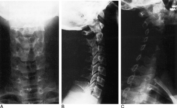
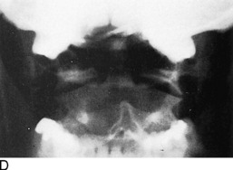
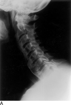
The standard roentgenographic views of the cervical spine include anteroposterior, lateral, and both posterior oblique views, as well as an open-mouth anteroposterior projection of the odontoid process and the first two cervical vertebral segments (Fig. 16-2). The majority of cervical spine studies are performed for the evaluation of trauma. In the more severely injured individual, the most important views are a cross-table horizontal beam lateral image and an anteroposterior supine film. By keeping patient movement to a minimum, potentially fatal spinal cord injury is prevented.
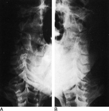
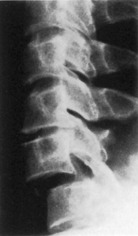
Dr. Don Weir of Saint Louis University developed the “pillar view” for better evaluation of the lateral articulating masses, the superior and inferior articulating facets, and their intervening joints. Moreover, this view brings into focus the anterior and posterior margins of the lamina (Fig. 16-3). The film is produced with the patient supine. Each side is done separately. The head is turned very slightly to one side, with the roentgenograph tube angled toward the feet 35 to 45 degrees and centered over the middle to lower vertebrae. The opposite side is then examined in a similar manner.
ROENTGENOGRAPHIC ANATOMY
A thorough understanding of the roentgenographic anatomy of the cervical spine is an absolute prerequisite to its proper evaluation. Each component of the individual vertebrae should be appraised separately on all views.
Odontoid View
Of the seven cervical vertebrae, the first two are anatomically distinct. The odontoid represents a superior extension of the body of C2 and is actually the vestigial body of C1. On the anteroposterior open-mouth film, the odontoid should be analyzed in terms of its position between the two lateral articulating masses of C1 (see Fig. 16-2, D). The spaces between the lateral edges of the odontoid and the medial borders of the C1 articulating masses should be equal. However, minor degrees of rotation can produce spurious inequality of these interval distances. How can this be determined? The alignment of the densities of the spinous processes of C1 and C2 can be seen. If the C2 spinous process is to one side or the other, then rotation is present.
Also on viewing the odontoid film, the transverse processes and lateral borders of the articulating masses of C1 and C2 should not be overlooked. The horizontal joints between the atlantoaxial articulating masses should be symmetric (see Fig. 16-2, D).
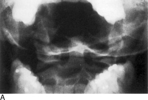
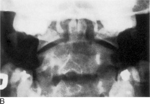
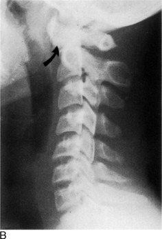
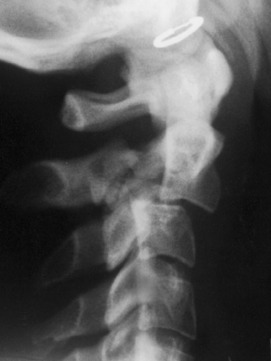
Confusing artifacts superimposed on the odontoid can be misleading and can result in misinterpretation of fractures of this structure. The inferior margin of the anterior or posterior arch of C1 can overlie the base of the odontoid and create a “Mach” effect, a radiolucent line produced by overlap of the edges of two bones. In a similar fashion, the space between the two incisor teeth may lay over the odontoid and yield an artifactual vertical cleft (Fig. 16-4).
It is not unusual for the odontoid process to be completely obscured by the base of the occipital bone if the head is held too far in extension. In such circumstances, have the view repeated with the patient’s head slightly more flexed.
Lateral View
Several important points must be remembered when viewing the lateral projection of the cervical spine (see Fig. 16-2, B). Alignments of the anterior and posterior borders of the vertebral bodies, alignment of the lateral articulating masses, and alignment of the spinolaminar line are studied. The latter is formed by the anterior margins of the spinous processes, which also describe the posterior surface of the spinal canal. The superior extension of this line is in direct alignment with the posterior margin of the foramen magnum.
The superior and inferior articulating facets ordinarily are well visualized on the lateral film. The posterior borders of the lateral articulating masses should form a straight line (see Fig. 16-2, B). If there is a slight offset, a facetal dislocation must be considered, although slight rotation can give a similar appearance. The view should be repeated if there is any confusion, and if the problem persists, CT scanning should be considered.
Oblique Views
The intervertebral foramina and surrounding elements, including the pedicles and uncinate processes, are the most important components demonstrated on the oblique views. The foramina on the right side are visualized on the left posterior oblique projection and those on the left on the right posterior oblique film (see Fig. 16-2, C).
TRAUMA
Recognition of an abnormal cervical spine should be a relatively simple task once normal roentgenographic anatomy has been mastered. After a traumatic lesion has been identified, the primary objective is the establishment of whether the condition is stable. The stability of a fracture is best determined by grouping the type of injury according to the mechanisms of trauma, which are outlined in Table 16-3. From this classification, a statement of the instability of the injury can be made (Table 16-4).
Table 16-3 Classification of Cervical Spine Injuries According to the Mechanisms of Injury*
| Flexion |
| Subluxation |
| Bilateral interfacetal dislocation |
| Simple wedge fracture |
| Flexion teardrop fractures |
| Clay-shoveler’s fracture |
| Flexion-rotation |
| Unilateral interfacetal dislocation |
| Vertical compression |
| Bursting fractures |
| Jefferson’s C1 |
| Bursting fractures, other levels |
| Extension |
| Posterior neural arch fracture |
| Extension teardrop fracture |
| Hangman’s fracture |
* From Harris JH Jr: Acute injuries of the spine, Semin Roentgenol 13:53–68, 1978. Used by permission.
Table 16-4 Classification of Cervical Spine Injuries Based on Stability*
| Stable |
| Subluxation |
| Simple wedge fracture |
| Unilateral interfacetal dislocation |
| Bursting fracture, except Jefferson’s fracture of C1 |
| Clay-shoveler’s fracture |
| Unstable |
| Bilateral interfacetal dislocation |
| Flexion teardrop fracture |
| Jefferson’s bursting fracture of C1 |
| Hangman’s fracture |
| Extension teardrop fracture, unstable in extension but stable in flexion |
* From Harris JH Jr: Acute injuries of the spine, Semin Roentgenol 13:53–68, 1978. Used by permission.
Flexion Injuries
There are a variety of flexion injuries, which are described below.
Subluxation
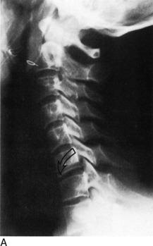
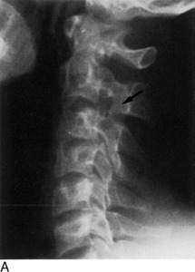
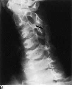
The roentgenographic findings in this stable lesion may be minimal, often requiring flexion and extension lateral views for confirmation. The body and posterior elements remain intact; that is, show no fracture. However, there is major soft tissue involvement. The interspinous and posterior longitudinal ligaments, as well as the interfacetal joint capsules, are disrupted at the affected level. This allows the involved vertebral body to rotate anteriorly about its anterior and inferior corner, along with upward and forward displacement of its inferior articular facet on the lower adjacent vertebra’s superior articular facet. The interspinous distance widens, and the inferior intervertebral disc space narrows anteriorly and widens posteriorly. These alterations are accentuated on the flexion film (Fig. 16-5). In children younger than 8 years, with the head held in flexion, the second cervical vertebra is normally displaced anteriorly over C3. This malalignment must not be mistaken for subluxation.
Clay-Shoveler’s Fracture
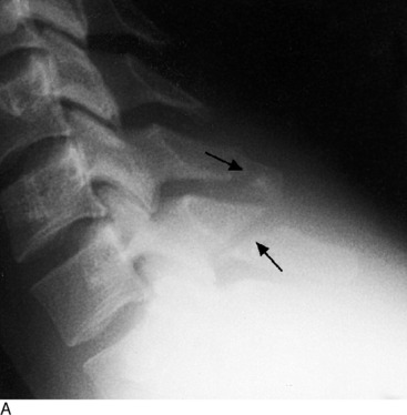
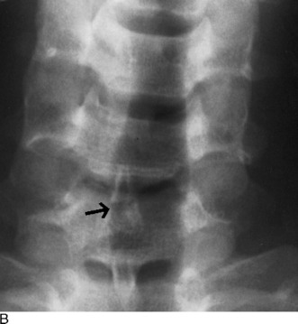
This lesion is named for the injury acquired by people in occupations that require heavy lifting. This injury consists of a fracture through the spinous process of either C6 or C7 (Fig. 16-6). There is no significant ligamentous damage, and therefore a stable condition exists. Because C7 is sometimes difficult to project on the lateral film, the fracture can be missed. A clue might be apparent on the frontal film, where an extraspinous process fragment is sometimes evident as the result of inferior displacement. An unfused apophysis of a spinous process must not be misinterpreted as a fracture (Fig. 16-7).
Flexion-Rotation Injuries
When the cervical spine is subjected to a rotational force in addition to flexion, a unilateral interfacetal dislocation may be observed (Fig. 16-8). An inferior articular facet of one body is displaced over the adjacent superior articular facet of the next inferior vertebra on one side only. The dislocated facet is more or less locked in place, but because of associated ligament damage, the lesion may be unstable; therefore, flexion and extension views are contraindicated. Oblique projections are most productive in identifying the displaced facet, but it may be suggested on the lateral film when the margins of the facets of a single vertebra do not superimpose on one another as the result of rotation. Additionally, a line drawn through the posterior borders of the bodies is offset at the level of the suspected injury.
Extension Injuries
Various extension injuries are described as follows.
Posterior Neural Arch Fractures
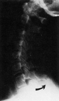
The neural arch of one vertebra may be compressed between the posterior elements of the two adjoining vertebrae during maximal forced extension. A unilateral or bilateral fracture may be sustained. If bilateral, the fragment can be displaced posteriorly, yet there will be no encroachment on the neural canal; thus, the situation is a stable one (Fig. 16-9).
Extension Teardrop Fracture
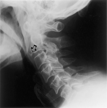
Similar to the flexion variety, an extension teardrop fracture demonstrates a triangular-shaped fragment at the anterior-inferior margin of the body, most often involving C2, although other levels are affected (Fig. 16-10). However, the injury is not quite as severe, because there is no posterior involvement. When the neck is held in flexion, there is stability of the spine because the posterior ligament complex is intact. However, instability occurs during extension because the minor fragment remains attached to the anterior longitudinal ligament but not to the parent body.
Hangman’s Fracture-Dislocation of C2
This lesion consists of vertical disruption of both pedicles of C2 and is created by flexion forces against the extended vertebrae. The body of C2 is thrust forward over C3, with concomitant rupture of both the anterior and the posterior longitudinal ligaments, giving rise to an unstable injury (Fig. 16-11).
Vertical Compression Fractures
A considerable force directed through the vertical axis of the spine (such as a large object falling on top of the head or a diving injury) can produce the so-called bursting fractures of the cervical vertebrae. The least common type is the Jefferson fracture of C1. The anterior and posterior aspects of the ring are fractured on both sides, with bilateral lateral displacement of the fragments. This unstable injury can be apparent on the open-mouth anteroposterior film but more reliably is distinguished on the lateral roentgenogram where the fractures are seen to extend through the posterior arches.
THORACIC AND LUMBAR SPINE
Roentgenographic Anatomy
Anteroposterior View
On the anteroposterior projection, the spinous processes provide another guide for the evaluation of alignment. Rarely, they may be absent because of aplasia or malignant or infectious destruction.
Oblique Views
Important anatomic features are introduced on the oblique views of the lumbar spine. These details have been covered more extensively in Chapter 8. On the left posterior oblique film (left side down against the film), the left half of the posterior neural arch elements, including the intervertebral foramina, are identified, whereas the right half of these components are viewed on the opposite projection. In the cervical spine, the reverse condition exists.
DEVELOPMENTAL VARIATIONS AND CONGENITAL ABNORMALITIES
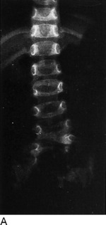
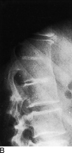
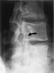
Confusing anatomic variations are seen in the developing and mature spine. In infancy, the vertebral bodies are egg-shaped on lateral view. The upper and lower anterior corners are beveled until the apophyseal vertebral rings appear about each end plate. They fuse with the body by the fifteenth year, but occasionally they remain ununited and, except for the presence of a complete sclerotic border, often are confused with a corner fracture (Fig. 16-12). These are sometimes referred to as limbus vertebrae.
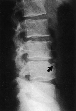
Fig. 16-12 An unfused ring apophysis of a lumbar vertebra as seen here can be confused with a fracture.
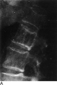
On the anteroposterior film, a vertical radiolucent cleft is seen superimposing on the vertebral bodies (Fig. 16-13). This represents the normal uncalcified portion of the posterior neural arch and spinous process and is not to be confused with spina bifida. At approximately 3 to 5 years of age, these will ossify and fuse. When they do fail to fuse completely, the cleft persists as a spina bifida occulta. This can occur anywhere in the spine, but is most common at L5. These are of no clinical importance.
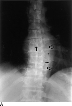
Hypoplasia of the vertebrae, fusion or block vertebrae, and hemivertebrae constitute a few of the other possible spinal anomalies (Fig. 16-14).
TRAUMA
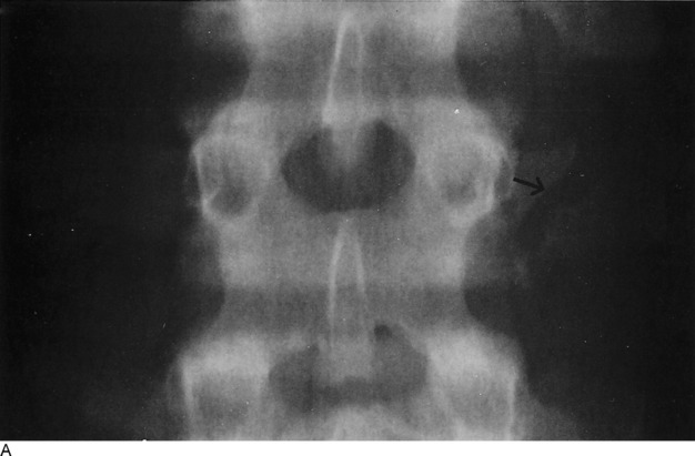
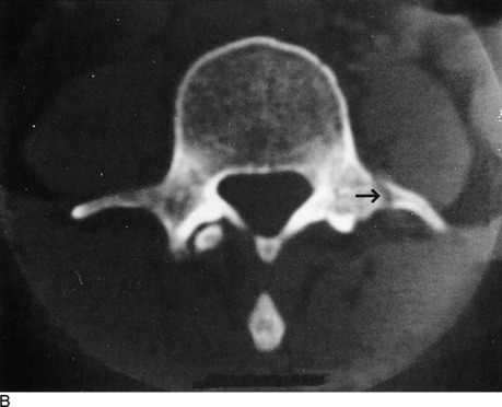
Another important traumatic lesion, particularly of the lumbar spine, that can be easily overlooked is the transverse process fracture (Fig. 16-15). The importance of its recognition rests with the fact of frequently related renal injury. It is important not to mistakenly call the unfused apophysis of the transverse process a fracture.
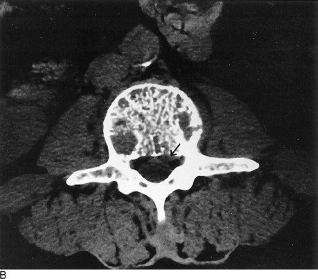
A seldom-seen injury to the lumbar vertebrae is the Chance fracture (Fig. 16-16). An extreme flexion force, often related to seat belt injuries, causes a fracture through the spinous process, across the neural arch or lamina, and into the posterosuperior aspect of the vertebral body. An isolated fracture of the spinous process is uncommon in the thoracic and lumbar regions.
One more pitfall to watch for in the assessment of spinal trauma is the unfused ossification center of the articular facets, which can resemble a fracture (Fig. 16-17). In evaluating the posterior elements, it is important to keep in mind the entities of spondylolysis and spondylolisthesis (see Chapter 8).
TUMORS
Hemangioma
Hemangiomas of the vertebral body may be the most common benign tumor, although few have been documented pathologically. Typically, their appearance is that of increased vertical trabeculations producing a somewhat striated pattern (Fig. 16-18). They should not be confused with Paget’s disease or osteoblastic metastasis.
Aneurysmal Bone Cyst
Of the benign tumors of the spine, aneurysmal bone cysts are possibly the next most frequent after hemangiomas. They are more commonly found in the extremities, especially the distal portion of the femur. In the spine, they tend to involve the posterior elements as well as the body. Possessing a thin shell of peripheral bone, they are expansile and cystic in nature. Roentgenographically, a malignant appearance can be seen with a predominant cystic pattern. Unlike other tumors, benign and malignant alike, aneurysmal bone cysts have the unique capability of crossing over the cartilaginous disc space to involve adjacent vertebrae. A malignant chordoma also has this potential.
Hodgkin’s Lymphoma
Hodgkin’s disease can occasionally be seen within the bony spine and may present as an osteolytic or osteoblastic alteration or a combination of the two. However, more commonly, paraaortic lymph node involvement with lymphoma produces erosive changes of the vertebral cortical margins.
INFECTION
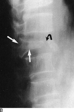
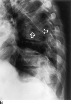
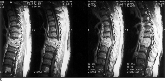
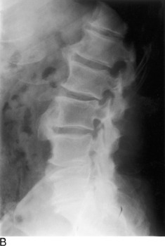
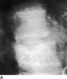
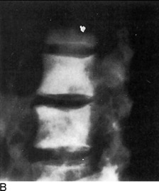
In both pyogenic discitis and vertebral osteomyelitis, the earliest roentgenographic findings may be joint space narrowing. Depending on the aggressiveness of the offending bacteria and the time of institution of therapy, the surrounding bone shows varying degrees of demineralization brought on by hyperemia. The end plates then demonstrate progressive loss of continuity with irregular destruction and focal areas of subchondral reactive sclerosis. Extension into the posterior third of the body, then into the dorsal appendages, as well as into the adjoining vertebrae, may occur. The body may eventually collapse. Some degree of surrounding soft tissue swelling is invariably present and detectable on roentgenograms and corroborated on MRI (Fig. 16-19).
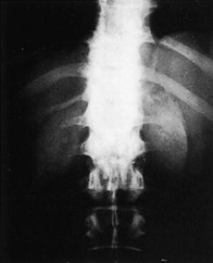
Because of its insidious and chronic nature, the spinal lesions are usually advanced when first examined roentgenographically, although this is not always the situation. An occasionally prominent feature is a large paravertebral soft tissue mass that constitutes the abscess. In later phases, there may be extensive calcification within this mass (Fig. 16-20). The bony structures show a decrease in density, and there is narrowing of one or more of the disc spaces. The margins of the end plates manifest irregular destruction, and a mottled sclerotic and lytic appearance extends into the bodies, which display varying degrees of compression.
SPINAL ARTHRITIS
Arthroplasty of spondylosis of the spinal column most commonly is degenerative in nature with the formation of hypertrophic bony spurs. These osteophytes are formed by recurrent stimulation of wear and tear factors, and are predominantly located along the end-plate margins of the vertebral bodies. When they bridge the interspaces and fuse, such spurs are described as syndesmophytes, which can more often be identified in specific forms of arthritis, such as diffuse idiopathic skeletal hyperostosis (DISH; Fig. 16-21).
Ossification of the anterior longitudinal ligament of the spine is characteristic of ankylosing spondylitis (Marie–Strümpell disease). Psoriatic arthritis, Reiter disease, and other autoimmune diseases (including inflammatory bowel diseases) may lead to exuberant osteophyte formation.
PAGET’S DISEASE
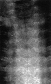
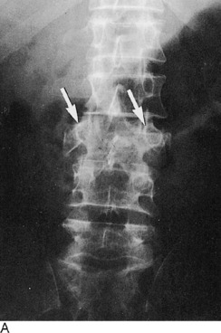
One of the distinctive roentgenographic characteristics of spinal Paget’s disease is that the disorder involves the entire vertebra—the body and all of the posterior elements, including the transverse and spinous processes (Fig. 16-22). Generally, there is an increase in density produced by a thickened trabeculae. A picture frame appearance can be imparted to the body, the result of a dense peripheral margin of thickened cortex. Furthermore, there is an actual increase in volume of the entire vertebra. This finding, along with total vertebral involvement, distinguishes Paget’s disease from an osteoblastic metastasis.
THE SHOULDER
ROENTGENOGRAPHIC EXAMINATION
In the majority of cases, a complete and optimal roentgenographic study of the shoulder girdle needs only include upright—standing or sitting—anteroposterior views with the humerus in internal and external rotation. These two projections usually permit adequate evaluation of the bony structures constituting the shoulder. In the uncooperative child or severely traumatized patient, these films may be obtained while the patient is in the supine position. On these roentgenograms, the complete clavicle should be visualized in addition to the entirety of the scapula and at least the proximal third of the humerus. Special attention should be given to the alignments of the glenohumeral, acromioclavicular, coracoclavicular, and sternoclavicular joints. The tuberosities of the humeral head and its articular surface should be specifically scrutinized. The acromium and coracoid processes, in addition to the borders and flat surfaces of the scapula, require attention.
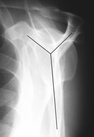
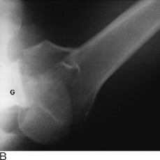
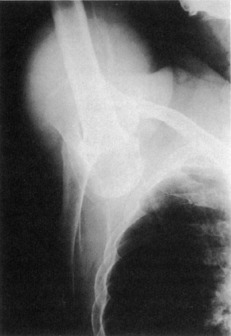
When there is suspicion of a fracture involving the shaft of the humerus below the neck, in addition to an anteroposterior view, a transthoracic lateral projection is necessary for evaluation of alignment (Fig. 16-23). The glenohumeral relationship can also be accessed with proper exposure, but because of superimposed ribs, fractures above the neck are difficult to see. Instead, a transscapular study is more helpful (Fig. 16-24). This view is obtained by having the patient face the film at an angle of 45 degrees with the affected side toward the film holder. The resultant picture forms a Y where the acromium, coracoid, and scapular body intersect. The humeral head will be superimposed on the Y. This is useful not only for fractures but also for posterior dislocations. This transscapular examination is always used when studying the scapula, in addition to the routine anteroposterior roentgenogram. CT or MRI imaging, particularly the latter, can provide additional valuable information especially regarding soft tissue involvement. The multiplanar capabilities of these imaging modalities augments visualization of gross pathologic findings.
Posterior shoulder dislocations are notorious for their ability to avoid detection on the standard anteroposterior views; they are frequently associated with seizure disorders. The tangential projection is an excellent means for detecting the abnormality. This is performed by angling the roentgen tube approximately 30 degrees so that the central ray passes tangentially across the glenoid articular surface. In this manner, the glenohumeral relationship is much better defined than on the conventional straight anteroposterior view.
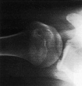
The axillary film also provides another perspective of the shoulder anatomy (Fig. 16-25). The acromium, coracoid, glenohumeral joint, and humeral head are viewed in a different plane. By holding the film against the top of the shoulder, the picture is produced by abducting the arm and centering the roentgen tube through the axilla. The study requires a special “grid” cassette for the film. It is helpful in determining the presence of a humeral head displacement, but it is not recommended when a dislocation has just been reduced, because the required abduction may reluxate the joint.
A more difficult area to examine roentgenographically is the sternoclavicular joint. Because of bony superimposition, CT may be required, but because this is not universally available, both oblique and lateral views may suffice. However, if these attempts are unsuccessful, the patient can be positioned prone. The roentgen tube is then centered through the sternoclavicular joints and angled toward the head at a 35-degree tilt.
ROENTGENOGRAPHIC ANATOMY AND DEVELOPMENTAL VARIATIONS
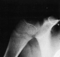
A considerable degree of confusion can be created by the ossification centers of the shoulder. The proximal humeral epiphysis does not become visible, as a rule, until the fourth to eighth month of life. There are two, occasionally three, separate centers. By the age of 20, the proximal epiphysis fuses to the shaft of the humerus. Before complete closure of the epiphyseal suture, the lucent line has a peculiar angulated appearance (Fig. 16-26). Overlap of the suture line occurs no matter what projection is used and consequently produces an image simulating a fracture.
TRAUMA
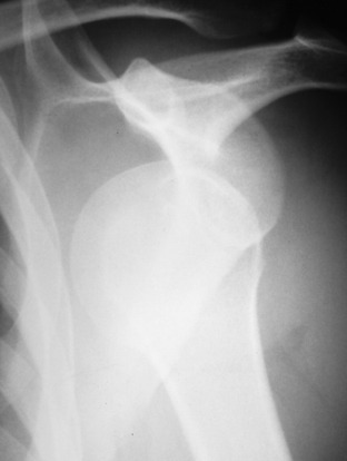
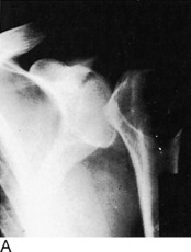
Of all the joints in the body, the shoulder is the most frequent site of dislocations. More than 97% are anterior and can be described as subglenoid or subcoracoid, depending on the location of the humeral head. Invariably, this form of dislocation can be visualized by a single anteroposterior roentgenogram (Fig. 16-27). Whenever a dislocation occurs, it is not unusual to have an associated fracture; this should be searched for on the film. With an anterior dislocation, a fracture of the greater tuberosity may exist; the lesser tuberosity is vulnerable in posterior dislocations. The lower glenoid margin is also susceptible in either type of dislocation. An infraction of the articular cartilage without a visible fracture is also possible in dislocations and may require MRI to demonstrate.
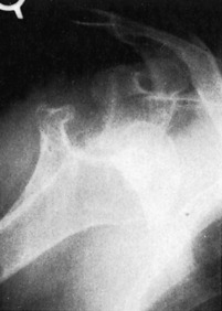
With chronic recurring anterior dislocations, a defect becomes apparent along the superolateral aspect of the humeral head. This cortical infraction, present because of impaction against the anteroinferior rim of the glenoid, is commonly referred to as Hill–Sachs deformity. This abnormality is usually best demonstrated on an internally rotated anteroposterior view (Fig. 16-28).
The less frequent posterior dislocation is much more difficult to visualize roentgenographically. The problem arises because the humeral head on the standard anteroposterior projections shows no apparent separation from the glenoid fossa when in fact it is separated. The posterolateral orientation of the glenoid articular surface accounts for this to some extent. Ordinarily, in the normal shoulder the head of the humerus overlaps about three fourths of the glenoid fossa. When it becomes posteriorly dislocated because of lateral displacement of the head, this overlap is less, but the change may be very subtle. This perplexing situation can usually be solved by using the 30-degree tangential view, the axillary projection, or the transscapular film (Fig. 16-29). With recurrent posterior dislocations of the shoulder, a defect of the inferoposterior cartilagenous labrum may not be visible by stand-ard radiography. This is termed a Bankart lesion, which can be diagnosed by MRI or CT arthography.
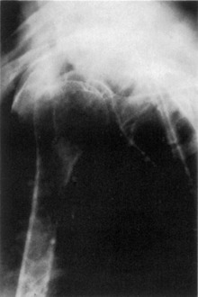
A very rare form of dislocation of the shoulder joint is luxatio erecta, a condition where the humeral head is located under the glenoid rim and the humeral shaft is directed above the head in fixed abduction (Fig. 16-30). A lateral fall on an elevated arm produces such an abnormality. The acromium process of the scapula acts as a fulcrum pushing the head of the humerus down and out of the glenohumeral joint. The dynamics of the applied forces can result in a fracture of the acromium, the lower lip of the glenoid, or the greater tuberosity of the humerus. Often, there is an associated tear of the rotator cuff.
Transverse subcapital fractures of the surgical neck along with avulsions of the greater tuberosity are the most commonly encountered injuries to the shoulder. A fracture-displacement of the ununited epiphysis creates a more difficult diagnostic challenge. The normal epiphyseal line itself, as already mentioned, makes interpretation troublesome. The normal epiphysis has a uniform width and dense margins, whereas a fracture demonstrates varying thickness with a sharp, nonsclerotic edge. Often, there is impaction or distraction of the fragments causing some degree of overlapping, which makes the diagnosis somewhat simpler. Of course, if the presence of an abnormality is uncertain or indeterminate, an accurate comparison with the opposite uninjured shoulder should be performed.
TUMOR
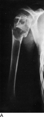
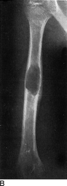
The proximal aspect of the humerus is a relatively common location for a benign solitary cyst, which may appear as either simple or multiloculated (Fig. 16-31). Such cysts are found within the metaphysis and exhibit destruction of the medullary spongiosa with more or less expansion of the bone. Thinning of the cortex can attain paper thickness, and pathologic fractures are a very common event, even in the absence of significant trauma. When initially discovered, the cysts extend to the epiphyseal line but do not involve the growth center itself. When followed serially until fusion of the epiphysis, the cyst appears to “migrate” toward the middle of the shaft as growth of the bone ends progresses.
Stay updated, free articles. Join our Telegram channel

Full access? Get Clinical Tree


