Radiographic Evaluation of the Hip
Michael Cooley
Debora Azevedo
William Palmer
Introduction
We review several imaging modalities used routinely in clinical practice to evaluate the hip. The primary focus involves modalities that depend on ionizing radiation for image production, such as radiography, fluoroscopy, and computed tomography (CT). We address image acquisition techniques, radiation risks, and diagnostic capabilities. Radiographic modalities may be sufficient for evaluation, or may require supplementation by other imaging modalities including magnetic resonance imaging (MRI). MRI has an established role in the assessment of bone marrow disorders, myotendinous lesions, and internal derangements of the hip. Although the technical factors related to MRI are presented in a subsequent chapter, we incorporate MR images into many of our figures for correlation with other modalities. In the illustration of clinical scenarios, we compare the relative strengths of these modalities and distinguish their diagnostic advantages in the evaluation of patients with hip symptoms.
Technical Considerations
Radiographic Image Acquisition and Technique
Radiographic protocols designed for the hip can vary based on the clinical scenario and personal preference of the referring physician. The majority of examinations include an anteroposterior (AP) view of the hip and a lateral view that could be either a true lateral or frog-leg lateral (1). These views and other specialized views are discussed below (Fig. 23.1). An AP view of the entire pelvis is included in many routine examinations.
In the absence of known trauma or suspected proximal femoral fracture, the ipsilateral hip is internally rotated approximately 15 degrees to obtain the AP view (Fig. 23.2). Internal rotation helps to compensate for femoral anteversion and brings the femoral neck and head–neck junction into appropriate planes relative to the beam of the x-ray. In this position, the contours of both greater and lesser trochanters should be visible, increasing sensitivity in the detection of subtle destructive lesions and nondisplaced fractures. The most common positioning error is external rotation. In external rotation, the greater and lesser trochanters partially or completely overlap the femoral neck and intertrochanteric region (Fig. 23.3). Because the anterior and posterior head–neck junctions are not superimposed in this position, a ridge of femoral head osteophytes can give the false-positive appearance of a sclerotic fracture line (Fig. 23.4). If there are no restrictions in patient positioning, the “frog-leg” lateral projection is obtained by flexing, abducting, and externally rotating the hip and directing the beam either vertically or slightly cranially (∼20 degrees) (Figs. 23.1B and 23.5A).
If the hip cannot be manipulated due to severe pain or suspected fracture, radiographs are performed with a goal of minimizing movement of the patient. To elongate the femoral neck in the AP view, the x-ray tube can be rotated or the patient can be turned and stabilized with a sponge or pillow. To obtain a lateral view, cross-table technique is employed by placing the radiographic cassette along the lateral aspect of the ipsilateral hip while flexing the contralateral hip (Figs. 23.1D and 23.5B). The x-ray beam is directed laterally with approximately 15-degree craniocaudal angulation.
The Dunn view improves visualization of the femoral head–neck junction and increases sensitivity in the detection of head–neck asphericity (Fig. 23.1C). This view is most commonly used to evaluate patients with suspected femoroacetabular impingement (FAI), which is addressed later in the chapter (2). The hip is positioned in neutral rotation, 20-degree abduction, and either 45 degrees or 90 degrees of flexion while the x-ray beam is directed anteroposteriorly (Fig. 23.1C) (1).
In addition to dedicated hip radiographs, one or more radiographs of the entire pelvis are commonly obtained as part of both screening and follow-up studies (Figs. 23.1A and 23.2). Besides demonstrating osseous and articular lesions of the sacrum, innominate bones, sacroiliac joints and pubic symphysis, pelvis images enable a comparison of symptomatic and contralateral hips. This comparison substantially improves the radiographic detection of subtle abnormalities such as stress fracture, capital femoral necrosis, erosive change, early joint degeneration, periosteal reaction, and trabecular destruction. When a true AP image of the pelvis can be obtained by centering the beam between the umbilicus and pubis, it becomes useful for assessing acetabular version, dysplastic change, and asymmetries in soft tissue mineralization including acetabular ossicles.
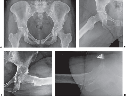 Figure 23.1. Standard radiographic views. A: Anteroposterior view of pelvis. B: Frog-leg lateral view of hip. C: Dunn 90-degree lateral view. The Dunn view optimizes visualization of the femoral neck and head–neck junction. As shown in this image, it can demonstrate abnormal bony proliferation and asphericity of the femoral head. D: Cross-table lateral view. |
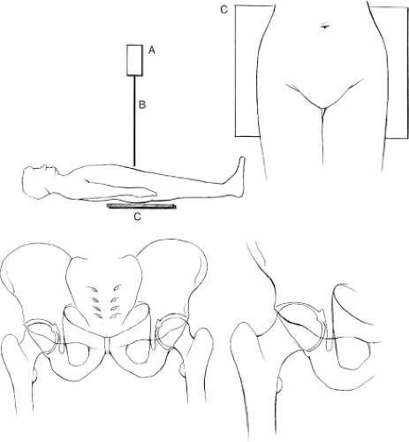 Figure 23.2. Anteroposterior (AP) technique for the pelvis and hip: x-ray tube (A), x-ray beam (B), and cassette (C). For the pelvic examination the beam is centered between the umbilicus and pubis, and for the hip it is centered on the ilioinguinal ligament between the anterior-superior iliac spine and pubis. By using standardized technique, the AP view enables the comparison of both hips and the assessment of acetabular morphology. |
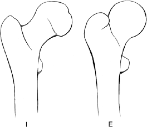 Figure 23.3. Representation of AP internal and external rotation radiographs of the proximal femur. In internal rotation the femoral neck elongates and the lesser trochanter becomes obscured, whereas in external rotation the greater trochanter overlaps the femoral neck and the lesser trochanter is more prominently profiled. |
AP pelvis views can be obtained with or without weight bearing. Weight-bearing images more accurately reveal joint space asymmetries and alignment abnormalities. For preoperative planning, the joint survey involves simultaneous acquisition of AP and, sometimes, lateral views of both lower extremities from the pelvic wings through the ankles. The joint survey improves understanding of the causes for alignment abnormalities and enables measurements of overall and segmental limb-length discrepancies.
Inlet and outlet views of the pelvis are acquired by directing the beam caudally and cranially by 40 degrees, respectively (Fig. 23.6). The inlet view best depicts the pelvic ring, including pubic rami fractures and rotational malalignments. The outlet view best demonstrates vertical malalignments.
Judet views are oblique images of the pelvis taken by rotating the patient at 45-degree angles and are most commonly obtained to evaluate for acetabular fractures following trauma or total hip replacement (Fig. 23.7). They may also help in assessing the position of the acetabular component in suspected protrusio. Different regions of both acetabula are imaged simultaneously on each of the Judet views. The anterior (iliopubic) column and posterior acetabular rim are best evaluated on the anterior oblique view, whereas the posterior (ilioischial) column and anterior acetabular rim are best evaluated on the posterior oblique view. Both Judet views are obtained for full evaluation of both acetabula.
Radiation Exposure and Relative Risk
In diagnostic radiography, the risks related to ionizing radiation are minimal but must be considered when ordering imaging examinations. Given the increasing levels of public awareness, patients more often ask radiologists and referring orthopedists to justify these examinations. Because doses are cumulative over a lifetime, the risk of developing radiation-related cancer is most significant in patients who have received relatively higher exposures before the age of 30 (3). Radiation risks decrease substantially in older patients.
There are numerous mechanisms for measuring and characterizing radiation dose in individuals. When referring to the biologic risks associated with radiographic and CT examinations, the absorbed dose and the normalized dose are expressed in standardized units. The absorbed dose is measured in rad or gray (SI unit) and describes the amount of ionizing radiation absorbed by specific tissues. The normalized dose is measured in rem or sieverts (SI unit) and quantifies the biologic effects of the absorbed radiation. The normalized dose varies for the same absorbed dose based on the organs exposed and the sensitivity of those organs to the absorbed dose (e.g., thyroid tissue is more sensitive than muscle to the effects of radiation).
Radiation doses for hip radiography typically amount to approximately 0.7 millisieverts (mSv) for two views of the hip and 0.6 mSv for an AP view of the pelvis (4). Table 23.1 serves as a reference of how these doses compare to other common exposures.
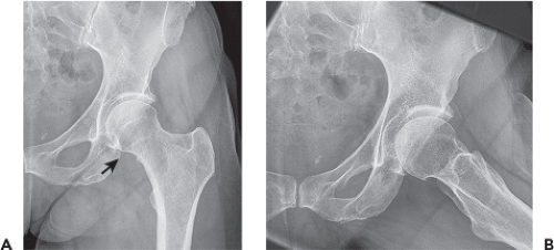 Figure 23.4. Femoral head–neck ring osteophytes simulating sclerotic fracture lines (arrow) in a 54-year-old female with long-standing groin pain and no history of trauma. A: Anteroposterior radiograph. B: Frog-leg lateral radiograph. |
Fluoroscopy and Fluoroscopically Guided Procedures
Fluoroscopy is commonly utilized in the operating room to guide instrumentation and confirm hardware placement. This real-time radiographic modality is also used to guide needle placement for several diagnostic and therapeutic procedures. Whereas fluoroscopy enables needle placement based on bone and joint visualization, sonography enables needle placement based on direct soft tissue visualization.
Fluoroscopy permits rapid access to the joint space of the hip and to collections that occur in predictable locations relative to bones, such as trochanteric bursal collections. Although sonography is more likely to be limited by body habitus and soft tissue mineralization, it can also permit accurate, rapid access to the joint space, juxta-articular collections and tendons.
Fluoroscopy permits rapid access to the joint space of the hip and to collections that occur in predictable locations relative to bones, such as trochanteric bursal collections. Although sonography is more likely to be limited by body habitus and soft tissue mineralization, it can also permit accurate, rapid access to the joint space, juxta-articular collections and tendons.
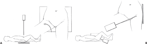 Figure 23.5. A: Frog-leg lateral technique with hip in flexion, abduction, and external rotation. The x-ray beam is directed anteroposteriorly and is centered on the ilioinguinal ligament between the anterior-superior iliac spine and pubis. The cassette is positioned posterior to the patient. B: Cross-table lateral technique. The contralateral hip is flexed to move it out of the way. The x-ray beam is directed in a slightly caudocephalad direction toward the cassette, which is positioned lateral to the hip. |
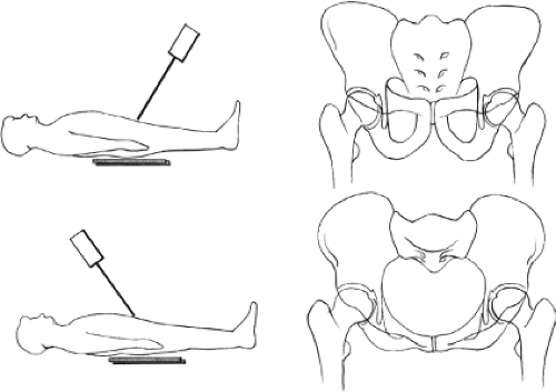 Figure 23.6. Outlet and inlet views of the pelvis. The outlet view (top drawing) is directed in a plane parallel to the rim of the pelvis and perpendicular to the sacrum. The obturator foramina are well visualized. Vertical malalignment is best assessed with this view. The inlet view (bottom drawing) is directed parallel to the anterior sacral cortex and demonstrates the pelvic rim. This view is best for assessing rotational malalignment. |
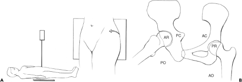 Figure 23.7. A: Judet oblique technique (right posterior oblique and left anterior oblique). The beam is directed in an anteroposterior direction and the patient is rotated 45 degrees. B: Representation of radiographic anatomy. Posterior oblique (PO) demonstrates the posterior column (PC) and anterior rim (AR). Anterior oblique (AO) demonstrates the anterior column (AC) and posterior rim (PR). |
Table 23.1 Typical Radiation Doses (mSv) (4) | ||||||||||||||||
|---|---|---|---|---|---|---|---|---|---|---|---|---|---|---|---|---|
|
Several fluoroscopic techniques can be employed to gain intra-articular access. C-arm units allow the radiation source and detector to be angled along any desired trajectory, thereby optimizing the success and safety of the procedure. With the patient positioned supine and the hip externally rotated, the C-arm is angled laterally from the straight AP axis until the beam profiles the femoral neck and greater trochanter (approximately 25 degrees). This anterolateral approach moves the needle entry site lateral to the groin and femoral neurovascular bundle. Using this technique, the needle trajectory is often so far lateral to the groin that it is unnecessary to palpate and mark the location of the femoral artery. Several fluoroscopic targets are feasible, including the lateral aspect of the subcapital femoral neck (Fig. 23.8). Slight flexion of the hip can help to relax the anterior joint capsule and facilitate intra-articular access. For most injections, a 22-gauge 3.5- or 5-in spinal needle is adequate. Intra-articular placement can be confirmed by fluid aspiration, loss of pressure resistance to injection or iodinated contrast instillation. Following hip arthroplasty, the prosthetic femoral neck can be targeted. If a non C-arm fluoroscopy unit is used, the patient can be angled on the table by positioning a sponge or pillow wedge under the ipsilateral hip. Otherwise, if a straight AP approach is necessary, care should be taken to palpate, mark, and avoid the femoral neurovascular bundle.
 Figure 23.8. A: Needle positioning for hip arthrography in a 33-year-old male who played recreational soccer and developed right anterior hip pain over months. B: MR arthrography. Coronal fat-suppressed T1-weighted arthrographic MR image shows contrast undercutting the superior labrum (arrow). Labral tear was proven at arthroscopy. |
Hip aspirations are often performed to obtain fluid from native or prosthetic joints due to suspected infection. Other inflammatory disorders might simulate sepsis. Fluid specimens can be analyzed for crystals in addition to gram stain, culture, pour plate, and cell count. Following arthroplasty, a 20-gauge needle may better facilitate aspiration compared to a 22-gauge needle because the stiffness improves passage through scar tissue, and caliber improves the sampling of thick fluid specimens. In the setting of a prosthesis, fluid is often more voluminous along the posterior aspect of the neck of the femoral component. This region can be accessed by sliding the needle posterior along the femoral neck, thereby increasing diagnostic yield (5). If a fluid specimen cannot be obtained, contrast can be injected to prove intra-articular needle placement.
Intra-articular injections are performed using similar needle placement techniques. In arthrography, contrast instillation precedes CT or MRI (Figs. 23.8 and 23.9). Intra-articular needle position can be confirmed with a test dose of iodinated contrast prior to the injection of 8 to 12 cc of contrast material (diluted gadolinium for MRI or iodinated contrast for CT, with or without added anesthetic agent). In MR arthrography, single contrast technique is important to avoid susceptibility artifact and poor anatomical resolution related to intra-articular gas.
A mixture of anesthetic and glucocorticoid is often injected for diagnostic and/or therapeutic purposes. Fluoroscopy or sonography can be used to guide needle placement
in the hip, iliopsoas bursa, or trochanteric bursa. Unless effusion is present, intra-articular needle position is first confirmed by a test injection of iodinated contrast material followed by the administration of the steroid solution. By combining beam collimation, pulsed radiation, and prudent fluoroscopy time with the appropriate lead shielding of reproduction organs, these procedures can be performed with extremely low radiation dose. Female patients in the childbearing age range should be asked about pregnancy. Risks related to bleeding, infection, and contrast reaction are all minimal.
in the hip, iliopsoas bursa, or trochanteric bursa. Unless effusion is present, intra-articular needle position is first confirmed by a test injection of iodinated contrast material followed by the administration of the steroid solution. By combining beam collimation, pulsed radiation, and prudent fluoroscopy time with the appropriate lead shielding of reproduction organs, these procedures can be performed with extremely low radiation dose. Female patients in the childbearing age range should be asked about pregnancy. Risks related to bleeding, infection, and contrast reaction are all minimal.
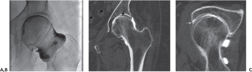 Figure 23.9. Single contrast CT arthrography of the hip. Pacemaker precluded MR. A: Single contrast arthrographic images prior to CT in a 74-year-old female with pain, weakness, and decreased range of motion. B: Coronal reformatted arthrographic CT image demonstrates focal cartilage loss (black arrow). C: Oblique axial reformatted arthrographic CT image shows anterosuperior labral tear (white arrow). |
Computerized Tomography
In this modern era, nearly all CT units are multidetector scanners and therefore acquire volumetric data sets that can be reformatted in multiple planes with comparable spatial resolutions. 3D reconstructions can be created from surface-rendered projections, volume-rendered projections, or maximum intensity projections (MIPs). These 3D objects can be rotated to depict osseous relationships and plan surgical treatments. 3D structures can also be manipulated to better demonstrate regions of interest. For example, by disarticulating the hip and removing the femur, the 3D object better reveals the acetabulum and the locations of acetabular fracture fragments.
Following traumatic injury, CT examination of the hip or pelvis can demonstrate suspected fracture or help in the characterization of known fracture for preoperative planning. CT images can show nondisplaced fracture fragments in the setting of negative radiographs when fracture lines are radiographically occult (2% to 10% of cases) (6,7,8,9,10). Whereas MRI is adequate in depicting stress fractures and marrow replacing lesions, small cortically based fracture fragments are not as well demonstrated (11). In the emergency departments of hospitals, where CT and MRI both are available, CT is the modality of choice in assessment of the traumatized hip and pelvis (12). The same CT scan that was used to evaluate the abdomen for internal organ injury can be used to create 2D reformations of the pelvis and 3D reconstructions of the hip.
As metal artifact reduction (MAR) techniques continue to evolve and improve, CT is requested more frequently to evaluate metallic implants and complications following arthroplasty. Hardware protocols and MAR techniques typically involve the use of higher kilovolt potentials (kVp) and milliampere (mAs) settings compared to CT scans performed for soft tissue evaluation. These protocols employ postprocessing algorithms that further diminish soft tissue contrast, but decrease the artifact associated with hardware. Metal artifact is more pronounced with stainless steel and chromium-cobalt alloys when compared to titanium due to higher x-ray attenuation coefficients. The beam-hardening artifact associated with these metals can be decreased, though not completely resolved, by utilizing iterative techniques with sharp kernels (13). Unfortunately, these techniques still require redundant and copious computing power and have the potential to introduce new artifacts that degrade anatomical detail and diagnostic potential. Dual energy CT (DECT) may also be used to decrease metal artifact. CT scanners with dual energy capabilities simultaneously perform scans at two different kVps (e.g., 140 kVp and 100 kVp) (14). The data from these simultaneous acquisitions are then postprocessed to achieve tissue discrimination, minimization of metal artifact, and enhancement of diagnostic information (Fig. 23.10). By adopting advanced MAR techniques, CT has become more valuable in evaluating implant alignment and bone stock as well as the complications of arthroplasty including liner wear, loosening, particle disease, and periprosthetic fractures.
CT Arthrography
MRI has been the primary imaging modality in the assessment of patients with suspected internal hip derangement and FAI. When contraindications (e.g., claustrophobia, pacemaker, cochlear implant, and intracranial aneurysm clip) or resource limitations prevent the use of MRI, CT reformations and 3D reconstructions facilitate the evaluation of osseous morphologic abnormalities such as hip dysplasia, acetabular retroversion, and abnormal offset of the femoral head–neck junction. In CT arthrography, iodinated contrast
outlines the acetabular labrum, articular cartilage, and joint capsule. Following single contrast arthrography and the direct intra-articular injection of iodinated contrast material, CT arthrography enables the diagnosis of acetabular labral tear, cartilage defects, and intra-articular loose bodies. Following the acquisition of axial images through the hip, multiplanar reformations can be produced in the same sagittal, coronal, and oblique axial planes as MR images, thereby yielding comparable diagnostic information about the acetabular labrum, articular cartilage, and joint lining (Fig. 23.9). As a work in progress, DECT algorithms can be modified to subtract iodinated contrast, yielding virtual arthroscopic images that reveal the contour of the acetabular labrum and the location of displaced labral fragments. This technique also aids in the detection and localization of loose bodies and cartilage defects (15). In patients with cemented hip implants, specialized DECT techniques under development may allow the differentiation of cement from contrast when attempting to confirm the leak of contrast along the cement–bone interfaces of prosthetic components.
outlines the acetabular labrum, articular cartilage, and joint capsule. Following single contrast arthrography and the direct intra-articular injection of iodinated contrast material, CT arthrography enables the diagnosis of acetabular labral tear, cartilage defects, and intra-articular loose bodies. Following the acquisition of axial images through the hip, multiplanar reformations can be produced in the same sagittal, coronal, and oblique axial planes as MR images, thereby yielding comparable diagnostic information about the acetabular labrum, articular cartilage, and joint lining (Fig. 23.9). As a work in progress, DECT algorithms can be modified to subtract iodinated contrast, yielding virtual arthroscopic images that reveal the contour of the acetabular labrum and the location of displaced labral fragments. This technique also aids in the detection and localization of loose bodies and cartilage defects (15). In patients with cemented hip implants, specialized DECT techniques under development may allow the differentiation of cement from contrast when attempting to confirm the leak of contrast along the cement–bone interfaces of prosthetic components.
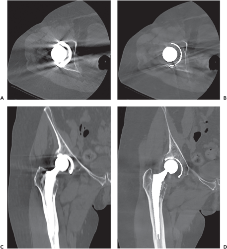 Figure 23.10. Dual energy CT in a 72-year-old female with hip pain status post arthroplasty. Comparing conventional (A, C) and metal artifact reduction (MAR) (B, D) postprocessing techniques, axial and coronal reformatted CT images demonstrate improved depiction of asymmetric liner wear with MAR, as well as periprosthetic osteolysis involving acetabulum and proximal femur. |
CT-Guided Biopsy, Treatment
CT is commonly used to guide percutaneous needle biopsy in the musculoskeletal system, including both osseous and soft tissue lesions (Fig. 23.11). Before performing the biopsy of
a suspected primary malignancy or metastasis, the interventional radiologist may consult with the patient’s oncologic surgeon to decide on needle trajectory in the event that the needle tract must be excised. At the time of biopsy, a preliminary CT scan is acquired at higher quality to confirm target location and identify neurovascular and other structures that must be avoided. A biopsy grid is placed on the skin to mark precisely the entry site of the needle. Table position and gantry angle are saved. Using sterile technique and appropriate anesthesia, a biopsy device can then be advanced into the target. Needle position is checked during advancement by sequential scanning. By obtaining only three to five slices at a time at reduced energy levels, radiation exposure during the procedure can be decreased substantially. Although the trade-off of energy reduction is decreased signal-to-noise ratio (SNR), these low-dose, lower-quality images are usually adequate for confirming safe needle placement and obtaining diagnostic specimens (Fig. 23.12).
a suspected primary malignancy or metastasis, the interventional radiologist may consult with the patient’s oncologic surgeon to decide on needle trajectory in the event that the needle tract must be excised. At the time of biopsy, a preliminary CT scan is acquired at higher quality to confirm target location and identify neurovascular and other structures that must be avoided. A biopsy grid is placed on the skin to mark precisely the entry site of the needle. Table position and gantry angle are saved. Using sterile technique and appropriate anesthesia, a biopsy device can then be advanced into the target. Needle position is checked during advancement by sequential scanning. By obtaining only three to five slices at a time at reduced energy levels, radiation exposure during the procedure can be decreased substantially. Although the trade-off of energy reduction is decreased signal-to-noise ratio (SNR), these low-dose, lower-quality images are usually adequate for confirming safe needle placement and obtaining diagnostic specimens (Fig. 23.12).
 Figure 23.11. In a 30-year-old patient with suspicious mass on MR (same patient as Fig. 23.18), CT-guided biopsy confirmed the diagnosis of myositis ossificans. A: Scout view shows skin grid for determining and marking the site of needle entry. The mass demonstrated faint, nonspecific mineralization. B: Axial CT image better exhibited peripheral mineralization suggesting myositis ossificans. C: The biopsy needle was advanced into the lesion to obtain a core tissue sample. |
CT guidance is typically used in radiofrequency ablation and cryoablation. Osteoid osteoma is treated primarily with high success rate (Fig. 23.13). Other small benign neoplasms, such as chondroblastoma and osteoblastoma, can be ablated. In patients who are not surgical candidates, ablation techniques can be useful in the palliation of painful osseous or soft tissue metastases (16).
Clinical Scenarios
Traumatic Hip Injury
In the initial evaluation and follow-up of hip fracture, well-established radiographic criteria are used in both diagnosis and the assessment of healing. The visualization of fracture lines, including resorption, sclerosis, and pseudoarthrosis, provides clues to the age of injury and the progression of healing. The degree of bony bridging can be difficult to determine, especially in the setting of internal fixation hardware.
Multiple classification schemes have been devised to categorize proximal femoral fractures. Fractures can be described anatomically based on involvement of the femoral head, neck, intertrochanteric region, subtrochanteric region, or diaphysis. Femoral neck fractures are subdivided into subcapital, cervical, and basicervical types. It can be difficult determining and describing the relationships between fragments. Besides position and angulation, rotational alignment abnormalities are particularly difficult to assess. More prominent visualization of the lesser trochanter, a posteromedial structure, suggests external rotation. Classification schemes can take into account avulsion-type fractures of the greater and lesser trochanters. Lesser trochanteric fractures are associated with metastatic disease. A displaced lesser trochanteric fragment raises the concern for pathologic fracture and may lead to further characterization by CT or MRI (17).
Related posts:

Stay updated, free articles. Join our Telegram channel

Full access? Get Clinical Tree


