Fractures
Sterile Instruments/Equipment
- Impervious stockinette and 4 inch elastic bandage wrap for arm, forearm, and hand
- Large and small pointed bone reduction clamps (“Weber clamps”)
- Threaded K-wires, and 2.5/4.0-mm Schanz pins for fragment manipulation
- Implants
- Anatomically contoured periarticular plates, consider locking plates for osteoporotic fractures
- Mini-fragment screws and plates for provisional/definitive fixation of metaphyseal cortical or tuberosity fragments
- Number 2 or larger non-absorbable suture for rotator cuff/tuberosity fixation augmentation, if required
- Fibular strut allograft (fresh frozen) for deficient medial column, if required
- Morcellized cancellous allograft bone, autograft, or osteobiologic substitute for metaphyseal bone defects (e.g., valgus impacted four-part fractures)
- Anatomically contoured periarticular plates, consider locking plates for osteoporotic fractures
- K-wires and wire driver/drill
Surgical Approaches and Positioning
- Positioning for percutaneous pinning/plating or for ORIF using deltopectoral approach.
- Supine with the patient reversed on cantilever radiolucent table (i.e., head and upper extremities at the cantilevered end of table).
- Consider small bump under the ipsilateral shoulder.
- Move the patient so that the head is at the proximal and lateral corner of the table, ipsilateral to operated extremity.
- Place the arm on radiolucent Plexiglas sheet (70 cm × 40 cm × 1 cm).
- Plexiglas is placed on the table, under the table pad and is supported by the patient’s torso.
- Approximately 1 ft of Pleixglas, protrudes beyond the table’s edge.
- Blankets or foam padding are taped to Plexiglas to match its height to that of the table’s padding.
- Plexiglas is placed on the table, under the table pad and is supported by the patient’s torso.
- Rotate table 90 degrees so that the operative arm faces the main operating space.
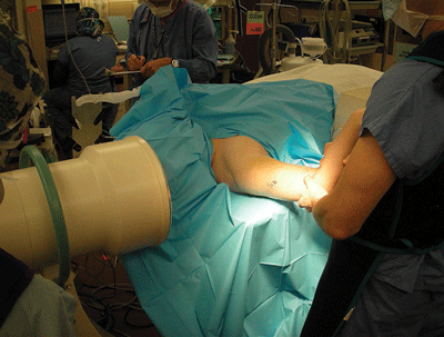
- C-arm should be placed at the head of the OR table to allow for axillary view with arm abducted 70 to 90 degrees (assess sagittal plane fracture alignment and plate position on humeral head and shaft) (Fig. 4-1).
- Supine with the patient reversed on cantilever radiolucent table (i.e., head and upper extremities at the cantilevered end of table).
Figure 4-1. With the patient moved to the edge of the table and the arm on a radiolucent extension, a reliable axillary view can be obtained intraoperatively.
![]()
- Positioning for deltoid splitting approach for intramedullary nailing of proximal fractures and for repair/ORIF of greater tuberosity fractures.
- Positioning for nailing
- Use Jackson table which is narrow in width and allows C-arm to come in from the opposite side.
- Scapular Y lateral view of proximal humerus is used instead of axillary lateral view, since arm cannot be abducted as implants (guide wire(s)/nail/targeting jig) interfere with acromion.
- Patient is positioned in center of the OR table, or slightly to the side of the injured extremity so that contralateral arm can be adducted to the patient’s side and rests on table top.
- No arm board is attached to the side of the table for uninjured upper extremity.
- This affords maximal C-arm excursion across OR table for AP/Grashey imaging views.
- Patient is supine with bump under the ipsilateral scapula.
- Either a foam wedge or folded blankets placed under both the shoulder and the hip can be used.
- Alternatively, place the rolls/wedge under the contralateral side.
- This rolls the patient’s body toward the side of injury allowing an AP C-arm image without the same degree of “roll back.”
- This accommodates the normal retroversion of the humeral head and anteversion of glenoid, thereby obviating external rotation of the arm for an orthogonal view of proximal humerus and glenoid.
- The scapular Y view is also improved in this position as long as the C-arm can roll forward, over-the-top far enough.
- This rolls the patient’s body toward the side of injury allowing an AP C-arm image without the same degree of “roll back.”
- Place the radiolucent Plexiglas sheet between the table and the cushion, under the patient’s torso and ipsilateral arm, protruding in long dimension approximately 4 to 6 inch to support arm in adduction if the patient is large or obese.
- This may not always be necessary in thin patients, as both upper extremities can be placed on the table adducted, next to the patient’s torso.
- C-arm rotates between 45 degrees roll back and 45 degrees roll over views to obtain orthogonal AP and scapular Y views, respectively.
- These views are important in confirming that the entry portal is collinear with intramedullary canal.
- If needed, a modified axillary view can be obtained by tilting the C-arm maximally such that the cathode (receiver end) of the image intensifier is near the patient’s head.
- This position looks like the C-arm position for a pelvic inlet view.
- The arm can be extended at the shoulder to facilitate an axillary lateral of the proximal humerus.
- This position looks like the C-arm position for a pelvic inlet view.
- If needed, a modified axillary view can be obtained by tilting the C-arm maximally such that the cathode (receiver end) of the image intensifier is near the patient’s head.
- Use C-arm to guide the location of skin incision in anterior-posterior and medial-lateral planes relative to ideal entry portal in proximal humerus.
- Either a foam wedge or folded blankets placed under both the shoulder and the hip can be used.
- Use Jackson table which is narrow in width and allows C-arm to come in from the opposite side.
- Positioning for nailing
Reduction and Implant Techniques
Stay updated, free articles. Join our Telegram channel

Full access? Get Clinical Tree


