Fig. 9.1
System components (blue) and interactions between them: (1) wide area data exchange, (2) bidirectional audio-visual connection in real time, (3) small distance wired or wireless connection, (4) visual feedback, and (5) wireless BAN sensors
Patient’s Home Station (PHS)—controls patient exercises in her/his home environment. It is the main data sink for the BAN and central processing unit at home. It provides connectivity to the PHR and audio-visual interaction between patient and therapist or clinician during training sessions.
Patient’s Interaction Board (IAB)—enables the patient to control the Home Station PHS and to perform exercises. It fits the movement impairment of the patient. PHS and IAB create a training place in patient’s living room.
Personal Health Record (PHR)—stores persistent data of entire processes in StrokeBack system at a central location, e.g., a web server. It can further be accessed remotely by the therapist for rehabilitation management.
Clinician’s interface (CIF)—offers to monitor the rehabilitation process and to access data for the Clinician. It is bound to the PHR as web interface and thereby accessible by any networked device, e.g., personal computers or tablet.
Therapist’s Workplace (TWP)—is installed in the clinic or therapists practice. It offers to schedule patient’s exercises and provide real-time supervision of the patient by the therapist and furthermore any kind of off line advisement, messaging and connection to the PHR.
Exercise and Compensation Tool (ECT)—performs an automatic evaluation of patients movement during training sessions. It monitors and evaluates training sessions automatically and provides feedback to patients without a therapist.
Body Area Network (BAN)—captures motion data of the patient without any local restriction and is suited for time periods outside the training sessions. It measures the transfer of movement skills from trainings session to daily life.
A detailed description of these components is given in the next subsections.
9.1.2.1 Patient’s Home Station
The PHS is located in the patient’s living room as part of her/his training place. To control the patient’s exercises in home environment, it needs multimedia output channels as speaker for audio signals and a screen for video signals. Both channels are used to give the patient three different stimuli: (a) a number of pointers how to execute correctly the exercise, (b) the information about the exercise and its options and (c) experience of motivation by playful tasks. The PHS gets multimodal feedback from the patient as the speech, the body gesture and the hand movements handling the training objects and while executing the exercises. Speech and body gesture are captured by the component itself while further inputs are given by the components IAB, ECT, and BAN. The PHS contains the following subsystems: a computer, front screen, microphone and speaker, controllable camera (with pan and tilt), and the network interface.
9.1.2.2 Interaction Board
This component is also located in the patient’s living room as part of her/his training place. The unit “Interaction Board” is a cluster of subsystems providing the patient’s interface for controlling the entire system. Furthermore, there is a display functionality to support the interaction. It is designed as universal input device for impaired persons. The patient should be enabled to handle the system in different modes. Those are the modes “Exercise,” “Session preparation” and “Communication.” For reasons of early and fast ability to work of the “Interaction Board” it may be delivered in different versions:
Version 1: The unit “Interaction Board” consists of the elements “Back Projector,” “Near-field Kinect” and “Kinect-Server.” The solution offers the maximum of adaptability, scalability, and functionality.
Version 2: The unit “Interaction Board” is emulated by a regular touch screen located horizontally as one unit and the “Near-field Kinect” subsystem.
Version 3: The unit “Interaction Board” is emulated by a tablet PC.
Game handling is managed by the “Interaction Board” unit (providing graphical content plus touch event) via Kinect-Server to “Event Controller” in main computer.
The “Event Controller” provides the interface between the HID (Human interface device, i.e., mouse or keyboard) and the game. The “Event Controller” would transform any Ethernet datagram into HID-event. The games could be tested temporarily by mouse or keyboard. The data flow in the Home station includes:
1.
Raw data from element “Near-field Kinect” and “Far-field Kinect” to be processed by the Kinect-Server for the Interaction Board or by the OpenNI Framework and Microsoft Kinect SDK for calculating “skeleton stream” data for the ECT.
2.
Capture of objects, fingers, etc., by the “Near-field Kinect” unit and transmission to the main computer with a rate of 50 per second via IP datagrams. They ensure the response of game logic to movements.
3.
Messages sent from “Expert system” via IP datagram enable the system to display messages to the patient generated by the artificial advisor system. Furthermore 3D coordinates and orientation data of body joints with a rate of 50 frames per second are transferred for calculating a vector-based, 3D representation model of the patient’s upper body.
4.
Video data to screen (VGA or HDMI). It is controlled by the main application displaying PHR-content, Game-content, or management content in the work place and/or the front monitor.
5.
Temporary connected BAN transfers the raw or pre-classified sensor data from BAN nodes for the evaluation of daily living behavior to the subunit “Main computer” for pre-processing and uploads to PHR.
9.1.2.3 Personal Health Record
The PHR stores all patient-related data necessary to manage an entire rehabilitation process after stroke. The following components exchange data with the component PHR: Clinician Interface, Therapist Work Place, and Patient Home Station. No clinical or personal data is stored anywhere else, but the PHR with firm data security.
9.1.2.4 Clinician’s Interface
The CIF consists of a regular PC with web cam and head phone and Internet connectivity. The physician communicates with the PHR and with the devices during clinical assessment.
9.1.2.5 Therapist’s Workplace
The therapist’s station consists of a regular PC with web cam and head phone and Internet connectivity for access to the PHR. The therapist uses specialized software to communicate with the patient for remote supervision sessions.
9.1.2.6 Exercise and Compensation Tool
The exercise evaluation tool provides automatic real-time supervision of rehabilitation exercises. It allows to record and monitor individual exercises to evaluate the correctness of exercises and compensational movements made during the training sessions. It will be individually trained/configured by the therapists for certain patients to fit the individual clinical requirements.
This tool decouples the therapist from time consuming observation of patient’s exercise and empowers the patient to train alone and individually in preferred way and time. It generates messages for the component “Patient’s Home Station.” It is software processing skeleton data from Kinect to evaluate execution of exercises. Generated feedback messages should be simple and plausible. They may be spoken via speakers and/or written on the main video screen.
9.1.2.7 Body Area Network
The BAN consists of wearable sensors with data storage facility and a wireless receiver. The BAN sensors can be configured to proper data acquisition rate. The prototype of a very small and lightweight BAN node is shown in Fig. 9.2.
Fig. 9.2
Photo from sensor node case in comparison to a 2-Euro coin (a) and a schematic view of the case (b) taken from www.okw.com
Each sensor processes and stores sensor data in real-time and may perform data compression to reduce data storage requirements. Data will be gathered by the BAN over a fixed period depending on estimated battery life or patient’s needs. Recorded data of each session will be transferred to a PC (PHS or TWP) while charging batteries, e.g., in a docking station. Sensor data will be analyzed and classified to determine characteristic patterns that are associated with particular movements to generate movement statistics on daily basis. The BAN captures motion data during daily life of a patient. It is used to document transfer of motion abilities regained in training sessions. It logs data and transmits it to the PHS in regular intervals, where it is analyzed before results are stored in the PHR. It should work nearly invisible and must not hinder the patient in her/his daily life activities.
9.2 Design of the Prototype System
This section describes preliminary implementation of the components in hard- and software. The patient’s training place at home is composed by the components “Patient’s Home Station,” “Interaction Board” and the “Exercise and Compensation Tool.” The design considers the situation in patient’s living room. For technical reasons the mentioned components are needed and should be positioned inside the living room. However, they should not hinder the patient and its relatives and should not occupy more room than absolutely necessary. Bear in mind also that equipment might be rented by the patient, i.e., it may be transported from one patient to another. The identified requirements resulted in assembling all components on one work table trolley. This means that:
All the components are available on the work place of the patient
Existing furniture’s not need to be occupied
Required volume of equipment is reduced to a minimum
Work place can be easily moved to a different room of the patients home
Equipment installation and maintenance may be offered by service providers
9.2.1 Work Table Trolley
9.2.1.1 Schematic View
The patient sits in the chair (or wheelchair) at the work table trolley. Chair and trolley can be adapted to the needs of the individual patient. His/her body posture should be optimal for monitoring by sensors and/or camera. The table trolley must be equipped with immobilization brakes and the option to adjust the table height, preferably during installation phase. Adjustment to table height can be done using dowels steps. Table design must prevent it from falling. Its size should fit to the free place in a regular living room. As a first approach, the size of 800 × 1000 mm is fixed. The depth of 800 mm is needed for positioning of vertical computer screen. The width of 1000 mm is needed for positioning of the near-field motion tracker.
The motion tracking of hands and training objects must be available to (1) support exercises, (2) to evaluate movements during exercises and (3) to provide a comfortable Human—Machine Interface (HMI) for the patient. The design of comfortable HMI for the patient considers his/her impairments controlling the “Patient’s training place” by movements. Such functionality is provided by the unit “Motion Tracker” represented in the first approach by the commercial product “Kinect,” used in near-field mode, and the “Kinect-Server.”
The “Kinect-Server” subsystem reduces the data stream sent by the commercial product “Kinect” to few essential messages and skeleton ankle positions. The output of the unit “Motion Tracker” is formatted specifically, so that a transmission to the component “Patient’s Home Station” is feasible. It is intended proposing a communication standard between training devices and the PHS in the framework of homely rehabilitation equipment. The mentioned concept considers optionally developing further kinds of interaction boards or training devices in the future, which then may communicate via that interface with the PHS as well.
Patients interact with the “Patient’s Home Station” via three different user interfaces: a video screen, a graphical display of the “Interaction Board” and audio (microphone and speakers). The main video screen displays information regarding a choice of exercises, the configuration of exercises such as level of difficulty, the type of sounds, and other adjustments preparing the exercise. During live communication, the face of therapist or physician may be displayed on the main screen. The live communication can be combined with exercises motivating the patient and suggestions by therapist in parallel. Both tasks of remote care are essentially to keep the motivation of the patient high and to avoid wrong movement learning.
During training, the state of exercises and scores are displayed. Content of exercises and the graphical representation of tasks can also be displayed on the interaction board. Graphical information must not be presented on both channels in parallel to avoid too complex tasks and irritation while concentrating on both screens. At the end, the kind of exercise practically identifies where the main content is displayed: Exercises for hand rehabilitation and tasks with real training objects will be displayed on the interaction board. Exercises with virtual reality involving whole upper body parts will display their content on the main screen. The speaker outputs the speech in live communication with the advisor and the sound of exercises, i.e., music or spoken commands.
The “Patient’s Home Station” (shown in Fig. 9.3) receives information about the patient from four different sources: microphone, pan tilt zoom camera, body motion from far-field Kinect sensor, while and limb motion and object capture from the near-field Kinect.
Fig. 9.3
Schematic drawing of the “patient’s training place”
The microphone is used for the live communication with therapist or physician. The PTZ camera can be used to observe movements of the patient during live communication sessions. The live communication between patient and therapist currently is a key issue in state-of-the-art remote care [2]. In the mentioned project the live communication encloses suggestions of the therapist immediately whilst the exercise is performed by the patient.
However, such approach requires more or less equal time of therapists as in real visit. Overcoming such drawback, the component “Exercise and Compensation Tool” is added. This unit automatically evaluates current movements and exercises to signal changes or failures to improve patient performance similar to real trainings with therapists. This feedback is based on capturing motion of the entire upper part of the body. The unit contains “Far-Field Kinect” and “Expert System” units. The latter one generates feedback for the patient based on motion capture and transmits feedback messages from the component “ECT” to the “Patient’s Home Station” unit, where these are put out via speakers.
9.2.1.2 Implementation
The look and feel of the “Patient’s training place” is shown in Fig. 9.4 from the perspective of the work table and showing the patient’s training place in Fig. 9.5.
Fig. 9.4
Schematic drawing of the design of the patient’s training place
Fig. 9.5
Preliminary design of patient’s training place, patient’s view
The main issue of medical rehabilitation after stroke is the huge extend of training to regain movement capabilities of the patient. More than 40,000 repetitions of meaningful movements are necessary to percept a success as patient. To encourage the patient continuing the training, a complex form of motivation management is indispensable. The StrokeBack system uses three methods for increasing patients’ motivation:
1.
Personal contact between patient and therapist
2.
Feedback in real time
3.
Connection of gaming and learning
The personal contact between patient and therapist is quite common in the setting of occupational therapy. The tele-rehabilitation replaces the physical contact with audio-visual experience of a joint talk. However, it is a talk about the currently performed physical activity. Simultaneous activities, talking and moving, enlarge the effect of the conversation in the sense of unconscious learning.
Since the patient must keep on training regularly to improve the motion capabilities, the exercises have to be interesting and motivating. To meet such goal, the “Patient’s training place” should allow presenting different exercises in different outfit with different training objects or training devices.
The feedback for the patient has to be presented in real time through different channels. There is the graphic presentation, the output of music, and the linguistic or written presentation of messages and the evaluation of the performance by scores. Three types of scores are used to:
1.
Motivate the patient
2.
Substantiate the individual progress for patient’s health record
3.
Prove differences between therapy approaches for scientific evaluation
The scores of type (1) should be comprehendible for the patient. The scores of type (2) and (3) should possess a clinical meaning. The design and formulation of appropriate scores is a continuing task during the project work. The process considers knowledge from rehabilitation medicine, from motivational theories in psychology and from statistics.
There are a set of biomechanical and functional parameters serving as the start point for further development. The aspects of sensitivity and selectivity play a big role selecting or creating the scores. From technical point of view, a hierarchical organization of scores offers all opportunities to improve the scores at any time.
9.2.2 Patient’s Interface “Interaction Board”
The “Interaction Board” used by patients is shown in Fig. 9.6 with “Video screen” at the top and the emulation of the “smart table” below.
Fig. 9.6
Prototype implementation of the “interaction board”
Its user interfaces may be implemented in different versions, such as:
Version A: The “Interaction Board” consists of “Glass plate,” “Motion Tracker,” “Kinect-Server,” “Video Controller,” “Back Projector” and “WLAN” units. This solution offers maximum adaptability, scalability, and best range of functionalities.
Version B: The “Interaction Board” is emulated by a regular touch screen located horizontally as one unit and a mini-PC containing “Touch screen,” “Video Controller,” “Touch Controller” and “WLAN.”
Both versions support the feasibility and the early opportunity to test the system. Both versions offer best compromise between the scalability of the solution and its costs. They also do not require much space and can be considered as a mare extension of the regular living room of the patient’s home.
From implementation point of view both versions offer different set of capabilities:
Version A: The “Interactions Board” consists of a glass plate as half transparent back projection screen, a mini projector with controller and the unit “Motion Tracker.” The visual content is received by the unit “WLAN” and sent to the mini projector via the video controller. The projection is executed from below against the glass plate serving as work area for the patient. The training objects are located on the glass plate where the exercise is executed. The unit “Motion Tracker” is located above the glass plate on the right or left side and must not hinder the exercises of the patient. The unit “Motion Tracker” creates a volume model of the hand and the training objects and identifies collisions between the hands and objects as well as the glass plate. The collisions are messaged as touch-events to the component “Patient’s Home Station.” Currently the functionalities of the “Motion Tracker” are offered by the modified commercial “Kinect-Server.”
Version B: The “Interaction Board” is assembled by a regular touch screen located horizontally as one unit and a mini-PC containing the “Video Controller,” “Touch Controller” and “WLAN.” Instead of the 3D coordinates of hand and training objects, only the horizontal position is available. The assembly is cheaper than the version A and needs less space. The current realization of such assembly needs the width 530 mm, the depth of 420 mm and the height of 50 mm, see lower part of Fig. 9.5.
9.2.3 Patient’s Home Station
The “Patient’s home station” controls the interaction between the patient and the StrokeBack system. Graphical symbols displayed on video screens, the front screen, and the interaction Board are main parts of the user interface. The exact distribution of visual content among “Video-Screen” and the “Interaction Board” depends on the actual task. The following tasks are supported:
1.
Selection of exercises: a list of supposed exercises is displayed on front screen. The Interaction board displays the control to select the wished items and tasks.
2.
Configuration: allows choosing a level of difficulty, type of sounds and setting related to live communication with the therapist. The Interaction board displays a list of supposed items and provides controls to select the wished item.
3.
Execution of training: two types are considered, using virtual and real objects:
(a)
Virtual objects: objects are displayed on the front screen. The interaction board displays instructions and controls to adjust the exercise course.
(b)
Real objects: current state and scores are displayed on the front screen. The graphical illustration of tasks is displayed on the interaction board.
4.
Live communication: Enables execution of bidirectional audio-visual live communication with therapist or physician.
The “Patient’s home station” controls the audio output for the patient, which comes from exercises as messages, songs, sounds, or directly from live communication. Furthermore the unit “Patient’s home station” controls the data exchange with the components “BAN” and “PHR.”
9.2.4 Therapist’s Workplace
The work place of therapist is designed to support the use cases in its entire granularity. As hardware component a multimedia PC with internet connectivity is thought to be sufficient. The software was designed as a local application integrating browser capabilities. It includes an administration console implemented as a WEB page, embedded into a PHR server.
The “selection of Patient” page of the PHR embedded into a therapist’s view is shown in Fig. 9.7, while Fig. 9.8 shows the live video of a patient doing the exercise. The live video of the Therapist appears on the left of the windows. The buttons enable therapists to select different tasks.
Fig. 9.7
Therapist’s view to the page “selection of patient” of PHR
Fig. 9.8
Therapist’s view while the patient executes exercises
The therapist can observe how patients executes their exercise and to comment immediately on any wrong movements. He can also see a statistics of exercises performed (Fig. 9.9) and/or see live videos with all patients together (Fig. 9.10).
Fig. 9.9
Therapist’s view during exercises: showing scores (left)
Fig. 9.10
Therapist may advice different patients at once
9.2.5 Work Place for Clinical Assessment
The workplace used for a clinical assessment is built from a laminated surface with marked distances for the placements of objects (refer to a schematic in Fig. 9.11).
Fig. 9.11
Schematic view of WMFT surface
In addition, a couple of objects, such as checkers, cards, an ordinary lock, etc., are needed to execute different tasks. Photos of the surface are given in Fig. 9.12.
Fig. 9.12
Photos from laminated surface used for WMFT test task, e.g., using a key lock (a), checkers (b), or cards (c)
9.2.6 Data Flow
The main components and their data exchange scheme are given in Fig. 9.13. Rectangles represent components, arrows show data paths, circles indicate references to the description of the data content, detailed in Table 9.1.
Fig. 9.13
Data flow between main components of system “StrokeBack”
Table 9.1
Overview of main paths for data exchange
Path no. | Source | Unit | Purpose | Use case |
|---|---|---|---|---|
1 | Therapist station | PHR | Transmits therapist’s ID Selects the patient Starts a session as a therapist Gets information about the patient Composes and schedules training Reads earlier training sessions | 1 |
2 | Patient training | PHR | Starts the session as a patient Receives info about exercises (games) BAN data about earlier daily activities | 4 |
3 | Patient training | Therapist station | Starts a session with supervision Transmits bidirectional live link Sends messages controlling exercises Sends current exercise performance data | 2 |
4 | BAN | Patients training | Sends data about past daily activities Transferring data to PHR | 3 |
5 | Physician station | PHR | Sends physician’s credentials Selects a patient Starts a session as a physician Gets information about a patient Transmits evaluation results | 1 |
9.2.6.1 Data Flow Between “Therapist’s Station” and the PHR
To get access to the PHR, the therapist’s credentials are transmitted in an authentication process. This initiates a session for the therapist. The therapist will then select a patient and study the actual and recent training results to determine the patient’s current needs. Based on protocols from passed training sessions, the therapist may compose and schedule future training sessions of the selected patient.
9.2.6.2 Data Flow Between “Patient’s Training Place” and PHR
The patient logs into the PHR to start a training session and receives information about his/her training schedule, exercises, scores, results, and messages if available.
9.2.6.3 Data Flow Between “Patients Training Place” and “Therapist Station”
This data exchange is initiated via the PHR to start a scheduled training session with supervision. It transmits bidirectional audio–video streams and transfers messages and scores to modify the exercise level and analyze exercise performance.
9.2.6.4 Data Flow Between BAN and “Patients Training Place”
The BAN transmits motion data that is analyzed to determine statistics of passed daily activities. Respective results are stored in the PHR automatically. The patient does not need to initiate this process. All data exchanges are managed autonomously by the BAN and PHS without being triggered by the patient.
9.2.6.5 Data Flow Between “Physician’s Station” and PHR
This is similar to the data exchange between the “Therapist’s station” and the PHR. It transmits the physicians ID, allows selecting a patient, study training protocols, starting sessions, and uploading evaluation results.
9.2.6.6 Data Flow Within the “Patients Training Place”
This paragraph describes the data flows between the main components in the patient’s home station that is depicted in Fig. 9.14. There, blue and gray rectangles specify subsystems and their respective elements whereas green rectangles determine user interface elements. The arrows represented directed data flow. The numbered arrows in Fig. 9.14 correspond to the following data flows:
Fig. 9.14
Data flow in patient’s training place
1.
Raw data from elements “Near-field Kinect” and “Far-field Kinect” to be processed by the Kinect-Server for the Interaction Board or by the Open NI Framework and Microsoft Kinect SDK for calculating “skeleton stream” data for the ECT.
2.
Coordinates of objects, finger and hand movements from unit “Near-field Kinect” to main computer with a rate of 50 items per second. These data is required to analyze movements and calculate input for the game logic.
3.
3D coordinates and orientation data of body joints with a rate of 50 frames per second are transferred for calculating a vector-based, 3D representation model of the patient’s upper body. It is used to control correct execution of exercises and determine compensational movements.
4.
Video data to screen (VGA or HDMI). It is controlled by the main application displaying PHR-content, Game-content, or management content on the interaction board and the front monitor.
5.
BAN nodes transfer raw or pre-classified sensor data for the evaluation of ADL behavior to the “Main computer” for processing and the upload to the PHR.
9.2.7 Detailed Use Cases and Actions
There are characteristic sequences of actions for all mentioned users. Every single action refers to a “use case” with regard to software development. There exist interdependencies between actions of users, i.e., an action of one user may be required before other users may continue their actions. To keep it simple, the isolated sequences of main actions are presented only. Any action may be disassembled into more fine-grained activity steps described in the following paragraphs. The following activity steps could be identified in a more granulated manner:
Initial assessment in clinical environment
Execution of test tasks
Motion capturing
EMG Measurement
Execution of training sessions at home
Patient switches on the training device.
Patient starts a “Tele-rehabilitation”-session using the interaction board.
The patient may select between “autonomous training,” i.e., without real-time connection to the therapist, or “with supervision.” In case of no supervised training is scheduled or there is no connection to internet, the “autonomous training” mode is selected automatically.
The patient selects an exercise and starts it. She/He may consider former training scores and adjust the difficulty level. Some exercises may be accompanied by user-selectable music. All actions follow a set of permissions that have been configured by the therapist before.
The patient executes the exercise in the autonomous modes. The PHS monitors and analyses the execution of tasks and exercises and generates respective feedback. Training results and scores are then sent to the PHR.
The patient executes the exercise with live-supervision by the therapist. She/He is observed by the therapist, may see the therapist on the screen via bidirectional video communication and may receive real-time guidance.
The patient can see the exercise evaluation and score after finishing it.
9.2.8 Detailed Actions of a Therapist Within Use Case 4: “Remote Care”
The following actions are performed by the therapist:
Action 1: Schedule training for a patient
Study the patients’ health record
Compose training schedule by selection of predefined exercises
Configure exercises and difficulty levels
Schedule meeting dates and supervised training sessions with the patient
Action 2: Real-time supervision
Observe the patient
Support the patient via verbal comments
Demonstrate intended movements and exercises via video link
Adjust the exercise level to the actual shape and mood of the patient
Action 3: Training Evaluation
Evaluate the training sessions
Check the scores
Comment on sessions and storage of reports
Action 4: Remote consultation
Respond to alerts or training results
9.3 Final Implementation
The StrokeBack system addressed two primary types of users i.e., patients and therapists or care persons respectively. It is quite obvious that both user types must not be confronted with any technical duties and tasks. Therefore the system had to be self-explanatory and self-calibrating up to certain level, e.g., a fixed training place should be able to recalibrate or reconfigure autonomously with minimal intervention of the users.
From the patient’s point of view, the usability of hardware components of the StrokeBack system, especially when used at home without on-site therapists, is the most crucial point to be sorted out. Currently, the most challenging tasks will be: How to enable ease of use when sensors need to be attached to the body by the patient herself? How to determine, or make sure respectively, that the sensors will be at the right positions? Different ideas have been discussed already. For example, a wrist band such as used for wristwatches should be a proper means to attach sensors to the wrist of the arm under monitoring. However, means that aren’t easy to handle for the patient, or that need assistance from a care person, are to be avoided wherever applicable. Here, the consortium will rely on hands-on knowledge gathered in previous projects. Necessary approaches were agreed as soon as first technical experiments allowed a detailed analysis of a technical architecture and components used. A close work with therapists in early experimental phases allowed to determine proper and smooth ways of integrating devices in patients’ daily routines.
Furthermore, designs of user interfaces regarding the look and feel of the system and the graphical representation have been discussed. Currently, the system provides a touch screen display with a simple GUI for patients composed of large, color-coded icons. The four sections are represented to patients with big buttons:
Exercises/Training—The patient should use this section to initiate and select training sessions and exercises. It will feature a graphical representation of the rehabilitation plan that is to be configured by the therapist. It will most probably allow configuring training sessions on daily basis with an integrated calendar function. This enables to integrate reminder messages and audio-visual reminder functions as well.
Feedback—In this section the patient can have a look at previous training sessions, results, high scores in games, and rehabilitation progress.
Messages—This enables the therapist to send messages to the patient. Messages can be sent by the therapist only to provide feedback and encouragement for example. It is explicitly planned as one way communication. It will not allow patients to communicate actively with the therapist to avoid a mass of unnecessary and not manageable messages.
Video Session—We will optionally integrate means for audio-visually guided training sessions in the system. These are to be configured and used on behalf of the therapist only. Experiences from previous projects have shown that many patients desire such functionality.
In general, any data given to the patient should be high-level data with minimal details and should preferably be presented in graphical and/or audio-visual way. Similarly, data accessible by the therapist should also be simple data but on a more detailed basis. Therapists will have access to timesheets, training results, and rehabilitation progress in more detail, e.g., being able to figure out number and quality of single exercises. However, end users will neither gain access to raw sensor data nor to interim values or algorithms. The main design rule is: Keep it simple!
The technical design guidelines based on experiences from previous projects, various system approaches, and use cases have been reviewed and assessed for drafting the StrokeBack architecture.
9.3.1 Evaluation of the Overall Design
The first drafts of the architecture and requirements, allowed for use cases and lists of components required for each use case to be selected. Furthermore, aspects of look and feel of the StrokeBack system and its integration into patient’s home and life have been incorporated into the design. As a result of further investigations regarding minimum distances between patient and the Kinect cameras, a prototype of the patient home station has been produced. This has been used as initial reference system for parallel developments of all subsystems.
Several instances of serious games have been tested and improved according to the feedback from therapists and patients. The same holds true for development of the PHR interfaces, the Exercise and Compensation Analyse (ECA) tool from UP and the user interface of the patient station. With respect to the events specified for controlling the rehab games, the event capturing algorithms has been developed using a near-field Kinect focussing on wrist movements and palm opening/closing as these have been identified by the physicians as key objectives for successful rehabilitation of the post-stroke patient (refer to Chap. 7).
While integrating both main Kinect-based subsystems ECA tool and wrist movement capturing, the performance of the near-field Kinect system decreases significantly when both Kinects are used in parallel. Hence, we need to merge both implementations to work with one Kinect only if possible. Therefore the patient home station will integrate one Kinect device only.
Finally, the empirical evaluation of the assembled Patient Station and its respective workflow commenced with the design of the patient station with a vertical and a horizontal screen. A training cycle is offered to the patient as shown in Table 9.2.
Table 9.2
Typical training cycle at patient home station
Step | Description | Vertical monitor | Horizontal monitor |
|---|---|---|---|
1 | Switching the Rehab Table on using the main switch | Welcome screen and a list of patients registered on the Rehab Table (clinical device only) | Welcome screen and the list of patients registered on this Rehab Table (clinic device only) plus the button “Start” |
2 | After touching the “Start” button on the horizontal monitor | Welcome screen remains | Four buttons of main menu: |
“Exercise”, “Feedback”, “Help”, “Video-Session” | |||
3 | After touching “Exercise” button on the horizontal monitor | The text “Select an exercise” | Buttons to select the exercise depending on the configured training unit |
4 | Select an exercise on the horizontal monitor → exercise is launched | Exercise content (game) | Control keys of the selected exercise (if necessary) + “Quit” and “Help” buttons |
5 | Exercise stopped by pressing the “Quit” button on the horizontal monitor | ||
6 | Start of video link with the therapist by touching “Video-Session” button on the horizontal screen | Smaller image from the local camera left above and a larger image from the remote video camera right sites | Four buttons of main menus: “Exercise”, “Feedback”, “Help”, “Video-Session” |
7 | Request feedback: by touching the “Feedback” button on the horizontal monitor | Feedback in graphical form | Button “Back/Quit” |
8 | Request help: by touching the “Help” button on the horizontal monitor | Textual advise, video, or no change (depends on previous content) | Textual advice and the button “Messages” |
9 | How to switch off the rehab table completely? | All interfaces enclose a “Finish” button at all time |
Since the first prototype of the mobile patient station was quite large and heavy, thus a second much smaller variant has been designed. Photos of both variants are shown in Figs. 9.16 and 9.17, respectively. The first prototype is based on the design of the stationary device in the clinic, while the second one adds few technical improvements. In particular, near-field Kinect was removed with a leap motion sensor taking over monitoring/recognition of hand movements. This allowed to get rid of the second computer inside the horizontal part of the device lying on the desk. In total, the size of the mobile station has been reduced by 30–40 % and the weight reduced by 50 % as well. Please note that the sizes of the displays used in both variants are equal, as this might not be distinguishable in the figures.
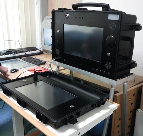
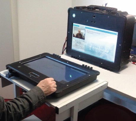
Fig. 9.16
First prototype of mobile patient station for home use
Fig. 9.17
Second prototype of mobile patient station for home use
9.3.2 Specification and Implementation of Selected Rehabilitation Trainings
The functionality of exercise monitoring tool has enabled the monitoring of the whole upper body of a person instead of single limbs only. Instead of calculating position of body joints and angles between adjacent body parts, the evaluation tool can calculate complete 3D vectors of each body part including length and direction of those. This enables a much more precise modelling of the upper body. A tool for real-time supervision of simple, non-complex exercises is already available. It allows to record and monitor individual but simple exercises. This tool has been re-implemented for usage on window platforms, which has been chosen as the basic programming environment for the StrokeBack system. It has been further extended to support parallel multi-exercise monitoring of previously recorded exercises.
In addition to the modelling and evaluation of correct execution of therapeutic exercises, a tool to detect unwanted or not-allowed movements during training sessions, called compensational movements, is developed. This is especially desirable from the therapeutical point of view. In a real-life training session, normally the therapist pays attention to unintentional movements and corrects those, e.g., leaning forward or movement of the shoulder. In StrokeBack, the monitoring systems should do this automatically. Hence, we investigated a library of compensational movements that need to be monitored during normal execution of exercises. Therefore we have worked out an overview of compensational movements that commonly appear during training with stroke affected patients. A first version of this tool that detects compensational shoulder movements. In the very end, both tools would be merged into one tool, called Exercise and Compensation Analyse.
Related posts:


Stay updated, free articles. Join our Telegram channel

Full access? Get Clinical Tree


