Fig. 18.1
Contact stress patterns across the surface of the proximal tibia at 14 % of the gait cycle show that load is distributed across both tibial plateaus but varies as to magnitude and location [Artwork courtesy of Hongsheng Wang, Ph.D.]
Consider the knee joint. Its bicondylar geometry, combined with the anisotropic, inhomogeneous properties of the articular cartilage and the menisci, and the variation in properties that occur among the normal patient population [4, 5] and even within a specific knee over time make understanding load transfer a complex endeavor. Forces perpendicular to the joint surface can be measured experimentally [6], but to understand how those forces are transferred through the articular cartilage to the underlying bone and out to the cortex requires the use of computational finite element models. Elegant models have been developed that capture the biphasic response of the soft tissues of the knee [7] and the inhomogeneity of the natural knee [8], but few efforts have focused on how alterations in tissue geometry and material properties affect load transfer. Segal et al. [9] explored the association between knee joint contact stress magnitude in patients identified as being “at risk” for the development of OA. They found that elevated contact stress was a predictor of subsequent cartilage damage and bone-marrow lesions, but a direct connection between the stresses in the tissues and subsequent tissue damage was never made. As more research focuses on how knee injuries affect surface contact stresses, additional efforts will be required to make the connection between how the resulting changes in load transfer influence the underlying tissues [10]. Without such an analysis, a direct connection with the pathogenesis of post-traumatic arthritis is purely speculative.
The Influence of Joint Loads
The magnitudes of the loads that are transferred across joints in the skeleton are high, even during normal activities of daily living. Direct measurements of joint loads have been performed in the knee and hip joints through the use of instrumented total joint replacements. For the knee joint, in vivo loads exceed 2–2.5 times the body weight for activities like walking, climbing stairs, or swinging a golf club [11]. Similar results were found for the hip for these same activities, though loads reached as high as 8.7 times the body weight during an unanticipated stumble [12].
In one respect, alterations in joint loading as they pertain to PTA can be considered on the basis of changes in load magnitude alone. Such an approach, understanding how increased magnitude affects the propensity for arthritis to develop in the joint, is fruitful because the mechanical factor, load magnitude, can be easily controlled in experimental models. Consequently, numerous animal models have been developed to characterize the mechanical effects of blunt trauma as an extreme alteration in load magnitude. In these models, trauma is induced by directly impacting the articulating surface of the joint with a rigid indenter. Altering the radius of curvature of the indenter (e.g., flat versus curved) can be used to vary the load distribution and hence the applied stresses for the same magnitude of applied traumatic load. Tissue alterations as a result of the blunt trauma can then be assessed as a function of the time after impact.
As expected, studies with blunt trauma models show that a relationship exists between matrix damage and the magnitude of the contact force (Fig. 18.2) [13] and that the extent of cell death in articular cartilage is significantly affected by the magnitude of applied contact stress [14]. Perhaps more importantly, subsequent consequences of alterations in load magnitude and distribution are revealed through mechanically driven adaptations in tissue quality (composition and structure). These include decreases in cartilage modulus and subchondral bone thickening that begin immediately after impact and persist out to 36 months after the trauma [15, 16].
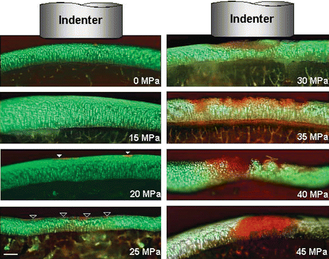

Fig. 18.2
Microscopic images of cross sections of the articular cartilage in the impacted and surrounding regions [taken from reference 12]. Shown are the full thickness of the articular cartilage and a thin layer of subchondral bone. Green stain indicates viable and red stain indicates dead cells. Cell death initiated at the surface in locations that corresponded to the edges of the indenter (solid arrows). The cell death was evenly distributed on the surface (superficial region) in the impacted region at ~25 MPa (open arrows). Scale bar is 250 microns
The location at which the traumatic load is applied on the articular surfaces is another important factor affecting the subsequent response of joint structures and tissues. Loads are transferred at many points within the joint’s range of motion in response to the mechanical demands that arise during daily activities of living, and in a traumatic event, the magnitude of the applied load can be abnormally high compared to what is normally transferred at a given point in that range. For example, in a study with paired human cadaveric knee joints, Atkinson and Haut [17] applied both fracture and subfracture loads across the patellofemoral joint with the knee positioned in different flexion angles. For the subfracture loads, 45 % of the impact energy required to fracture the contralateral knee was applied. But even at this lower load, microfractures of the subchondral and trabecular bone and fissures of the articular surface occurred at every flexion angle that was studied; damage varied with flexion angle but always coincided with the patellofemoral contact region.
Most blunt impact models utilize an open arthrotomy to expose the joint surface, enabling direct application of the indenter in a known location. Recently, Furman et al. [18] developed a closed-joint mouse model of intra-articular fracture in which a cradle holds the animal’s knee while a wedge-shaped indenter mounted to the actuator of a material testing machine applies the necessary fracture load. The complexity of the fracture is correlated with the energy imparted to the joint. Eight weeks after fracture, proteoglycan loss occurs in the articular cartilage and the subchondral plate thickens. Developing such mouse models allows not only for impact loads to be applied in a more physiological manner but also provides the opportunity to study genetic factors associated with PTA [19].
Joint Stability
While much has been learned from models of blunt trauma that vary load magnitude and location in a static or quasistatic fashion, an appreciation of how alterations in joint loading affects PTA requires consideration of joint kinematics. The musculoskeletal system functions to provide controlled motions, so factors that affect joint motion critically affect skeletal performance. Controlled motion implies joint stability, in which the joint maintains an appropriate functional position throughout its range of motion [2]. Thus, a stable joint can move through a normal range of motion, transferring the functional loads without pain and producing normal intensity stresses and strains in the joint tissues.
Stable joints have one position of joint equilibrium for any particular functional loading situation. Neither small additional increments of load nor small changes in the direction of the functional load produce rapid, large changes in the contact position. For example, if a knee joint is supporting a flexion moment, the application of a small tibial torque should not produce a sudden, large angular displacement. Stable joints also maintain contact between surfaces covered by cartilage, an important consideration in PTA; edge loading at the periphery of the joint surfaces does not occur in normal joints but can occur during a traumatic event.
Maintaining joint stability is a complex interplay among compression between the contacting joint surfaces, ligamentous constraints, and muscle forces. Compression between the joint surfaces is the most direct mechanism to produce a joint reaction force; however, providing sufficient force in an appropriate direction is limited by the shape of the joint. Given the low coefficient of friction between cartilage surfaces, compressive force can only be generated perpendicular to the contacting surfaces. Thus, joint reaction force can only be produced within a limited arc of motion (Fig. 18.3).
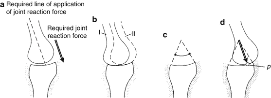

Fig. 18.3
(a) Assume that a joint must produce the joint reaction force shown in the figure, while the joint position remains constant. (b) For the required angle, the joint can assume any stable position between locations I and II. (c) The range of orientation of the joint reaction force that can be produced by joint contact alone is shown. (d) The joint will seek the contact position where the perpendicular to the contacting surfaces at the contact point (P) is in the required direction [Taken from 2]
The occurrence of an intra-articular fracture disrupts the curvature of the joint, creating instability at the fracture site. The total arc of motion over which a joint reaction force can be maintained is not altered by the fracture; however, if the joint reaction force is required to move across the fracture site during a functional motion, the joint surfaces will undergo a sudden motion as the contact surfaces jump from one curvature to the other (Fig. 18.4). Such a small change in the joint surface associated with a surface discontinuity produces an unstable joint, which can significantly alter contact stresses [20]. Thus, in the intra-articular fracture model of Furman et al. [18], the subsequent alterations in cartilage may result as much from alterations in joint stability after the fracture as from the mechanical damage that accompanied the original blunt trauma.
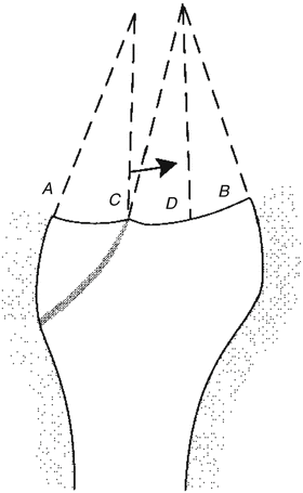

Fig. 18.4
A joint has sustained an intra-articular fracture at point C, causing a discontinuity in the joint surface. The range of orientation of the joint reaction force is bounded by lines A and B. If the joint contact at position C is altered slightly, a large motion of the contacting surface from C to D will occur. The orientation at position D is only slightly different from the orientation at position C [Taken from 2]
Forces created by tensioning of the passive ligaments that connect the bones across the joint also serve to stabilize the joint. For example, during normal knee flexion, functional loads are often required that cannot be generated by the joint reaction force alone, even as the femur translates anteriorly (Fig. 18.5). But as that translation occurs, the posterior cruciate ligament is stretched, thereby creating tension within the ligament. This tensile force provides the additional joint reaction force to maintain joint stability. Depending on where the joint is in its range of motion, the ligament may be loaded or lax. For the contact point to move enough along the joint curvature to create joint compression force, the ligament must allow relative joint motion without producing tension. Thus, ligaments possess a neutral zone, in which the joint can find a stable position based upon joint curvature and the required direction of the joint reaction force. If an equilibrium position does not lie within this zone, additional joint translation induces ligament tension that contributes directly to joint stability.
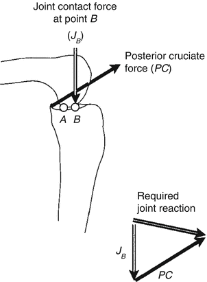

Fig. 18.5
At the contact position shown (point A), the joint contact force cannot provide the required joint reaction. When the femur moves to contact at point B, the posterior cruciate ligament will stretch and pull anteriorly and proximally on the tibia. When these two forces (JB and PC) are added, they produce the required joint reaction force [Taken from 2]
Ligament injuries impact the mechanical burden placed on the joint in important ways. The velocity and distances through which the articular surfaces move relative to one another in the presence of a stretched or torn ligament increase dramatically. For example, a torn anterior cruciate ligament (ACL) in the knee can produce a threefold increase in anterior translation of the tibia relative to the femur [21]. Similarly, a tear in the meniscus also detracts from its stabilizing function, not only allowing larger sliding distances (and hence larger surface velocities) between the tibial and femoral surfaces but also markedly increasing the contact stresses in the underlying cartilage [19].
Muscle forces actively provide joint motion, but they also provide a stabilizing effect by combining two common features of a joint. The first is that the joint must undergo relative motion to change the point of application and hence the direction of the joint contact force. The second is that such small changes in relative position of the joint surfaces provide meaningful changes in orientation and moment arm of the muscle force. If necessary, additional stability can be achieved through abnormal co-contraction of muscles that span opposite sides of the joint. For example, with an ACL injury, co-contraction of the quads and hamstrings across the knee provides additional joint reaction force to help stabilize the joint [22]. Of course, the disadvantage of this additional mechanism is that it creates increased burden on the cartilage and underlying bone because the additional co-contraction force adds to the magnitude of the joint reaction force across the joint surfaces.
Lessons from Total Joint Arthroplasty
The role of kinematics in creating damaging conditions to joint surfaces has been the focus of efforts to improve the wear performance of bearing surfaces in total joint arthroplasty for more than 40 years. Central to those efforts has been an understanding of the wear mechanisms and the mechanical and material conditions that control them. For example, polyethylene wear is dominated by abrasive wear in which the harder opposing metallic surface cuts through the surface of the softer polyethylene, and fatigue wear occurs as a result of the formation and growth of cracks in and below the polyethylene-bearing surface [3, 23]. The amount of abrasive wear is directly proportional to the product of the load across the contacting surfaces and the distance or velocity that the surfaces slide under load. Increased load or large, rapid translations make the polyethylene surface more susceptible to wear. Applying the same principle to articular cartilage, any situation that increases the combination of load times sliding distance or velocity could increase abrasive damage to the cartilage surface.
Fatigue wear is exacerbated in nonconforming metal-on-polyethylene joint replacements where the local stresses are higher due to smaller polyethylene contact areas compared to a more conforming joint [3, 23]. The stress distribution is complex as the contact region moves across the surfaces (Fig. 18.6), with several types of deformation occurring in the polyethylene. Under the contact region, the polyethylene is compressed perpendicular to the surface with the greatest compressive stress occurring at the surface. But because the surrounding material below the surface constrains the compressed material from spreading tangentially, compressive stresses are also created parallel to the surface, the result being a state of hydrostatic compression. At the edge of the contact area, however, the polyethylene is stretched tangent to the surface, resulting in tensile stresses. Finally, the material is also distorted under the contact area, with shear stresses that vary throughout the region and, for nonconforming surfaces, can be greatest below the surface of the polyethylene.
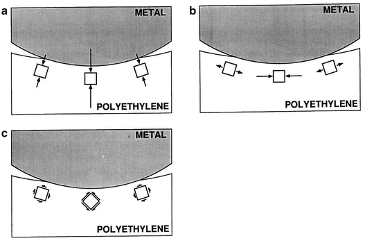

Fig. 18.6
When the metallic femoral component indents the polyethylene, complex stress distributions result, including (a) compressive contact stress perpendicular to the surface, (b) compressive and tensile stresses tangent to the surface, and (c) shear stresses
Can these relationships between mechanisms of abrasive and fatigue wear and joint loads in polyethylene joint replacements help explain the role of biomechanics in a normal joint experiencing the onset and progression of PTA? Recent evidence suggests that they can. For example, in a recent experimental study, Tochigi and colleagues [24] used a rabbit model, in which they subjected animals to either complete or partial ACL transaction as a means of altering joint stability (and, hence, sliding distance and velocity). Joint stability was measured in vivo using an anterior drawer test, from which anterior drawer stiffness and neutral zone length were reported; a lower stiffness and a larger neutral zone were indicative of a more unstable joint. After both 8 and 16 weeks, cartilage degeneration as determined histologically increased with the degree of instability (Fig. 18.7).
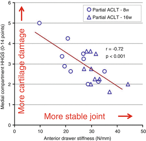

Fig. 18.7


In a rabbit model of partial ACL transection to effect variations in joint stability, the less stable the joint, the greater was the subsequent degree of cartilage degeneration as measured by a histological histochemical grading scale (HHGS) [Adapted from 25]
Stay updated, free articles. Join our Telegram channel

Full access? Get Clinical Tree


