Fig. 15.1
Template Design. Ferrari et al. proposed a multiple low contact points single level template design
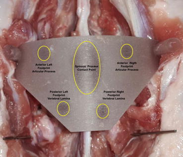
Fig. 15.2
Template Top View (ex-vivo study). There are 2 support points at the level of the articular processes (“anterior shafts”), 2 support points at the level of the vertebral laminae (“posterior shafts”) and a a fitting area located on the sides of the spinous processes (‘central shaft’) that allows the simplification of the template alignment and that facilitates the template correct positioning
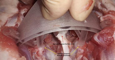
Fig. 15.3
Anterior Support Points on the Articular Processes [ex vivo study]. The presence of multiple contact points (4 or more) reduces the possibility to have a false-stable template positions; the template is well-placed only when all the fitting areas are in contact with the bone surface. In the case of the remaining tissue under the foot of a tripod, this can seem well-positioned because the other two feet are in contact with the bone
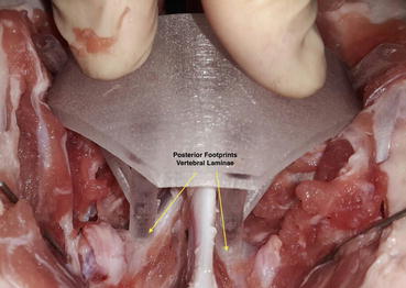
Fig. 15.4
Posterior Support Points on the vertebral laminae [ex vivo study]. The presence of multiple contact points (4 or more) reduces the possibility to have a false-stable template positions; the template is well-placed only when all the fitting areas are in contact with the bone surface
Similar results have been reported by Tomnic et al. in 2014 with the use of multiple contact points design template in the thoracic spine (cadaveric study) [26]. The templates were specially designed to fit and lock on the lamina during the procedure anchoring at three sites – on the lamina at the base of the superior articular process on both sides and at the tip of the spinous process. The templates have a special metallic drill sleeve with inner hole corresponding to the drill bit diameter. These metallic sleeves also prevent formation of debris from the template itself during drilling. The CT Analysis showed that 13 out of 14 (92,9 %) screws were inside of pedicle trajectories without violation of pedicle wall with the tip inside of the vertebral body (Fig. 15.5). One screw violated medial pedicle wall in an “in-out-in” fashion.
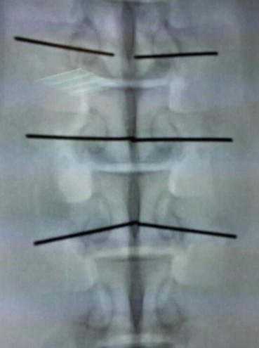
Fig. 15.5
The Template has been tested on an ex vivo animal test (porcine spine). The Postoperative Fluoroscopic Evaluation showed the correct a Kirschner wires alignment. The postoperative CT evaluation (performed after each test session) showed an error less than 1 mm in 93 % of the cases and between 1–2 mm in 7 % of the cases
Full Contact Template Design
To overcome the problems related to the template instability Sheng Lu et al. in 2009, proposed the use of a full contact design [18]. The template surface was created as the inverse of the vertebral posterior surface, thus potentially enabling a near-perfect fit (lock and key solution). This design had been tested on cadaver (6 lumbar spines) and on 6 patients with lumbar spinal pathology. 58 screws were inserted (36 in cadavers, 22 in patients) and no pedicle perforation was observed by postoperative CT scan. In another study published in 2012 the authors evaluate the accuracy of pedicle screws placement with the templates in a group of 16 patients with a thoracic scoliosis [19]. Of the 168 screws implanted 157 screws were considered intrapedicular, while 11 screws were considered to have a 0–2 mm breach without any pedicle screw brech more than 2 mm. As stressed by the authors to avoid screws misplacement a meticulous preparation of the bone surface was essential, including thorough removal of the attached muscle and fat tissue without damage to the bony surface structure.
The solution proposed by Sheng Lu [18] for the lumbar spine has been used by Ma et al. 2012 in the thoracic spine [22]. Twenty thoracic cadaver specimens were randomly divided into two groups the template group and the free-hand group. 480 pedicle screws were placed (240 screws for each group). In the template group, 224 screws were fully contained in the pedicles (Grade 0) and 16 screws exhibited pedicle wall violation (all of which were classified as Grade 1). In the free-hand group, 156 screws were fully contained in the pedicles (Grade 0) and 84 exhibited pedicle wall violation. Screw misplacement in the template group were related mainly to an inadequate soft tissue preparation that led to a template wrong positioning. Accuracy of screw placement in the two groups was 93.4 % and 65 %, respectively. In the free-hand group, the accuracy of screw placement in the first five and the last five cadaver specimens was 55 and 75 %, respectively, whereas in the navigational template group the values were 91.6 % and 95 %, respectively (P [0.05]). Thus, there was an evident learning curve in the free-hand group that was not detected in the navigational template group.
To avoid the errors related to a template wrong positioning with the use of a full contact design Sugawara et al. in 2013 proposed to use three different templates for each level: a location template with 3-mm-diameter holes was made to mark the screw entry points on the lamina, a drill guide template to control the screw trajectory before screw insertion and a screw guide template to control screw insertion [29]. The authors tested this solution on study in 10 patients with thoracic or cervicothoracic spinal pathological entities. A total of 58 thoracic pedicle screws were inserted. Postoperative CT scans confirmed that no screws violated the cortex of the pedicles, and the mean deviation of the actual screw trajectory from the planned screw trajectory on the coronal plane at the midpoint of the pedicle was 0.87 ± 0.34 mm. Also with the use of three templates for each level the authors point out the importance of an accurate preparation of the soft tissues to ensure the perfect fit and lock of the templates on bone.
Discussion
Pedicle screw placement is usually performed using a free- hand technique, with high risk of screws malpositioning especially in cervical or thoracic spine or in presence of spine deformity. Robotic and image-guided solutions have been proposed to perform safer interventions, but the application is expensive and their use requires a learning curve that can be too long, particularly for small hospitals that perform a limited number of spine stabilization yearly [5–8]. Furthermore, surgical navigators require a cumbersome localizer in the surgical setting and a registration procedure to correctly position and orientation the drill following the navigator screen, and keep it stable during the drilling phase, a task which is not always simple to perform.
A different, less expensive, and less complex image-guided approach involves the use of patient’s specific templates. An ideal Patient’s Specific Template should be: stable in a unique position, easy to use, easy to place (with a high reproducibility), less invasive and very accurate. As emerged from the literature review each template should be designed to fit on one vertebra; all the multilevel templates manufactured until now, had low accuracy level due to the changes in the relationship between each vertebral bodies from the CT acquisition to the surgical table. The accuracy of placement mainly depends on the template design, the fitness between template and vertebra, and the surgical procedure. For the template design is important a right balance between template stability and ergonomics in relation to the soft tissues. Templates that are designed as the inverse of the bone surface (full contact design) allow to obtain an high stability on bone (lock and knee mechanism) with an high level of accuracy at the clinical test but this kind of design needs a precise decortication of a large area of bone from soft tissues, which takes additional surgical time and increases the invasiveness of the procedure [16–22]. An inappropriate preparation of the soft tissues can result in a high level of error and screws misplacement. Templates that are designed to be fixed in its position by touching small parts of the dorsal elements of the spine in a few spots (e.g., V-shaped knife), had often limited or inappropriate accuracy due to the template instability [13, 24, 27]. As emerged from the study of Berry et al. the use of only three contact points can result in false-stable positions and it does not give to the surgeon the right feel in the use of the template [13].
Recent studies have re-proposed the use of small contact points or fitting areas, which are designed as the complementary likeness of the bone surface, not just a ‘V shape’ [25, 26]. This kind of design allows one to obtain template stability without increasing intervention invasiveness. It is important that the template design is optimized taking in account mechanical considerations to guarantee template stability, simple positioning and minimal intervention invasiveness. The presence of multiple contact points (4 or more) reduces the possibility to have a false-stable template positions; the template is well-placed only when all the fitting areas are in contact with the bone surface. In the case of the remaining tissue under the foot of a tripod, this can seem well-positioned because the other 2 feet are in contact with the bone. Nevertheless, in the case of multiple contact points, another foot would be far above the bone surface revealing a template false-stable position [25]. Regards the choice of the supporting points the majority of proposed designs using the spinous process as the main reference [13, 16–22, 24–27]; in our experience the spinous process is to be used as a reference point for the orientation and positioning of the template, but not as a support point for the presence of posterior ligaments that cover the bone [25]. The other supporting points can be fixed on the vertebral laminae, articular processes or transverse processes without great differences in terms of the template stability (the use of transverse processes requires a larger bone exposure), to increase the template stability it is important that the supporting points cover different planes to construct a stability area in which the center of gravity of the template must fall. The orientation of the supporting points has to choose to maximize template stability. For this reason, no tangential force must be imposed on the fitting areas to avoid the need for friction between the bone and the template to fix it and avoid sliding. Furthermore, the forces must be aligned with the shaft axes to prevent deformation, and consequently the deformation of the entire template. For these reasons the shafts should be positioned orthogonal to the bone surface [25].
Related posts:
 Virtual Preoperative Planning
 Computational Image-Guided Technologies in Cranio-Maxillofacial Soft Tissue Planning and Simulation
 Virtual Cranio-Maxillofacial Surgery Planning with Stereo Graphics and Haptics
 Spinal Loading System: A Novel Technique for Assessing Spinal Flexibility in Adolescent Idiopathic Scoliosis
 Navigation in Spinal Surgery
 3D Projection-Based Navigation
Stay updated, free articles. Join our Telegram channel

Full access? Get Clinical Tree


