The evolution of occipitocervical fixation and new rigid universal screw-rod construct technology has allowed secure anchorage at each level of the occipitocervical junction with the elimination of rigid external orthoses. Rigid occipitocervical instrumentation constructs have achieved higher fusion rates and less postoperative immobilization-associated complications. Outcomes have improved compared with former nonrigid instrumentation techniques; however, with advances of rigid occipitocervical stabilization capability have come new challenges, risks, and operative techniques. A thorough understanding of the relevant cervical bony and soft tissue anatomy is essential for safe implantation and a successful outcome.
- 1.
Preoperative imaging studies must be thoroughly reviewed for vertebral artery aberrant paths or inadequate bone stock for safe screw placement.
- 2.
Meticulous attention to dissection is required to avoid excessive C1-2 venous sinusoid bleeding and to appreciate bony anatomic landmarks for safe instrumentation.
- 3.
Planning and thorough familiarity with upper cervical spine anatomy are critical.
- 4.
Versatile fixation techniques should be familiar and applied if bony anatomy precludes use of C2 pedicle screw instrumentation.
- 5.
Appropriate patient positioning and visualization with intraoperative fluoroscopy are needed to facilitate both exposure and instrumentation.
Occipitocervical fusion may be indicated for multiple disease processes that render the craniocervical junction unstable. The causes may include trauma, rheumatoid arthritis, infection, tumor, congenital deformity, and degenerative processes. This junctional area between the mobile cervical spne and the rigid cranium offers fixation challenges and has a high incidence of significant and devastating spinal cord injury. Historically, stabilization of this junction dates back to 1927 when Foerster used a fibular strut graft construct. Since then, other nonrigid methods of stabilization have been trialed, including wire fixation, pin fixation, hook constructs, and many others with onlay bone graft and halo immobilization. However, these options required cumbersome, prolonged, postoperative external immobilization, including a halo vest or Minerva jacket to improve fusion rates and sometimes extended bed rest with traction. In an attempt to improve fusion rates and clinical outcomes and reduce the use of external immobilization, rigid internal fixation evolved.
In the early 1990s occipitocervical plate and screw fixation was developed, which provided immediate rigidity to the spine, thus eliminating postoperative halo vest immobilization. In addition, it was not necessary to pass a sublaminar wire, which was a risky aspect of the Luque fixation technique. Despite these advantages, plate and screw constructs did have limitations. These included a fixed hole-to-hole distance that may not match patient anatomy, preventing optimal screw placement; plate bulk, limiting space for graft material; and an inability to compress or distract across interspaces. Occipital plate fixation also limited the ability to place occipital screws along the midline, the thickest and strongest bone area in the occiput.
In the mid-1990s, with the advent of rod-screw instrumentation, the limitations of plates were eliminated. The screws provided excellent fixation, and the use of rods allowed unlimited screw placement. There was greater space for bone grafting, and the ability to compress or distract became available.
Occipital fixation has also dramatically improved because of the use of rigid fixation with contoured rod-screw instrumentation. Bicortical placement in the thickest and strongest bone along the occipital midline offers a biomechanical advantage and promotes stability and rigidity and thereby increases fusion rates. A technique using offset connectors and rods has been described that optimizes the ability to place 6 occipital screws in the parasagittal plane along the midline. Several studies have also compared the stability of various occipitocervical constructs and demonstrated that rigid occipitocervical fixation is superior to wiring or other nonrigid techniques. A recent clinical comparison of short-term outcomes confirmed a statistically significant lower rate of complications and superior clinical outcomes with rigid versus nonrigid occipitocervical fusion constructs.
With the development of universal screw-rod instrumentation, techniques for stable cervical screw anchors proliferated. C1 lateral mass screw fixation, C2 pedicle screw fixation, C2 translaminar screw fixation, C1-C2 transarticular screws, and subaxial lateral mass screws can now all attach either directly or through offset connectors to a longitudinal rod. These common cervical anchors provide rigid stability and have been found to be biomechanically superior to previous nonrigid fusion constructs. Universal screw-rod internal instrumentation has improved fusion rates and allowed immediate stability. The evolution of this instrumentation technology has resulted in the best opportunity to improve clinical outcomes and mitigate complications associated with nonrigid constructs.
Surgical indications
The occipitocervical junction is susceptible to a wide variety of pathologic conditions that predispose it to instability. Any patient with instability, as a result of trauma, rheumatoid arthritis, infection, and congenital or tumor causes, experiencing a neurologic deficit requires arthrodesis. All cases with traumatic dislocation require primary surgical stabilization with a posterior occiput to cervical fusion. Other causes include incompetent occipitocervical ligamentous structures or associated vertical migration of the odontoid with rheumatoid arthritis, although less common with the advent of antirheumatic medications.
Anatomy
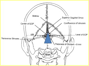
Stabilization of the occipitocervical junction requires comprehensive knowledge of the anatomy. For safe placement of occipital screws, anatomic knowledge of regional occipital bony thickness and location of venous sinuses is essential. Anatomic studies of the occiput have demonstrated that the external occipital protuberance is the thickest in the midline and decreases laterally to inferiorly. Screw fixation is preferred below the level of the superior nuchal line to avoid a transverse sinus injury and along the dense midline ridge below the external occipital protruberance. The superior sagittal sinus runs from the confluence of both transverse sinuses superiorly along the occipital midline ( Fig. 1 ). The quality of this midline bone stock is optimal and is the ideal occiput screw fixation point desired.
For atlantoaxial instrumentation and fixation, multiple fixation methods may be used, including transarticular screws, C1 lateral mass screws, or C2 pedicle, pars, or translaminar screws. Transarticular screws require a drill trajectory that starts at the C7-T1 region. Thus, excessive kyphosis precludes the ability to obtain the approach angle. Likely, the presence of an irreducible C1-C2 subluxation, deficient C2 bony pars, or aberrant medialized vertebral artery excludes this option. These anatomic variations must be evaluated as part of the preoperative plan.
The atlas is a large ring composed of 2 large lateral masses connected by an anterior and posterior arch. The lateral masses are wedge shaped and are congruent with the occipital condyles. The posterior arch contains a groove superiorly in which the vertebral artery lies. The C1 lateral mass lies anterior to the C1 posterior arch and must be carefully exposed to avoid venous plexus bleeding between C1 and C2. Subperiosteal reflection along the C1 posterior arch lateral undersurface facilitates lateral mass exposure without bleeding ( Fig. 2 ). Once exposure of the posterior aspect of the C1 lateral mass is achieved, the C2 nerve with its venous sinusoid can be retracted caudally to expose the joint. Width of the C1 lateral mass should be established to avoid medial or lateral screw placement and potential spinal cord or vertebral artery injury, respectively. After perimeter margins are delineated, C1 lateral mass screw may be placed as popularized by Harms and Melcher.
The axis is unique with the dens projecting cranially from the body to articulate with the anterior arch of the atlas and transverse ligament. Large lateral masses project laterally from the body. The lateral masses connect to the posterior elements through pedicles and a narrow bony isthmus or pars interarticularis. The C2 spinous process is bifid and serves as an attachment of the nuchal ligaments and cranial rotator muscles. The course of the vertebral arteries through the axis is variable and must be understood to minimize injury during surgery ( Fig. 3 ). There are several options for axis screw fixation dependent on patient anatomy and surgeon preference. C2 pedicles should be evaluated on computed tomographic images for bony deficiency or a high-riding vertebral artery that would exclude pedicle screw fixation as a viable option. It is mandatory to differentiate between a screw placed into the C2 pars interarticularis and one placed into the C2 pedicle. These screw sites are not identical and possess distinct challenges of insertion and different potential complications.
The confusion between the positions of these screw types lies in the unique anatomy of the C2 vertebra. The pars interarticularis is the region of bone between the superior and inferior articular processes. The pedicle is the region of bone that connects the posterior elements to the vertebral body. Because the superior articular process of C2 is extremely far anterior, the pars interarticularis is very large. This anterior position of the superior articular process also creates a very narrow and short window for connection to the C2 body, the pedicle.
The C2 pars interarticularis screw is in the exact position as a transarticular C1-C2 screw, except it stops short of the joint. The entry point is the same (approximately 3 mm superior and 3 mm lateral to the medial aspect of the C2-3 facet joint) ( Fig. 4 ). As with transarticular C1-2 screws, the greatest risk associated with placement of the C2 pars screw is injury to the vertebral artery. Although this screw is a shorter version of the transarticular screw, it follows the same trajectory stopping short of the C1-2 joint.
The C2 pedicle screw follows the path of the pedicle into the vertebral body. For a screw to be inserted into the C2 vertebral body from the posterior elements, it by definition has to pass through the pedicle. The entry point is significantly cephalad to the entrance for the pars screw and slightly lateral (see Fig. 4 ). The medial angulation is significantly more than that of the pars screw, approximately 20° to 30°, although the pars screw is placed almost straight ahead. This cephalad starting point and medial angulation makes the pedicle screw less likely to injure the vertebral artery. The artery runs from medial to lateral in front of the C2-3 facet joint. The pedicle screw starts cephalad from the artery compared with the pars screw where the artery may be medial or just anterior to the starting point (see Fig. 4 ). In addition, the pars screw does not have a steep medial trajectory and is closer to the artery as it moves toward the superior articular process. The C2 pedicle screw cephalad trajectory is also not as steep, approximately 30° compared with more than 45° with the pars screw, and can usually be placed through the incision. The pars and transarticular screws need to have a very steep cephalad trajectory to keep away from the vertebral artery, which usually requires placement through percutaneous stab incisions at the cervicothoracic junction.
Anatomy
Stabilization of the occipitocervical junction requires comprehensive knowledge of the anatomy. For safe placement of occipital screws, anatomic knowledge of regional occipital bony thickness and location of venous sinuses is essential. Anatomic studies of the occiput have demonstrated that the external occipital protuberance is the thickest in the midline and decreases laterally to inferiorly. Screw fixation is preferred below the level of the superior nuchal line to avoid a transverse sinus injury and along the dense midline ridge below the external occipital protruberance. The superior sagittal sinus runs from the confluence of both transverse sinuses superiorly along the occipital midline ( Fig. 1 ). The quality of this midline bone stock is optimal and is the ideal occiput screw fixation point desired.
Related posts:
 Management of Adjacent Segment Disease After Cervical Spinal Fusion
Esophageal and Vertebral Artery Injuries During Complex Cervical Spine Surgery—Avoidance and Management
Management of Cervical Spine Trauma: Can a Prognostic Classification of Injury Determine Clinical Outcomes?
Minimally Invasive Approaches to the Cervical Spine
Esophageal and Vertebral Artery Injuries During Complex Cervical Spine Surgery—Avoidance and Management
Management of Adjacent Segment Disease After Cervical Spinal Fusion
Management of Adjacent Segment Disease After Cervical Spinal Fusion
Esophageal and Vertebral Artery Injuries During Complex Cervical Spine Surgery—Avoidance and Management
Management of Cervical Spine Trauma: Can a Prognostic Classification of Injury Determine Clinical Outcomes?
Minimally Invasive Approaches to the Cervical Spine
Esophageal and Vertebral Artery Injuries During Complex Cervical Spine Surgery—Avoidance and Management
Management of Adjacent Segment Disease After Cervical Spinal Fusion
Stay updated, free articles. Join our Telegram channel

Full access? Get Clinical Tree


