Metal-on-Metal Articulations
Tim Band
The origins for the metal used for metal-on-metal articulations can be traced back to 1938 when Phillip Wiles implanted a stainless steel on stainless steel bearing; however, it was in 1939 when Smith-Peterson used a hip cup prosthesis (mold arthroplasty) manufactured from cobalt chrome molybdenum (CoCr) alloy for resurfacing the proximal femoral bone. This prosthesis was a “hollow shell” which was placed over the proximal femur and articulated against the natural acetabulum with such a thin component cross-sectional thickness that it truly was a “resurfacing” of the bone rather than a resection.
This early implantation of CoCr provides the basis for the long-term clinical biocompatibility of this material and provided an intrinsic design principle for hip resurfacing, which is discussed later in this chapter.
For the first recorded use of CoCr alloy in metal-on-metal hip arthroplasty it is McKee who needs acknowledgement when he produced a metal acetabular cup which articulated with the metal Thompson prosthesis previously used as a hemiarthroplasty. The McKee device was a cemented system on both the femoral stem and acetabular cup with a diamond cross-sectioned stem and sputnik-featured cup (Fig. 20.1).
Shortly after McKee, using the same material, Peter Ring produced his cementless metal-on-metal prosthesis which had a flat stem similar to the Austin-Moore design but with a mating acetabular device with a long-threaded stem which was inserted into the ilium (Fig. 20.2).
Other designs were introduced and included the Huggler, Muller, and Stanmore devices and these prostheses were produced using the lost wax investment casting process and while device material specifications were not formerly recorded, extensive forensic analysis confirmed that they were machined and supplied in the “as cast” microstructural condition.
The “as cast” microstructure can be described in metallurgical terms, which is important to consider as the alloy evolved over time in its use as an orthopedic device material and will be discussed later in this chapter. The investment casting process involves the melting of specific volumes of the constituent elements of the alloy. For CoCr alloy, which is now specified today in International Standards ASTM F75 and ISO 5832 (IV), the constituent elements are cobalt, chromium, molybdenum, nickel, iron, manganese, silicon, and carbon and their respective composition percentages in the alloy are shown in Table 20.1.
Once these elements have been precisely weighed according to their content in the specification the mixture can be heated to temperatures above the melting temperature of the metal elements, typically >1,550°C, to melt the elements to form a homogeneous molten liquid. Melting usually takes place in an induction furnace in a vacuum, or with an inert gaseous shroud, to protect the molten metal from oxidation of the reactive elements. Such oxidation can result in impurities in the alloy which can manifest as “defects” or
“nonmetallic inclusions” in the final cast product which in turn can result in cosmetic, appearance defects on product surfaces (particularly highly polished) or more significantly as discontinuations in the alloy microstructure, leading to reduced structural strength of the alloy. This is significantly more important in long-stemmed components which are exposed to fatigue and torsional loading in vivo and where good fatigue strength properties are required.
“nonmetallic inclusions” in the final cast product which in turn can result in cosmetic, appearance defects on product surfaces (particularly highly polished) or more significantly as discontinuations in the alloy microstructure, leading to reduced structural strength of the alloy. This is significantly more important in long-stemmed components which are exposed to fatigue and torsional loading in vivo and where good fatigue strength properties are required.
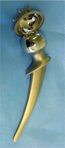 Figure 20.1. McKee–Farrar metal-on-metal total hip prosthesis. |
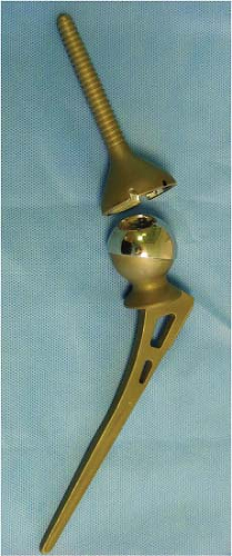 Figure 20.2. Ring metal-on-metal total hip prosthesis. |
Once the “bulk” alloy production has taken place, which can be typically 1,000 kgs or more, the molten alloy is poured out of the furnace into individual molds which produce the resulting billet shape. These billets can be cylindrical or rectangular in shape and are identified with a traceability lot code which is traceable to the chemical analysis of the bulk material, or master melt. The microstructure or structural integrity of these billets is not critical as further melting is required to form the final orthopedic device (Fig. 20.3).
To produce the final shape of the orthopedic device it is necessary to produce a mold which contains cavities of the implant shape for the liquid alloy to be poured into. These cavities are formed by producing a number of wax facsimiles of the implant and then assembling them onto a wax runner and pour cup system often called a “tree.”
Methods of producing the wax facsimiles are varied and complicated but usually involve the machining of a cavity, slightly larger than the implant size to allow for subsequent process contractions, in Aluminum blocks which are split across the junction of surfaces of a device or about a central axis of symmetry with an injection port to the outside of the block (Fig. 20.4).
Table 20.1 ISO 5832 (IV) (A) and ASTM F75 (B) Chemical Composition | |||||||||||||||||||||||||||||||||||||||||||||||||||||||||||||||||||||||||||||||||||||||
|---|---|---|---|---|---|---|---|---|---|---|---|---|---|---|---|---|---|---|---|---|---|---|---|---|---|---|---|---|---|---|---|---|---|---|---|---|---|---|---|---|---|---|---|---|---|---|---|---|---|---|---|---|---|---|---|---|---|---|---|---|---|---|---|---|---|---|---|---|---|---|---|---|---|---|---|---|---|---|---|---|---|---|---|---|---|---|---|
| |||||||||||||||||||||||||||||||||||||||||||||||||||||||||||||||||||||||||||||||||||||||
This injection port and split cavity permits the injection of liquid wax to be injected under pressure into the tool cavity. Once injected, the tool can be opened to reveal the wax component, which is the facsimile of the final implant shape. The oversize condition is to provide for subsequent contractions which occur later in the manufacturing process as the alloy undergoes liquid to solid state transformation. Once the wax patterns are produced they are attached to the wax runners via a “gate” which is positioned in a noncritical area on the product (Fig. 20.5), to allow its final removal after casting, and after considering its influence on the final microstructure of the implant (i.e., the gate is normally the last point of the implant to solidify after casting and can have a larger grain size than other thinner sections of the implant which solidify earlier and can influence strength).
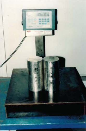 Figure 20.3. CoCr alloy billets in surface ground cylindrical form. |
The final wax tree, with its pouring cup, is progressively coated in a ceramic shell coat to produce a final ceramic layer, or shell, around the wax tree of approximately 5 mm in thickness. This coating is achieved by progressive immersions in ceramic fluids and coatings of ceramic stuccos (Fig. 20.6).
Once the shell is complete, following a few days to allow drying of the shell coat between each dipping and coating process, in a rapid transfer time to an autoclave it is subjected to temperatures around 150° to 180°C to “dewax” the shell. This is where the wax is removed and is where the “lost wax” process name originated. The transfer time is rapid for the shell containing wax to move to the heating chamber to avoid splitting the shell through the greater relative expansion of the wax inside the shell. The wax melts from the inside of the ceramic shell, leaving a mold in the correct shape and volume of the wax patterns and runners. The first, or primary, face coat of the investment process provides a smooth surface for the molten metal to solidify against after pouring into the shell as shown in Figure 20.7.
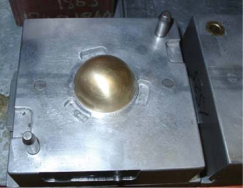 Figure 20.4. View inside a wax pattern tool cavity split to reveal brass insert used to form concave surface of an acetabular cup. |
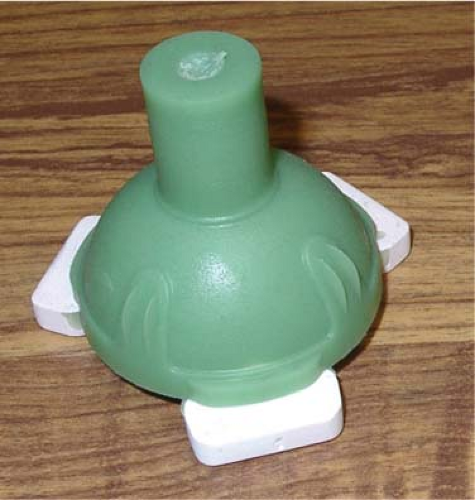 Figure 20.5. A wax pattern of an acetabular cup showing the feed gate on the convex surface and three ceramic core prints. |
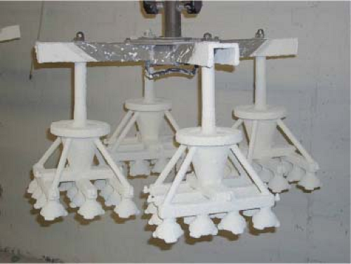 Figure 20.6. Wax assemblies supported by a robotic arm from shell dipping. |
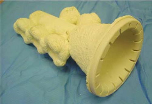 Figure 20.7. Ceramic shell after dewaxing and flash firing. |
After the shell has been dewaxed it is heated in a preheat furnace at temperatures around 1,000° to 1,100°C where it goes through a phase change, from its “green” state, strengthening the ceramic structure. Billets of CoCr alloy produced in the bulk material process are heated and melted in a small induction furnace (weighs around 10 to 20 kgs) at temperatures above 1,550°C, again in a protective environment, and subsequently the liquid metal is poured into the hollow shell (Fig. 20.8).
Once the molten metal is poured into the ceramic shell the alloy starts to solidify at the metal–shell surface interface. Cooling starts with chill crystals, or grains, forming over the entire surface of the cast metal where it meets the cooler surface of the shell. The chill layer is approximately 100 microns (μm) thick and subsequent grains have an equiaxed morphology and are of a larger size as shown in Figure 20.9.
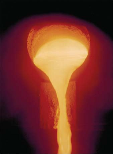 Figure 20.8. Molten alloy being poured from a preformed ceramic melting crucible. |
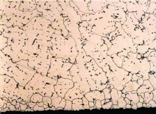 Figure 20.9. As cast CoCr microstructure showing chill crystal layer on casting surface and larger grain size. |
Solidification of the casting starts from the outside surfaces with the thermal gradient increasing inside the casting with thicker sections of the component remaining warmer for longer, which allows liquid metal to continue flowing into the solidifying shapes from the larger sections and volume of the runner bars. Once the gate has solidified, no further liquid alloy can feed the casting from the runner bars. When the phase change occurs from liquid to solid, if there has been insufficient “feeding” during solidification then microvoids occur which are known as “porosity” (this is discussed later and shown in Figure 20.18). The porosity can significantly reduce the structural integrity and strength of the alloy, and component, in a similar manner to the nonmetallic inclusions, discussed earlier. Solidification occurs with grains forming and growing in dendritic formations or patterns. The dendritic pattern has been compared to the branches of a Christmas tree where arms form perpendicular orientations to a central axis (Fig. 20.10). These smaller branches have subsequent perpendicular offshoots which eventually meet and cross one another as adjacent dendritic arms form in the alloy.
The final liquid to solidify in the region between the branches of the dendritic arms is rich in chromium, molybdenum, and carbon and upon final solidification this liquid forms precipitate carbides at these dendritic intersections and at the grain boundaries. These are noncontinuous, discrete components known as interdendritic carbides where ionic and covalent bonds exist for metallic carbides of Cr, Mo, and C. As the alloy solidifies in this dendritic pattern, “coring” or segregation occurs as slight variations in chemical composition solidify at marginally different rates. The combination of the cobalt-rich matrix and the precipitate carbide is described as a biphasic microstructure and can be seen in the micrograph shown in Figure 20.11.
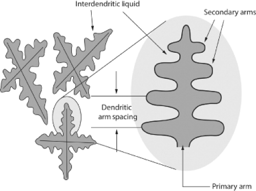 Figure 20.10. Dendrite pattern occurring during solidification of the molten alloy. |
Although there are a number of carbide types which can form in the bulk material, chemical composition and transmission electron microscopy confirms the predominant type of carbide in the CoCr as cast alloy is M23C6. The current maximum content of carbon in CoCrMo alloy is specified as 0.35% as shown in Table 20.1 earlier in the chapter, which prevents the formation of continuous networked grain boundary carbides which can significantly reduce the mechanical properties of the alloy. Early specifications suggest that 0.5% carbon was employed which lead to this risk of carbon saturation and material embrittlement. The image below (Fig. 20.12) shows a typical “as cast” microstructure with interdendritic M23C6 carbides and grain boundary carbides within the micrograph.
It is in this as cast microstructural condition that the alloy has its lower fatigue strength and when used for long, thin section stems such as the Ring prosthesis, contributed to implant fracture. The solution to this process is discussed later; however, it was in this as cast microstructural conditions that the first-generation metal-on-metal bearings were produced. The stability and distribution of the “as cast” block carbides has been scientifically and clinically demonstrated to be significant in providing low wear characteristics to this alloy, allowing it to be used as a metal-on-metal bearing (1,2,3,4,5,6,7,8). Evidence to support the long-term benign clinical use of this material continues to become available with hosts of the first-generation metal-on-metal bearings enjoying continued success after more than 40 years (Fig. 20.13).
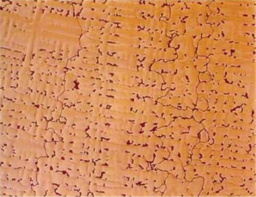 Figure 20.11. Micrograph of as cast CoCr showing precipitate “block” carbides, segregation (coring), and grain boundaries. |
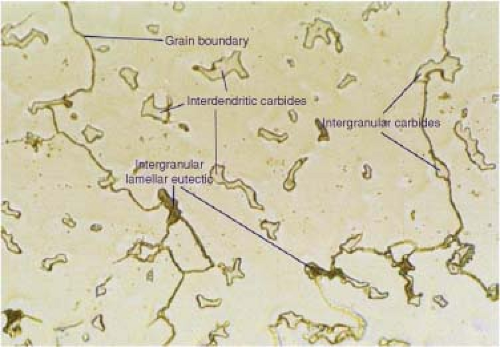 Figure 20.12. Micrograph of as cast CoCr showing biphasic structure of carbide and matrix. |
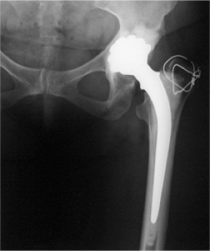 Figure 20.13. Forty-year radiograph of Stanmore metal-on-metal total hip prosthesis implanted in 1970. |
Related posts:


Stay updated, free articles. Join our Telegram channel

Full access? Get Clinical Tree


