Magnetic Resonance Imaging of the Hip
Alissa J. Burge
Stephanie L. Gold
Brett M. Lurie
Hollis G. Potter
Magnetic resonance imaging (MRI) imaging of the hip may be inherently more challenging than other joints due to a variety of anatomic factors, including the location of the joint relative to magnetic isocenter, the curvilinear contour of the articular surfaces, and the relatively thin articular cartilage. With careful attention to imaging parameters and the utilization of optimal technique, however, accurate and reproducible imaging may be obtained in a routine clinical setting, without the need for intra-articular contrast. Given the increasing numbers of hip arthroscopies being performed recently, MR imaging provides an important noninvasive means for accurate evaluation of the hip joint in both preoperative and postoperative settings.
Principles of MRI
Magnetic resonance imaging is based on the ability of spinning atomic species possessing an odd number of nucleons to induce a local magnetic field. Due to its ubiquitous nature, 1H, which contains a single proton, is the isotope upon which the vast majority of clinical MR imaging is based. Upon application of an external magnetic field, Bo, the normally randomly oriented hydrogen nuclei align their spins parallel to the long axis of the field, yielding a net magnetic vector, Mz, along the longitudinal axis of the field. In addition to spinning, these nuclei are simultaneously precessing about the axis of the external magnetic field with a motion much like the wobbling of a top, at a specific precessional frequency as determined by the field strength of Bo. Because this precessional motion is not synchronized among individual nuclei, no net magnetization vector is generated in the transverse plane. By application of a brief radiofrequency pulse oriented at 90 degrees to the longitudinal axis of the main magnetic field, these spinning and precessing nuclei are raised to a higher energy state in which they are simultaneously spinning about their individual axes and precessing in the transverse plane about the axis of the main magnetic field in a synchronized fashion, referred to as the state of being “in phase” with one another. This precessional synchronicity results in generation of a net transverse magnetization vector, Mxy, which, due to the precessional rotation of the nuclei in the transverse plane, allows transmission of the MR signal via induction of magnetic flux within the receiver coil. This flux is essentially an alternating current, which converts to voltage by the resistance of the coil and subsequently undergoes a series of digital manipulations to eventually form an image. Upon termination of the 90-degree RF pulse, the transverse magnetization vector is diminished via two simultaneous but independent processes: recovery of magnetization in the longitudinal axis (spin–lattice, or T1, relaxation) and precessional dephasing in the transverse plane (spin–spin, or T2, decay). These relaxation parameters form the basis of MR tissue contrast, as the relaxation parameters of a particular hydrogen nucleus depend upon its individual biochemical environment, thereby determining its signal characteristics upon images generated by a given pulse sequence.
With deliberate modification of pulse sequence acquisition parameters, different types of soft tissue contrast may be achieved within the generated images, a concept referred to as image weighting. The main acquisition parameters contributing to image weighting are the interval between RF pulses (time to repetition, TR) and the interval from RF pulse to the sampled signal, or echo (time to echo, TE). The pulse sequences most commonly employed in musculoskeletal MRI yield T1-weighted, T2-weighted, and proton density (PD)–weighted images, and are obtained utilizing variable combinations of long and short TRs and TEs. The addition of fat-suppressed, fluid-sensitive images allows sensitive detection of mobile water. Knowledge of the expected signal characteristics and morphology of normal anatomic structures upon differently weighted images is key in image interpretation, allowing differentiation of normal tissue from pathologic conditions, thereby facilitating recognition of pathology.
Imaging the Native Hip
Conventional Imaging Techniques
Magnetic resonance imaging of the hip at clinical field strengths is best performed at 1.5 to 3.0 Tesla (T), utilizing a two-part shoulder coil, small field of view wrap coil, or multiple-channel cardiac coil. A phased-array torso coil, comprising several elements, may be employed to increase signal-to-noise ratio while allowing simultaneous visualization of
both hips. Optimal differential tissue contrast is achieved with moderate echo time fast spin echo (FSE) sequencing at an effective echo time of 34 ms at 1.5T, or 28 ms at 3T (1).
both hips. Optimal differential tissue contrast is achieved with moderate echo time fast spin echo (FSE) sequencing at an effective echo time of 34 ms at 1.5T, or 28 ms at 3T (1).
The hip is routinely imaged in the coronal, sagittal, axial and/or oblique axial planes; while certain structures are best evaluated in a specific imaging plane, each plane provides valuable information, particularly given the complex morphology of the hip joint. Structures which are well evaluated in the coronal plane include the superior labrum, the transverse extent of the superior femoral head and acetabular dome articular cartilage, the hip abductors and short external rotators, the iliofemoral ligament, and the hamstring origins and adjacent sciatic nerves. The sagittal imaging plane is well suited for evaluation of the anterior labrum, as well as of the anteroposterior extent of the superior femoral head and acetabular dome articular cartilage. Straight axial images provide optimal evaluation of the direct anterior and posterior aspects of the femoral and acetabular wall articular cartilage, as well as allowing excellent evaluation of the sciatic, femoral, and obturator nerve. Oblique axial images are commonly substituted for straight axial images in younger individuals in which there is a suspicion of femoroacetabular impingement (FAI), as this plane provides direct visualization of the anterior femoral head–neck junction, facilitating detection of a cam lesion and aiding in surgical planning for neck debridement. Evaluation of the pelvis and contralateral hip may be achieved efficiently utilizing limited large field of view fluid-sensitive and intermediate FSE sequences in complimentary planes, allowing detection of intrapelvic pathology, evaluation of the extent of fluid collections and edema, and gross visualization of pathology within the contralateral hip (1).
MR arthrography has been advocated as providing more sensitive detection of labral and chondral defects than noncontrast MR imaging techniques. While some authors have reported an advantage in detecting these types of injuries following the intra-articular administration of gadolinium-based contrast, other authors have observed statistically equivalent or superior sensitivity and specificity utilizing noncontrast techniques. The efficacy of one approach versus the other typically depends in large part upon the interpreting radiologist, and therefore, the determination of which technique is optimal in a given situation is often dependent upon the preference of the interpreting radiologist in terms of their comfort level and past experience. The authors advocate high-resolution noncontrast imaging of the hip not only for its ability to provide sensitive detection of chondral and labral lesions, but also for its ability to visualize the synovium and provide sensitive evaluation of chondral signal changes in the absence of focal chondral defects (2,3,4).
MR imaging evaluation of the vascular system may be achieved utilizing both noncontrast and contrast-enhanced techniques. Noncontrast techniques typically employ flow-sensitive gradient-echo acquisitions, and are useful for imaging relatively large-caliber vessels with straight courses and rapid flow. For smaller vessels with slower flow and more complex courses, the administration of gadolinium-based contrast material is typically required. MR angiography is often employed about the hip for preoperative assessment of vascular integrity in the setting of traumatic injury, as well as for evaluation of postoperative complications such as pelvic deep venous thrombosis (5,6,7).
Advanced Imaging Techniques
Quantitative MR imaging techniques allow noninvasive assessment of articular cartilage composition, and may be used as a biomarker for early depletion of specific elements of the chondral matrix. While conventional grayscale images depict changes in chondral signal and morphology, quantitative imaging techniques utilize specific pulse parameters and postprocessing algorithms to allow quantitative calculation of certain relaxation values shown to correlate with chondral proteoglycan content, collagen orientation, and free water content (1).
T2 Mapping
T2 mapping is a quantitative technique allowing direct calculation of the transverse relaxation time constant, T2, on a pixel by pixel basis. Changes in T2-relaxation time have been shown to correlate with collagen orientation and free water content, with relatively short T2-relaxation times typically encountered in the highly ordered deep or radial zone of normally stratified cartilage, and relatively prolonged times observed in the transitional zone, due to its less ordered structure. While the lamina splendens or superficial zone may be seen as a hypointense thin rim of cartilage routinely in the thicker cartilage of the knee joint, it is usually not depicted at clinically relevant field strength in the hip. Alterations in the expected normal stratification pattern of articular cartilage on T2 mapping facilitate recognition of focal areas of early matrix depletion, typically manifesting as areas of T2 prolongation secondary to relative architectural disorder and elevated free water content (8,9).
T1 Rho
Variations in proteoglycan content may be detected utilizing a quantitative technique termed T1 rho, or spin–lattice relaxation in the rotating frame. This sequence utilizes multiple acquisitions per slice at varying spin-lock durations, locking the magnetization vector in the transverse plane to allow detection of low-frequency macromolecular interactions—specifically those involving proteoglycan. Again, expected zonal variations in proteoglycan content exist within normally stratified articular cartilage, and focal deviation from expected normal stratification generally reflects areas of early matrix depletion, with prolongation of T1 rho–relaxation times reflective of areas of proteoglycan loss (10,11,12).
dGEMRIC
Delayed gadolinium-enhanced MRI of cartilage, or dGEMRIC, is an additional quantitative technique utilized as a biomarker for proteoglycan depletion. While T1 rho employs an additional RF pulse to allow proteoglycan detection, dGEMRIC relies on the differential distribution of negatively charged Gd-DTPA within the chondral matrix in an inverse relationship to the fixed charge density provided by negatively charged glycosaminoglycans present within normal proteoglycan. Intravenous administration of Gd-DTPA is followed by a brief course of light exercise, which is then followed by a 45- to 90-minute waiting period to allow distribution of Gd-DTPA within the cartilage (8,13,14).
Sodium MR
Table 25.1 Parameters for Routine Imaging of the Native Hip at 1.5 Tesla | ||||||||||||||||||||||||||||||||||||||||||||||||||||||||||||||||||||||||||||||
|---|---|---|---|---|---|---|---|---|---|---|---|---|---|---|---|---|---|---|---|---|---|---|---|---|---|---|---|---|---|---|---|---|---|---|---|---|---|---|---|---|---|---|---|---|---|---|---|---|---|---|---|---|---|---|---|---|---|---|---|---|---|---|---|---|---|---|---|---|---|---|---|---|---|---|---|---|---|---|
| ||||||||||||||||||||||||||||||||||||||||||||||||||||||||||||||||||||||||||||||
Sodium MR imaging employs a similar concept as dGEMRIC, utilizing the differential distribution of a mobile ionic probe to assess proteoglycan content. In the case of sodium MR, the probe is the positively charged sodium ion, which, because it is a naturally occurring substance, obviates the need for intravenous injection of gadolinium; however, because clinical MR imaging utilizes scanners calibrated to the resonant frequency of the hydrogen nucleus, sodium MRI requires the use of special sodium MR coils and multinuclear spectroscopy, which are currently typically encountered only in research settings (8).
Ultrashort TE
Ultrashort TE MR imaging is a technique which may be used to assess the internal characteristics of highly ordered tissues with limited water mobility, which typically fail to generate sufficient signal on conventional pulse sequences due to their extremely short T2-relaxation times. Such tissues include normal ligaments, tendons, menisci, and cortical bone. Pathologic changes involving these types of structures are typically evident on conventional pulse sequences, due to associated increases in mobile water content and tissue disorganization; however, normal internal architecture is poorly assessed. Pulse sequences utilizing ultrashort echo times (TE in the range of 50 to 250 μs) are required to provide adequate tissue contrast to assess the morphology of these structures when normal, though typical clinical hardware is often inadequate to achieve echo times in this range. Modifications in pulse acquisition parameters may be used to overcome hardware shortcomings to a certain extent, though the technique still requires a system possessing high performance gradients (9,15).
Clinical Applications
Articular Cartilage and Labrum
Various types of cartilage are encountered throughout the body. Hyaline cartilage is the most abundant, serving a vital supportive function at the articular surfaces of synovial joints, where it provides both joint lubrication and load dispersion, decreasing contrast stresses and friction. The structure of articular cartilage is well adapted to its function, it being a complex metabolically active tissue whose microarchitecture and individual components are organized in such a way as to provide an optimal combination of tensile strength and compressibility, as contributed largely by collagen fibers and proteoglycan content, respectively. Normal articular cartilage is laminar in architecture comprising four structurally and functionally distinct layers varying in relative content and organization of individual matrix elements (1,16).
Clinical MR assessment of articular cartilage requires the ability to visualize changes in both signal and laminar morphology of cartilage. These requirements are fulfilled at the authors’ institution through utilization of high-resolution intermediate weighted 2D FSE sequences obtained in multiple planes (Table 25.1). Evaluation of the articular cartilage of the hip is particularly challenging, given the curvilinear configuration of the articular surfaces and relative chondral thinness as compared to a joint such as the knee; however, a wide variety of derangements may be identified utilizing MR imaging, including matrix degeneration as manifest by hyperintensity and loss of normal grayscale stratification, partial and full thickness defects, actively delaminating cartilage, and osteochondral lesions (Figs. 25.1 and 25.2). The ability to noninvasively distinguish a pure chondral versus osteochondral injury is particularly valuable, given the differing treatment strategies, with potential for bioabsorbable pin fixation of injuries with even a small osseous component (17).
The acetabular labrum is composed of fibrocartilage, which, due to its relative lack of mobile water, appears dark on conventional pulse sequences. The labrum extends nearly circumferentially about the acetabular margin, but is incomplete inferiorly, where the transverse ligament bridges the acetabular notch. On cross-sectional images, the normal acetabular labrum should appear as a sharply marginated uniformly hypointense triangular structure closely apposed to the osseous acetabular rim, without intervening defect or fluid signal. Changes in signal and morphology typically
indicate pathology, though a degree of normal anatomic variation exists (18). Tears most commonly affect the anterior aspect of the labrum, and may be related to a variety of causes, including trauma, degeneration, and altered biomechanics. Isolated posterior labral tears may be encountered in the setting of posterior instability. On imaging, a torn labrum manifests as focal signal hyperintensity indicating disruption of the labrum, either at its attachment to the acetabular rim, or through its substance (Fig. 25.3). Associated findings often include labral degeneration, as indicated by diffuse signal hyperintensity within the substance of the labrum, as well as paralabral ganglion cysts. Foci of intralabral ossification may also be observed.
indicate pathology, though a degree of normal anatomic variation exists (18). Tears most commonly affect the anterior aspect of the labrum, and may be related to a variety of causes, including trauma, degeneration, and altered biomechanics. Isolated posterior labral tears may be encountered in the setting of posterior instability. On imaging, a torn labrum manifests as focal signal hyperintensity indicating disruption of the labrum, either at its attachment to the acetabular rim, or through its substance (Fig. 25.3). Associated findings often include labral degeneration, as indicated by diffuse signal hyperintensity within the substance of the labrum, as well as paralabral ganglion cysts. Foci of intralabral ossification may also be observed.
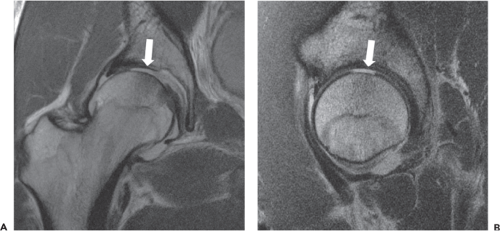 Figure 25.1. Coronal (A) and sagittal (B) FSE images of the hip in a 26-year-old man following traumatic posterior hip dislocation demonstrate focal traumatic chondral shear (white arrows) over the superomedial femoral head and acetabular dome. |
Synovium
Pathologic processes affecting the synovium may also be detected utilizing high-resolution noncontrast MRI. Commonly encountered findings include small effusions and reactive synovitis in the setting of intra-articular pathology, while less common entities include inflammatory arthropathies and synovial proliferative disorders. Synovitis manifests
as varying degrees of synovial thickening and hyperintensity, which, in the setting of severe inflammation, may be pronounced. Septic arthritis is one example of a process which typically leads to a marked inflammatory synovitis, generally resulting in a somewhat lamellated appearance of the hyperintense and thickened synovium; ancillary findings, such as soft tissue edema and lymphadenopathy, provide additional clues to diagnosis. Synovial proliferative diseases include entities such as pigmented villonodular synovitis (PVNS) and synovial chondromatosis. The classic MR appearance of both diseases is that of numerous intermediate intensity intra-articular bodies of relatively uniform size, which, when disease becomes confluent, may create a cast-like appearance in which individual bodies are difficult to discern. Due to hemosiderin content within the proliferative synovium, PVNS typically contains hypointense foci, which display blooming on gradient recalled echo sequences related to local dephasing, allowing differentiation from synovial chondromatosis. Due to high intra-articular pressure within the hip joint, advanced synovial proliferative disease may result in rapid erosive changes, particularly at the femoral neck, thereby placing the patient at risk for fracture (Fig. 25.4) (19,20,21,22).
as varying degrees of synovial thickening and hyperintensity, which, in the setting of severe inflammation, may be pronounced. Septic arthritis is one example of a process which typically leads to a marked inflammatory synovitis, generally resulting in a somewhat lamellated appearance of the hyperintense and thickened synovium; ancillary findings, such as soft tissue edema and lymphadenopathy, provide additional clues to diagnosis. Synovial proliferative diseases include entities such as pigmented villonodular synovitis (PVNS) and synovial chondromatosis. The classic MR appearance of both diseases is that of numerous intermediate intensity intra-articular bodies of relatively uniform size, which, when disease becomes confluent, may create a cast-like appearance in which individual bodies are difficult to discern. Due to hemosiderin content within the proliferative synovium, PVNS typically contains hypointense foci, which display blooming on gradient recalled echo sequences related to local dephasing, allowing differentiation from synovial chondromatosis. Due to high intra-articular pressure within the hip joint, advanced synovial proliferative disease may result in rapid erosive changes, particularly at the femoral neck, thereby placing the patient at risk for fracture (Fig. 25.4) (19,20,21,22).
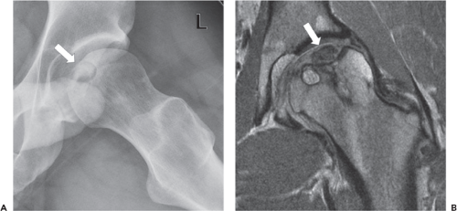 Figure 25.2. Frog lateral radiograph (A) and coronal FSE image (B) of the hip in a 41-year-old man with hip pain demonstrate a chronic osteochondral lesion of the femoral head (white arrows), with a mature bed of sclerotic bone, hypointensity of marrow signal indicative of devitalization, and partial thickness loss of overlying cartilage. |
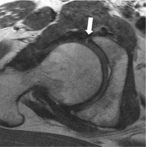 Figure 25.3. Oblique axial FSE image of the hip in a 43-year-old woman demonstrates a nondisplaced tear of the anterior labrum (white arrow), manifesting as a fluid signal intensity linear defect across the base of the labrum. |
Extracapsular Structures
In addition to assessment of intra-articular pathology, MR imaging simultaneously provides evaluation of surrounding extracapsular structures, including bones, muscles and tendons, bursae, and neurovascular structures which may also serve as pain generators. Commonly encountered entities include abductor tears, trochanteric bursitis, athletic pubalgia, and pelvic stress fractures. Given the commonly encountered clinical scenario of nonspecific hip and/or groin pain, the ability to noninvasively differentiate intra-articular versus extra-articular pathology is valuable in developing an appropriate treatment strategy (20).
Cohorts at Risk for Early Osteoarthritis
Certain pathologic entities place the patient at risk for the development of early osteoarthritis (OA). Recognition of
these entities prior to the development of osteoarthritis allows early intervention, with the goal of halting chondral wear and preserving the joint (1,23,24).
these entities prior to the development of osteoarthritis allows early intervention, with the goal of halting chondral wear and preserving the joint (1,23,24).
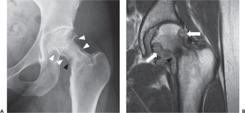 Figure 25.4. Frontal radiograph of the hip (A) in a patient with hip pain demonstrates indolent osseous erosions of the femoral head and neck (white arrowheads), suggesting a proliferative synovial process. Coronal FSE image (B) demonstrates numerous isointense bodies filling the joint space (white arrows), consistent with synovial chondromatosis; note associated insufficiency fracture of femoral neck (black arrowheads). |
Impingement Syndromes About the Hip
FAI is a complex entity in which a structural predisposition results in impingement of the femur against the acetabular rim, yielding a variety of abnormal forces which act upon the articular cartilage and acetabular labrum, ultimately resulting in early chondral degeneration. Classically, FAI is subdivided into two types: cam and pincer. In cam-type FAI, insufficient offset of the femoral head–neck junction results in its impingement upon the acetabular rim, while in pincer type, impingement results from acetabular overcoverage of the femoral head. In reality, elements of both types are often present within the same hip, and impingement may coexist with other structural issues such as developmental dysplasia of the hip (DDH). In addition, typical imaging manifestations of FAI often differ between males and females. While males more commonly present with a classic cam lesion, females often present with subtle femoral neck sclerosis or periosteal new bone formation, often in the setting of coxa valga, or superimposed upon an element of DDH. Given its variable imaging appearance, FAI can prove a challenging diagnosis, and, furthermore, imaging signs of impingement do not always correlate clinically with the presence of hip pain; therefore, imaging findings should always be interpreted in the context of the patient’s clinical presentation (23,25,26,27).
Related posts:


Stay updated, free articles. Join our Telegram channel

Full access? Get Clinical Tree


