Fig. 11.1
Ortholock anchored to the femur and to the tibia with two bi-cortical pins
Anatomical Survey
This is one of the basic step of navigation, specially in the systems imageless based; in fact all the surgical femoral and tibial references have defined by digitizing some anatomical landmarks. The accuracy of these references is strictly related to the accuracy of our landmarks digitization. Moreover it is very important to know how the reference axis and plane has been defined by the software [10]. Below the femoral and tibial references has shown about the Stryker Knee Navigation System, Version 4.0.
Femur Anatomical Survey
By digitizing femoral landmarks the following axes and references are defined:
Mechanical femur axis
Femoral rotation axis
Reference for resection level in the distal and posterior femur
Reference for anterior notching
Reference for automatic sizing, implant positioning, and for medio-lateral overhang
The mechanical femur axis is defined by the line from the hip center and the knee center. The hip center is calculated through a slow and smooth circumduction of the hip avoiding pelvic motion, while the femur center is directly digitized with the tip’s pointer at the center of the trochlear sulcus anterior just above the intercondylar notch (Fig. 11.2). The mechanical femur axis so defined is the reference for varus/valgus and flexion/extension alignment.
Fig. 11.2
The femur center is digitized with the pointer’s tip at the center of the trochlear sulcus anterior, above the intercondylar notch
The femoral rotation is defined as the average rotation axis calculated by the digitized transepicondylar axis (medial and lateral epicondyle), and Femoral AP axis. The medial and lateral epicondyles are directly digitized with the tip’s pointer respectively at the sulcus of the medial epicondyle and onto the most prominent point of the lateral epicondyle. The femoral AP axis is calculated by aligning the pointer’s axis with the most posterior point of the trochlea and the most anterior point of the intercondylar notch, also referred to as Whiteside’s line [2, 6] (Fig. 11.3).
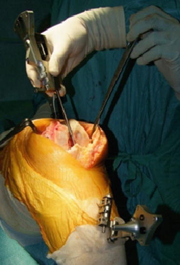
Fig. 11.3
The femoral AP axis is calculated by aligning the pointer’s axis with the most posterior point of the trochlea and the most anterior point of the intercondylar notch
The reference for the distal femur resection level is the most prominent distal point of the digitized condyle. It is important, that the most distal aspect of the condyle has been included in the points cloud digitized in order to avoid wrong resection thickness. The same procedure is performed to calculate the reference for the posterior resection level.
The reference for the anterior notching is defined during point acquisition of the anterior aspect of the distal femur. The points cloud of this digitization has include the portion of the anterior aspect below the expected saw blade exit points, to avoid wrong calibration of the level of anterior notching.
The reference for automatic sizing and femoral implant positioning, as in conventional technique, are the anterior cortical bone and the posterior femoral condyles. The purpose of the calculations is to achieve the best anterior match while keeping the implant size as small as possible. Moreover with the required digitization of the medial and lateral overhang femoral regions the software will provide, in numerical value, the average medial/lateral overhang or uncovered bone cut [10].
Tibial Anatomical Survey
By digitizing tibial landmarks the following axes and references are defined:
Mechanical tibia axis
Tibial rotation axis
Reference for resection level in the proximal tibia
The mechanical tibia axis is defined by the line from the tibia center and the calculated ankle center. The tibia center is directly digitized with the tip’s pointer onto the middle of the interspinous sulcus anteriorly near the anterior mid footprint of the ACL attachment, while the ankle center is calculated by dividing the digitized transmalleolar axis according to the ratio of 56 % lateral to 44 % medial. The transmalleolar axis is the line between the most prominent point of the medial and lateral malleolus directly digitized with the tip’s pointer. The mechanical tibia axis so defined is the reference for varus/valgus and flexion/extension alignment (Fig. 11.4).
Fig. 11.4
The mechanical tibia axis is the reference for varus/valgus and flexion/extension alignment
The tibial rotation axis is calculated by aligning the pointer’s axis with the midpoint of the posterior cruciate ligament (PCL) and the medial third of the tibial tuberosity. This axis is the reference for rotational alignment of the tibial component.
The reference for the proximal tibial resection level is the most recessed point of the digitized compartment. It is important, that the lowest aspect of the compartment has been included in the points cloud digitized, and that the pointer does not to digitize below the lowest anatomical point, in order to avoid wrong resection thickness [10].
Intra-operative Planning
After completion of patient registration, the software will calculate the size and position for the best fitting implant and place it on the virtual femur. Varus/valgus and rotational alignment are set to 0° respectively to the calculated mechanical axis, and to the average rotation axis calculated by the digitized transepicondylar axis (medial and lateral epicondyle), and femoral AP axis. The distal and posterior condyles are reconstructed in accordance to the principles of measured resection technique. If the gap balance technique is preferred, is possible changing the plan of the rotation of the femoral component after the distal femur resection and proximal tibia resection are performed. Once the intra-operative planning is displayed on the screen, the surgeon can decide whether to accept or modify it, changing femoral size or position. As described in Figs. 11.5 and 11.6, it is possible to change the orientation of the femoral component, to shift it in craniocaudal or anteroposterior direction, and to change the femoral size. Whenever a change in the position or in the size of the femoral component is performed, it is possible to verify the result of this change respect to the gap balancing, if it is caused an anterior notching, or if there is a medio-lateral overhang of the component respect to the bone.
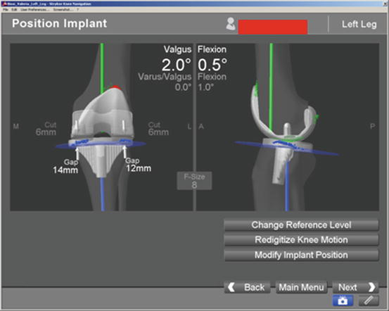
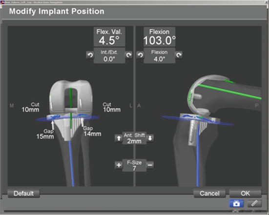
Fig. 11.5
The valgus and flexion can be changed during navigation
Fig. 11.6
The shift in craniocaudal or anteroposterior direction and the femoral size may be changed during navigation
During this phase to keep in mind the pre-operative deformity is crucial, because the surgeon can adjust the intra-operative planning to correct the deformity; for example, in a severe flexion deformity a greater distal femoral cut with reduction of femoral flexion can be planned respect to a standard posterior cut. At the end of this phase the “Planned Femoral Implant” dialog appears on the screen, summarizing size, alignment and position of the calculated femoral implant [10].
Jigs Navigation
When the intra-operative planning has been ended, the surgeon starts with cutting jigs navigation following his preferred technique. In this case the “free-hand technique” will be shown because it could provide a fast and accurate positioning of the cutting guides after a little bit of practice. This technique provides the manual orientation of the jig controlled directly on the monitor by the first operator, while an assistant fixes the jig with drilling pins (Fig. 11.7).
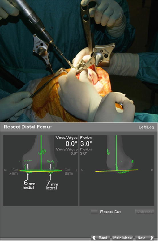
Fig. 11.7
The orientation of the jig is controlled directly on the monitor by the first operator, while an assistant fixes the jig with drilling pins
Usually the distal femoral resection is performed at 0° respect to the femoral mechanical axis, with 0–5° of flexion, in order to avoid anterior notching of the femoral cortex, and with 8 mm of resection depth from the most distal femoral condyle, to restore the thickness of the distal part of the femoral component; in this case a Scorpio NRG implant (8 mm of thickness) has been used. In some particular cases the amount of the distal femoral resection can be modified: when a patella baha is present, it is recommended to reduce the amount of this resection, and to increase the proximal tibial resection; while in a flexed knee it is recommended to increase this resection respect to the femoral posterior cut and to reduce the femoral flexion.
The femoral rotation, and the AP positioning of the 4-in-1 cutting block is performed by the “navigated drill templates for AP alignment” (Fig. 11.8). The navigated drill templates can replace the conventional AP sizer. By this dedicated jig it is possible to check the position of the femoral component as previously planned matching the position of the yellow line (jig orientation) to the green (planning orientation) lines. If a gap balance technique is preferred, is possible performing the tibial cut first, and then, with the medial and lateral collateral ligaments in tension, align the posterior femoral cut to the proximal tibial cut. Before fixing the jig the system confirms the presence or not of anterior notching. In this case it is possible to translate anteriorly the guide, checking the posterior resection that could be too large.
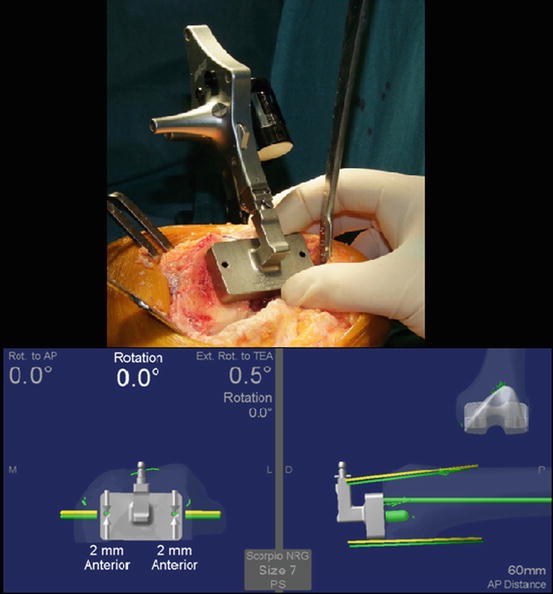
Fig. 11.8
 Virtual Preoperative Planning
 Computational Image-Guided Technologies in Cranio-Maxillofacial Soft Tissue Planning and Simulation
 Patient-Specific Instruments in Orthopedics
 Virtual Cranio-Maxillofacial Surgery Planning with Stereo Graphics and Haptics
 Navigation in Spinal Surgery
 3D Projection-Based Navigation


The femoral rotation and the AP positioning of the 4-in-1 cutting block is performed using the navigated drill templates for AP alignment
Related posts:
Virtual Preoperative Planning
Computational Image-Guided Technologies in Cranio-Maxillofacial Soft Tissue Planning and Simulation
Patient-Specific Instruments in Orthopedics
Virtual Cranio-Maxillofacial Surgery Planning with Stereo Graphics and Haptics
Navigation in Spinal Surgery
3D Projection-Based Navigation
Stay updated, free articles. Join our Telegram channel
Full access? Get Clinical Tree
