Fig. 6.1
The output of a depth sensor visualized in a two-dimensional picture. A person is sitting in front of the sensor. Some parts are registered to be space occluded by objects
6.2 Representation of Exercises
When describing the representation of exercises, it has to be differentiated between fine grained movements and more basic movements involving arms. When performing exercise that makes use of the fine motor skills of a patient, sensors may not be capable of capturing every delicate motion. Therefore, a model of the exercise has to be conceived which incorporates the basic movement in a simple manner. When using gross motor skills, the depiction of the exercise can be more sophisticated. In both cases, the number of exercises that may be wrongly recognized as having been carried out incorrectly has to be minimized. In the same fashion, exercises that are inadvertently identified as having been performed correctly should be minimized as well. By minimizing both false negatives and false positives, two goals can be achieved.
First, false positives distort the actual performance of a patient. Second, false negatives can be very frustrating for the patient. When performing a training in the right way but failing nonetheless, the patient may lose her/his interest in exercising.
In the following sections, the different approaches to represent basic and more sophisticated movements are presented.
6.2.1 Basic Movements
Very basic movements can be represented by basic techniques that check for the distance of a section of the camera’s field of view. The distance could be tested for either just one point or an area. The area’s shape depends on the exercise. This approach can also be used to detect objects without identifying them.
Every exercise is defined by a starting position and an ending position. In a training session, movements are often repeated. The motion from the starting position, across ending position, and back to the starting position could be repeated for a number of times.
An example for such an exercise would be the training of the dorsiflexion against gravity. In this exercise, the patient’s forearm is resting on a wedge-shaped cushion. The wrist is positioned on the top edge of the wedge. In this position, the palm can be moved upwards and downwards. With the camera having a direct view on the palm of the hand, the exercise can be checked by considering the distance to the nearest object above the cushion.
Another approach is needed for more sophisticated movements, i.e., involving multiple body joints.
6.2.2 Sophisticated Movements
Sophisticated movements cannot simply be inferred from the raw data of a depth sensor. The data needs to be processed intelligently before interpreting it. For most of the body movements, it is advisable to use a library like Kinect for Windows or OpenNI that is able to detect a human body in the point cloud given by a depth sensor. The body or parts of the body are projected onto a stick figure, a skeleton, in three-dimensional space. This skeleton is not to be confused with the anatomical skeleton in the human body. The skeleton does not differentiate between ell and radius, the bones in the forearm. There is just one edge between wrist and elbow. The number of body joints detected by a skeleton detection algorithm depends on the library that is used (Fig. 6.2).
Fig. 6.2
The body joints detected by a skeleton detection algorithm from Microsoft. The dots indicate the detected joints
An exercise consists of a starting position and an ending position. The movement between these positions is a record of snapshots. In order to make the recordings comparable to later exercises, a few modifications are made. The absolute positions of the limbs have to be softened to be comparable. This is done by converting the edges between the body joints into vectors. Through simple vector conversion, some improvements to the data can be made. By extracting the alignment of the patient’s upper body towards the camera, the vectors can be rotated around the vertical axis. This may be useful, if the patient is turned slightly to the left side or the right side.
Every human being has her/his own trademarks when moving around. Therefore, exercises are fitted specifically for each person.
The accuracy of the motion could be improved when recording the exercise multiple times. But this raises a few problems. As the patient will improve his performance over time, the exercise has to be recorded again to incorporate the improvements. Recording an exercise for 30 times in a row may annoy the patient. Other techniques have to be used to reduce the number of supervised recording sessions.
In summary, exercises are represented as a sequence of vectors. The vectors indicate the direction of the edges between body joints. The body joints are an abstraction of the skeleton of the human body captured by a depth sensor.
6.3 Evaluation of Exercises
The evaluation of basic movements using distance is quite simple. When using a point as a reference, the evaluation involves just one checking of the distance. When using a geometric shape one could either use the arithmetic mean of the points in the area or another kind of average. A weighted mean could focus on certain point of the area chosen for evaluating the training.
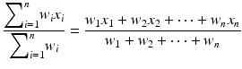
In an area with n points, the point x i exists for all i. Every x i has a weight w i .
When dealing with a more sophisticated exercise involving multiple body limbs, another approach is needed. With the skeleton detection algorithms multiple goals are desirable. Primarily, the correctness of the exercise in general is a goal. Secondly, the lookout for indications of compensations made by the patient is desired.
6.3.1 Correctness of an Exercise
In general, a recorded exercise is compared to current online data when performing an exercise. As every movement differs from another, a threshold for successfully performing the exercise is allowed.
An abstract skeleton is identified by a skeleton detection algorithm and divided in vectors connecting the body joints (see Fig. 6.4). Each of the vectors is separately compared to the previously recorded exercise. This has two advantages. The conversion to vectors eliminates the need for the patient to sit at the exact same spot every time. Furthermore, a failed performance can be attributed to one of the vectors and hold as a basis for further analyses.
The vectors are compared by calculating the angles between them. A threshold determines how accurate angle has to be and thus how accurate the exercise has to be performed.
Further mechanisms allow for performing the exercise faster or slower. In some cases it may be possible that the patient does hesitant or jerky movements in either the wrong or right way. The evaluation allows for multiple states of progress. Therefore, such deviating moves are possible up to a certain degree.
The correctness of an exercise is determined by a state machine with various rules (see Fig. 6.3). This state machine is triggered when a patient is either in the starting position or in the ending position of a recorded exercise. Both positions mark the most important pieces of information. The starting point is obviously the beginning of the exercise, but the end position may indicate a fully performed exercise that has not been properly detected. This could happen for a variety of reasons like an abnormal skeleton detection.
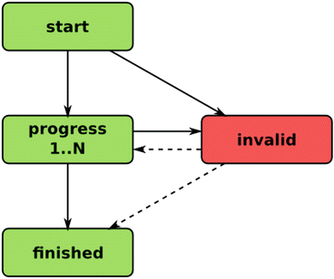
Fig. 6.3
The simplified state machine for an exercise. Each box represents a state or a series of states. An exercise starts in the state start and ends with either the invalid state or finished state
The rules of the state machine allow more than one state being active at the same time. This increases the robustness of the detection because smooth movements may not be expected from stroke patients. State transitions allow starting position, monitoring progress, small movements in the wrong direction, temporarily remaining in a fixed position, failing an exercise, and finished exercise.
The progress of an exercise is matched with the recorded exercise. If a recorded exercise consists of N snapshots, the progress is tracked in N steps with 1 being the starting position and N being the end position. Movements in the wrong direction may be possible by trembling. This is caught by considering more than one progress state. Short pauses are covered as well. Failing a number of positions does not necessarily mean for the exercise to fail overall. Reaching the end position can indicate a successfully performed exercise.
The state machine is maintained for all vectors involved in the training. Figure 6.4 shows all body parts of the upper body. The individual state machines for each vector are interlinked to give an estimation of the patient’s performance. Either the exercise has been performed or it has been partially performed. In the latter case, the last position in compliance with the training is identified. The percentage of success can be calculated and used to evaluate the performance further.
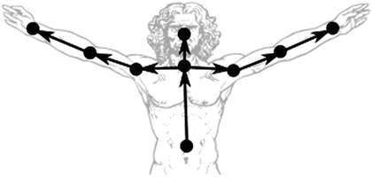
Fig. 6.4
The vectors of the upper body created for exercise evaluation are represented as arrows. The dots represent the body joints detected by a skeleton detection
Additionally, typical movements or gestures are identified to give a direct feedback as the patient may not be aware of the fact that he is doing something wrong. These compensations are monitored separately.
6.3.2 Compensations
Compensations are gestures or movements that are done automatically to compensate for a lack of fine motor skills. Avoiding compensations is part of the rehabilitation process of stroke patients.
When detecting compensations one is looking out for some indications. Basis for detecting a compensation in this model of an exercise are the compensations associated with the exercise, the recorded exercise, the behavior of the stroke unaffected side, and a reason why an exercise failed.
Exercises chosen are in most cases already linked to specific types of compensation. Therefore, this can be considered as an important input when trying to detect compensations on the fly. A previously recorded exercise under the supervision of a therapist serves as a basis for any derivations from the intended movements. The supervised recording means the patient’s best performance. The behavior of the unaffected side may also indicate compensations when a detection on the affected side fails for some reason. For example, the ipsilateral and contralateral flexion of the torso may be indicated in both sides of the body.
When performing an exercise, like extending an arm, the exercise may fail. By comparing the recorded exercise with the performance, a conclusion could be made on the vector and its direction. All these factors can be brought together in a logical causal context. This is done by using a rich declarative language approach called Answer Set Programming (ASP).
The knowledge representation and reasoning system allows for describing a problem in logical and easy way. This permits quick changes without a lot of costs. An optimized universal solving process resolves consequences and constraints until a solution, an answer set, has been found. Additionally, the maximization or minimization of certain aspects allows for a solution tailored towards the needs of a patient.
The complexity of the compensation reasoning has to be matched to the requirement of real-time feedback in the StrokeBack system. The average response time of the underlying reasoning system depends on the number and cross correlation of compensation features. The system used in the StrokeBack project weights up the performance against the complexity of tasks.
The detection of compensations is performed by a declarative programming oriented towards search problems. As an outgrowth of research on the use of non-monotonic reasoning in knowledge representation, it is particularly useful in knowledge-intensive applications [3]. The knowledge base is developed in cooperation with therapists. Background information like typical compensations in an exercise, mean to spot a compensation, and cross-correlations between compensations serve as a base for the reasoning. Compensations are often tied to certain exercises, e.g., the elevation of the scapula can be seen on the stroke affected side when lifting an object with the affected arm. The description of the compensation is also based on the representation model of the body. When comparing the shoulder vector of an elevated scapula with the reference vector of straight shoulders, a difference in the vertical axis is recognized. This deviation is monitored over time and a differentiation between an elevation and a protraction of the shoulder is estimated. All rules are provided with a weight depending on the exercise. For example, when lifting an object straight into the air, a protraction of the scapula may be more likely than a rotation of the body, although both scapula protraction and body rotation have a similar appearance in the representation model. In both cases, the shoulder of the affected side is pushed towards the front. Furthermore, compensations like elevation of the scapula and the lateral flexion towards the unaffected side are occurring together when lifting an object. When detecting interrelated compensations, the accuracy of the compensation diagnosis is increased. Adjusting the weights in consultation with the therapist increases the accuracy further.
The knowledge base and rules developed in cooperation with therapists are merged with the output of the performed exercise. A universe of all possible diagnoses is created. The problem is transformed into a search problem with the goal to find the most accurate compensation diagnosis. This also includes a perfect execution without any kind of compensation. An optimized search algorithm with learning abilities reasons on the underlying data. The search tree is pruned by conflict-driven clause learning (CDCL). See [4] and [5] for more details. The answer set is found by making a decision on the depth-first search. The clauses (nogoods) leading to a dead end in the search space are stored and the algorithm jumps back to the last decision level. The learned nogoods prevent the search algorithm to making same mistakes again. Clause learning can lead to n learned clauses with n being the number of atoms in a logic program. Rules consist of one or more atoms. The worst case size of learned clauses therefore is O(n). Different decision methods and variations of the algorithm influence the runtime of the search. A real-time compensation detection is therefore feasible.
6.4 The Exercise Design Tool
The general purpose of the exercise design tool is to support physical therapists to design individual exercises for stroke rehabilitation patients. It also acts as an interface to a versatile answer set solving system which permits the real-time evaluation of these exercises. Furthermore, the tool should be easily integrated into the whole StrokeBack system.
In principle, the exercise design tool’s graphical user interface is not needed when the tool is fully integrated into an environment. The tool can be configured via TCP socket messages only. But a graphical user interface proved very useful in the prototyping process.
A physical therapist needs a simple to use tool which is nonetheless empowers her or him to design exercises for individual patients. Not only a movement of the upper body should be captured and compared to previously performed exercises, but also it should be able to detect different movements at the same time. The explicit description of a posture which should be avoided may be necessary.
Another aspect of the exercise design tool is the interface to the tools of the Potsdam Answer Set Solving Collection (Potassco) [6]. ASP and answer set solving is used to evaluate exercises. Thus, a tight integration is desirable.
Furthermore, the tool should easily integrate into the StrokeBack system. On the contrary, it should work on its own to permit testing the exercise evaluation via ASP. Therefore, at least two means of control may be necessary to implement: a graphical user interface for testing and a library to enable the tool’s features to other programs. It is important that the required versatility and flexibility is reflected in the tool’s architecture.
This section discusses the tool’s key features, hardware and software requirements, design decisions and interfaces. Additionally, a method to make the comparison of movements less difficult is presented in detail. And last but not least, the steps necessary to design an exercise are explained.
The tool’s general purpose is to capture and evaluate exercises performed by stroke rehabilitation patients. The tool captures the upper body of a person sitting in front of the depth sensor, e.g., the Microsoft Kinect. The evaluation of the exercise is done using ASP. An answer set solver is called repeatedly with updated data to allow for real-time feedback.
An exercise may consist of one or more movements of the upper body’s limbs. Each movement may result in a different output, e.g., the explicit recording of movements which should not be performed by the stroke rehabilitation patient is possible.
The design tool should offer certain key features to fulfill the requirements of a physical therapist as well as the requirements given by the environment or other applications. Thus, the tool should allow displaying the depth sensor image, recording movements performed in front of the depth sensor, selecting one or more movements which should be recognized, saving and loading previously recorded movements, selecting the joints of the upper body which are important for the exercise, selecting the answer set program used to evaluate the exercise, repeatedly calling an answer set solver to display real-time feedback, changing the frequency of depth sensor to increase performance, writing a log file to permit investigation of previously performed exercises, adjusting the preciseness of the exercise evaluation, displaying individualized output for an exercise, stopping the sensor’s data stream to save power and cool down sensor, and controlling the depth sensor’s tilt motor if necessary.
The identified key features had influence on the design of the graphical user interface as well as the general architecture of the tool.
The fundamental principle of the tool is to provide a versatile interface for physical therapists as well as other applications. Therefore, the tool supports a range of input and control means. The tool allows the use of a graphical interface, start parameters, and also offers a whole interface library which allows the input and output via other applications.
A graphical user interface enables the user use all the features of the tool with simple mouse clicks and keyboard input. Start parameters permit the user to automatize the process of evaluating exercises. The joints chosen for the exercise, the answer set program used for evaluation, and so forth can be configured when starting the program by using the predefined start parameters. With each start of the program, the parameters can be configured to fit the exercise which should be evaluated.
The start parameters can be used to start the design tool without the graphical user interface. In this case, the fully operational design tool will run in the background and can be controlled by another application. In order to do this, a interface library was created. This library supports all functionality of the design tool, e.g., recording a movement, saving and loading movements, and selecting evaluation programs. The interface library can be used to either implement another graphical user interface or to fully incorporate the design tool’s features into another application.
The tool can either be restarted for each exercise or run once and configured for each exercise on-the-fly. Having the possibility of running the tool in background over a longer period of time, the necessity to turn off the depth sensor may come in handy to prevent overheating the sensor or consuming too much power. Therefore, the decision was made to include means to turn on and turn off the data stream of the sensor.
The answer set solver is called repeatedly to incorporate incoming data from the depth sensor on-the-fly. Therefore, the incoming data from the depth sensor is transformed to permit a more flexible comparison of movements. The process used to convert the coordinates is described later.
Depth sensors are able to detect more than one person in front of the sensor. In order to simplify the identification of the person who is performing the exercise, the decision was made to work with the person closest to the center of the sensor image. The sensor will have a fixed position. The person in the center of the image is most likely the stroke rehabilitation patient and not an intervening physical therapist or someone else. In the graphical user interface, the person identified for capturing movements is marked with a red dot.
6.4.1 Architecture
When taking the design decisions and key features into account, the tool’s architecture can be planned. The tool’s architecture is depicted in Fig. 6.5.
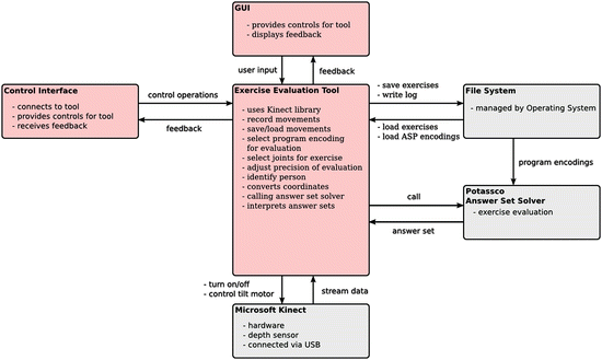
Fig. 6.5
The architecture of the exercise design tool
The system uses Microsoft Kinect or rather a Kinect library to control the depth sensor, i.e., Microsoft Kinect. The tool provides the means to record movements, save and load movements, select the programs used for exercise evaluation et cetera. The GUI is the primary input and output method. A control interface which uses the provided interface library can be used as an alternative. This control interface is implemented as a TCP socket in the final prototype. The socket connection is vital for the integration of the exercise design tool into the StrokeBack architecture. The file system which is managed by the Operating System is used to store recorded exercises as well as the program encodings used for exercise evaluation. The program encodings are used by the answer set solver which is called repeatedly to return a live feedback to the tool. This feedback is interpreted by the tool and can be displayed in the graphical user interface or a control interface which uses the already mentioned interface library.
Not shown in the figure is the mean to display messages on the screen which can be displayed over other software like games. The messages can be individualized and are triggered by successful or unsuccessful events, e.g., a successfully performed exercise, a failed exercise, or compensation detected by the software. This functionality was added to allow for fast prototyping. The messages displayed in the overlay can also be transmitted via the TCP socket.
6.4.2 Coordinate Conversion
In order to easily compare an exercise with a recorded one, coordinates are converted to a unified coordinate system. The conversion allows for the deviation of the patient’s absolute position as well as the deviation of the patient’s angle towards the depth sensor (compare Fig. 6.6).
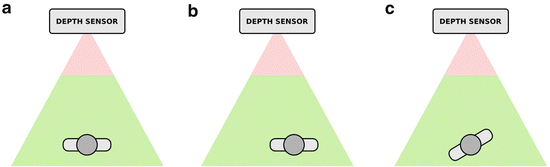
Fig. 6.6
Relative position and angle towards the depth sensor. In (a) a person sits in front of the sensor, in (b) the person is shifted slightly to the right, and in (c) the person’s upper body is rotated
The Kinect or a Kinect library respectively delivers a simplified bone structure to represent a person in front of the depth sensor (see Fig. 6.4). The direction of the coordinate system’s axes is depicted in Fig. 6.7. The x-axis represents the horizontal planer, the y-axis represents the vertical plane, and the z-axis represents the depth.
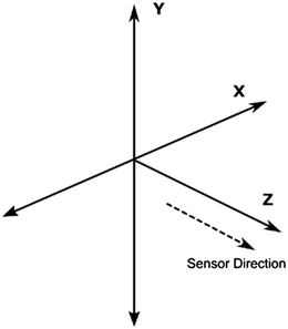
Fig. 6.7
The coordinate system of the Microsoft Kinect
A vector reaching from the left to the right shoulder joint is created. This vector is used to calculate the angle φ between this vector v and the x-axis of the depth sensor.
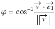
Therefore, unit vector  is used.

is used.Additionally, all body joints are rotated around the y-axis. Vector  is transformed to the vector
  .
.

is transformed to the vector .Furthermore, a vector reaching from the center of the coordinate system to the joint representing the shoulder center is calculated. This vector is subtracted from everybody joint delivered by the Kinect library. This is done to collapse the shoulder center joint and origin of the coordinate system.
6.5 Designing an Exercise
In this section, the steps a therapist has to perform to design a new exercise with the exercise design tool are explained. The same steps could be performed using the commands provided by the interface library. Assume that the stroke rehabilitation patient should perform an exercise with her/his affected left arm. The exercise consists of lifting the arm to a certain degree after the arm had rested on the desktop. The exercise is performed in front of the sensor.
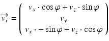
At first, the therapist starts the design tool and checks whether or not the patient is recognized by the depth sensor. Because the patient will take more than 2 s to raise her/his arm, the recording frequency can be lowered to 10 Hz. The therapist also assigns a name to the exercise (see Fig. 6.8). In the StrokeBack system, the name is composed automatically. The therapist does not have to bother about picking a name. Subsequently, the therapist selects the left side to be monitored (see Fig. 6.9). The preparations for the recording are finished with this step.
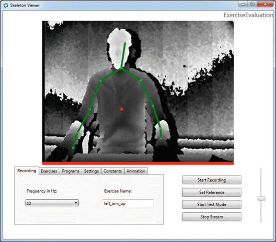
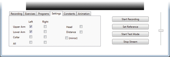
Fig. 6.8
The GUI of the exercise design tool. A skeleton is superposed onto the person in front of Kinect. The dot on a torso indicates person being recognized as the one performing the exercise
Fig. 6.9
Vectors representing the upper body of a patient can be selected in the GUI
The physical therapist asks the patient to rest her/his arm on the desktop. The therapist starts the recording by pressing on the button labeled Start Recording and gives a sign to the patient to start performing the exercise which was agreed upon. The patient raises the arm under the instructions of the physical therapist. When the patient has reached the desired height, the therapist can stop the recording by pressing the same button. If the movement has not been performed properly, the recording process is repeated until the physical therapist is satisfied with the patient’s performance. The exercise has been successfully designed.
The therapist may also check the record by initiating an exercise evaluation by pressing the button labeled Start Test Mode. When the movement is successfully recognized, the exercise can be repeated without the supervision of the therapist. If not, the therapist has the possibility to increase the derivation allowed when performing the exercise. There are multiple means to adjust the settings for exercises (see Fig. 6.10).
Fig. 6.10
Various settings for exercises and compensation detection in the GUI
Two variables can be adjusted to fit an exercise to a patient’s condition. The variable angle adjusts the allowed derivation from the originally recorded exercise. As the upper body is represented as vectors, the derivation from the recorded exercise can be given as an angle between any two vectors involved in the exercise. An exercise not necessarily fails when the derivation from the original recorded exercises is too high. Some movements made by the patient as well as measurement errors by the sensor should not fail the exercise. Some patients are allowed to vary their movements more than others. Therefore, the therapist can adjust the variable cDuration. This variable defines the maximal duration for stronger derivations. This variable is also used when detecting compensation movements.
6.5.1 Adjusting for Compensation
The exercise design tool was developed to also detect compensation movements made by stroke rehabilitation patients. The list of compensations includes contralateral and ipsilateral flexion, scapula protraction, scapula elevation, and the flexion of the torso.
With approaching new technology, other compensations could be added to the list of compensations supported by the prototype in the future.
Assume that a patient is training her/his fine motor skills in front of the Kinect. For each exercise the therapist is able to save a reference of the upper body. This reference represents a near ideal position in which the patient should perform the given exercise. The setup for such an exercise can be automatically configured by the StrokeBack system. In the graphical user interface, this can also be achieved by setting up a name, selecting the involved body vectors, and clicking the button labeled Set Reference (see Figs. 6.8 and 6.9). The process is very similar to the designing of an exercise. The variables in Fig. 6.10 can be set up for the specific needs and posture of a patient.
Every single type of compensation can be activated or deactivated for an exercise. If a compensation is actively surveyed, the therapist has the option to extend or restrict the movement until a compensation is detected.
The variable scapula elevation determines the angle allowed to derivate from the original reference. When the variable is set to 500 and the shoulder is lifted higher than 5°, a compensation may be present. In the same fashion, the variable scapula protraction can be used to determine the allowed derivation when pushing the shoulder forward. The variable ipsilateral flexion (or contralateral flexion) determines the allowed derivation when leaning towards the stroke affected side (or away from the affected side respectively). To measure the flexion of the torso, a little trick is needed. As the Microsoft skeleton detection algorithm only provides unreliable data for the spine (compare Fig. 6.4), the distance between patient and sensor is used as an approximate comparison value. The variable cDistance is used to represent the derivation from the original posture in centimeters.
Related posts:


Stay updated, free articles. Join our Telegram channel

Full access? Get Clinical Tree


