Fig. 17.1
Diagram of experiment field
The subjects used their right leg as a pivot for both the 45° and 90° turn, both of which were to the left Each trial was performed three times, each with a maximum effort. Before the performance the players were given a sufficient warm up and confirmation of the motion they were to do. All data were recorded. Sufficient rest time was given between trials to eliminate any effect of fatigue.
17.3.3 Measurement of Motions
Three-dimensional position coordinates of markers on the players were measured from three directions using three high-speed cameras (High Speed Exilim Ex-F1; Casio Computer Co., Ltd. Japan). Sampling frequency was set at 300 Hz. All camera tripods were equipped with a leveling gauge so that the motions could be photographed horizontally. Sensors that started the cameras at a light signal were used to synchronize the three high-speed cameras. To closely simulate the conditions under which injuries typically occur, the experiment was conducted on a rugby training field of artificial turf that was used to prepare for regular games. The subjects wore the same “used” spike shoes that they wore for regular rugby play.
A bar equipped with a leveling gauge was used for calibration. The calibration matrix involved a 2 × 2 m area, in which a total of 45 points were set, including 9 sites in 4 quarters at 1-m intervals, each of which had 5 positions in height at 50-cm intervals (0, 50, 100, 150, and 200 cm).
Before conducting measurements, markers were attached to bony landmarks on the subject to calculate angles and CG position. There were 23 attachment sites in total, which were the acromions (right and left), the manubrium of the sternum, the first thoracic spine, the lower end of the rib (right and left), the superior anterior iliac spines (right and left), the greater trochanters (right and left), the tibial tuberosities (right and left), the knee joint fissure gap (internal and external), the centers of the medial and lateral malleoli (right and left), the medial and lateral malleoli (right and left), and the fifth lumbar vertebra (Fig. 17.2). The subjects wore a body-contacting suit to which the markers were attached using double-sided tape.
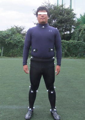
Fig. 17.2
The image of the locations of markers
17.3.4 Analysis
The photographs were taken using high-speed cameras equipped with image-processing software (Edius Neo3, Grass Valley USA). The images were further processed utilizing fetching by motion analysis software (Frame-DIASIV, DKH Co., Ltd. Japan) to calculate the 3- and 2-dimensional coordinate values of the markers using the direct linear transformation method.
Analysis of the knee motion and the CG was done at the time period of 40 ms immediately after foot grounding (which was set as 0 m), in accordance with a study (McLean et al. 2003) in which ground reaction force by side-step peaks was reported to peak at approximately 40 ms after grounding and another study (Koga et al. 2010) in which ACL injuries were reported to occur at 40 ms. The mean value calculated from the three trials was used in the data analysis as a representative value for each individual.
17.3.5 Analysis Items
The calculated dependent variables and the landmarks as well as the method used in their determination follow:
Flexion angle of the knee joint
The knee flexion angle was calculated from the 3-dimensional coordinate value of the greater trochanter of the grounding foot (right foot), the external fissure of the knee joint, and the lateral malleolus (Fig. 17.3).
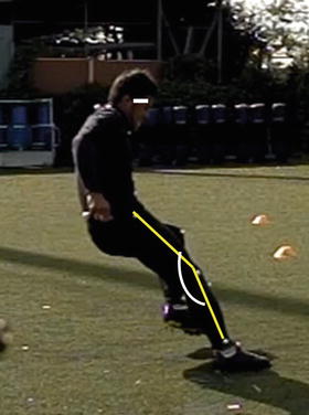
Fig. 17.3
The image of knee flexion
CG (rearward position: Y-coordinate; height: Z-coordinate)
The CG position was calculated from 23 points, which were the tip of the hand (right and left); the center of the hand joint (right and left); elbow joints (right and left); acromions (right and left); the tip of the toe (right and left); hallux balls (right and left); heels (right and left); center of the foot joint (right and left); knee joints (right and left); greater trochanters (right and left); and the upper end of the sternum, vertex, and tragion.
The rearward position was calculated from the Y-axis distance (centimeters) between the heel of the grounding foot and the CG (Fig. 17.4), whereas the height was calculated from the Z-axis distance (cm) between the ground and the CG (Fig. 17.5).
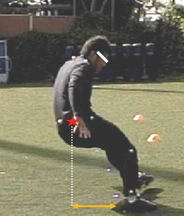
Fig. 17.4
The distance of backward center of gravity
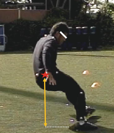
Fig. 17.5
The height of backward center of gravity
Abduction angle of the knee joint
The angle formed by the superior anterior iliac spine, center of kneecap, and center of foot joint (center of the line connecting both malleoli) was calculated on the frontal plane using the location’s 2-dimensional coordinate values, as reported in a previous study (Nagano et al. 2008) (Fig. 17.6).
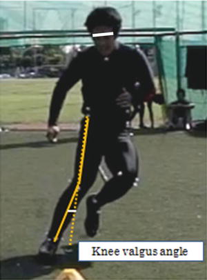
Fig. 17.6
The angle of knee abduction
17.3.6 Statistical Processing
The results are expressed as mean ± SD. Statistical calculations used the IBM SPSS statistics package (ver. 19.0 for Windows). A paired t test was used for significance testing; a probability of less than 5 % was considered sufficient to reject the null hypothesis.
Related posts:
 Injury and Illness Surveillance Among Olympic Athletes: Summary of the 2010 Winter, and the 2008 and 2012 Summer Olympic Games
Anterior Cruciate Ligament Injury Prevention in Female Adolescents
Concussion and Severe Head-Neck Injury: An Approach for Their Prevention in Rugby and Judo
Video Analysis of ACL Injury Mechanisms Using a Model-Based Image-Matching Technique
The Epidemiology of Low Back Disorders in Athletes
Sports Injury Surveillance in Japanese Junior and Senior High School Students
Injury and Illness Surveillance Among Olympic Athletes: Summary of the 2010 Winter, and the 2008 and 2012 Summer Olympic Games
Anterior Cruciate Ligament Injury Prevention in Female Adolescents
Concussion and Severe Head-Neck Injury: An Approach for Their Prevention in Rugby and Judo
Video Analysis of ACL Injury Mechanisms Using a Model-Based Image-Matching Technique
The Epidemiology of Low Back Disorders in Athletes
Sports Injury Surveillance in Japanese Junior and Senior High School Students
Stay updated, free articles. Join our Telegram channel

Full access? Get Clinical Tree


