Fig. 4.1
A load-controlled test apparatus to apply single or cyclic loads to multiple cartilage specimens. (A) Pneumatic air pistons to load the explants. (B) Piston rod with flat-bottom, cylindrical, porous polyethylene load platen. (C) Twenty-four-well explant holding chamber. An expand view of the load platen is shown on the right
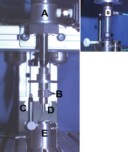
Fig. 4.2
A single-impact load-controlled test apparatus. (A) Pneumatic air piston to impact a single explant. (B) Piezoelectric load transducer. (C) Displacement transducer to measure explant deformation. (D) Piston rod with solid, cylindrical nonporous metal load platen. (E) Explant holding chamber. An expand view is shown on the right with a porous metal load platen
Biomechanically Controlled Systems to Injure Cartilage
Many mechanical factors can affect cartilage injury, including peak stress, peak strain, stress and strain rate, impact energy, and total loading time. In theory, it is better to examine all these parameters in order to accurately define the event during injury. However, in practice only three of these parameters can be independently controlled at one time. Thus, it is sometimes difficult to compare studies that use different control systems in which only selected parameters are reported. In this section, we describe three commonly used approaches: (1) load-controlled system, (2) displacement-controlled system, and (3) energy-controlled (drop-tower) system, and discuss the differences and advantages of each system.
Load-Controlled System
In a load-controlled system, a solid or porous load platen is utilized to apply a uniaxial compression to the surface of the articular cartilage explant, as shown in Fig. 4.2. The compression can be applied at a fixed loading rate (or stress rate) until the load reaches the designated maximum load (or peak stress) [17, 20, 35, 36]. This system can compress a cartilage explant with either a single impact load or multiple times (cyclically) using a defined waveform, such as a ramp or sinusoidal compressive waveform or one determined to simulate a gait cycle [22, 35, 37, 38]. In this system, the stress level on the specimen can be controlled even when multiple explants with different thicknesses are simultaneously loaded. The independent mechanical parameters that can be set or controlled with this type of system are the maximum load (peak stress), loading rate (stress rate), number of repeats or loading cycles, loading waveform, dwell time (on-off period), and total loading time.
Displacement-Controlled System
The second type is displacement-controlled system. Like the load-controlled system, one can choose to apply a defined displacement to the surface of articular cartilage at a given displacement rate (or strain rate) through a solid or porous platen. This displacement can be applied once [30, 39, 40] or multiple times [28] to reach a defined peak stress [41] or final strain [39, 40, 42]. When performing repeated displacement-controlled compressions, an offset displacement is often implemented to prevent the loss of surface contact (liftoff of the platen) during the unloading phase of the cycle due to the viscoelastic response of cartilage [43]. An electronic actuator with a spectrometer is commonly used to apply the prespecified displacement [43]. The system can easily load multiple samples at the same time with or without a lateral confinement. The independent mechanical parameters that can be controlled in this displacement-controlled system are the maximum deformation (peak strain), deformation rate (strain rate), number of repeats or deformation cycles, deformation waveform, dwell time (on-off period), and total deformation time.
Energy-Controlled (Drop-Tower) System
Probably the most commonly used method is the drop-tower type of apparatus. In this system, the specimen is impacted with a controlled amount of energy by dropping a known weight from a defined height above the surface of the specimen [15, 25, 44–48]. No separate controlled system (e.g., computer) is required, though an independent transducer and displacement transducers are often used to record the impact force and specimen deformation, respectively. This system can injure cartilage in a very short time interval, typically less than 5 ms [15, 49, 50] and at very high stress rates (5,000–80,000 MPa/s) and peak stresses (5–70 MPa), values close to those occurring in a joint injury from a motor vehicle accidents [15, 51, 52]. At these high stress and strain rates specialized accelerometers or force transducers, such as piezoelectric transducers, are required to record the injury event as shown in Fig. 4.3 [15, 46, 52]. In an impact energy-controlled system, the only controlled parameter is the impact energy (joule) or energy density (joule/cm2), that is, the fixed weight and height.
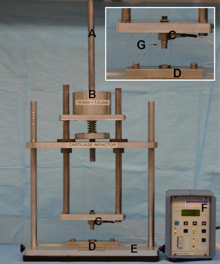
Fig. 4.3
A “drop-tower”-type test apparatus. (A) A cylindrical rod to guide and secure the mass during dropping. (B) Defined mass. (C) Piezoelectric load transducer. (D) Explant holding chamber. (E) Supporting frame and base. (F) Signal conditioner to amplify voltage generated by load transducer. (G) Nonporous metal load platen as shown in the insert
Confined Versus Unconfined Test Configurations
In normal and injured cartilage, interstitial fluid plays an essential role in resisting the applied load in a time-dependent fashion. The viscoelastic response of articular cartilage is well described by biphasic or poroelastic theories [53–55]. The flow of interstitial fluid through the extracellular matrix (ECM) and across the articular surface (exudation and imbibition) accounts for the viscous nature of the mechanical response of articular cartilage. This response is dependent on not only the elastic modulus of the solid matrix, but also the permeability of the solid matrix to resisting fluid movement though the solid matrix, which can occur in both the radial (depth) and transverse (tangential) directions. In confined compression, the cartilage specimen is usually cylindrical and placed into a tight-fitting, impervious cylindrical chamber such that a barrier to fluid flow is placed radially around the circumference of the specimen. When loaded in this configuration with a porous platen, the interstitial fluid is forced to flow in the axial direction passing through articular surface, and gives rise to a uniaxial compressive stress and strain in the ECM [29, 40, 52, 56]. In unconfined compression, the cartilage is compressed between two impermeable parallel platens, with the compression applied to the articular surface and either the underlying subchondral bone or the cut surface of the cartilage if the bone is removed. The sides of the cartilage are open to allow fluid transport, thus allowing the cartilage to bulge at the outer perimeter to exude and imbibe fluid in the radial direction [57, 58]. The decision to choose between confined and unconfined loading in a cartilage explant model depends on the hypothesis and assumptions in the experimental design [28–30, 34, 37, 40, 52, 59–61]. This is especially important for cartilage loading experiments performed in long-term culture where an adequate nutrient supply is needed [22, 34, 60]. In a single impact experiment, local interstitial fluid flow and ECM stress and strain are transient and if not laterally confined may result in nonuniform matrix and cellular damage or even cell death [13, 49, 62, 63].
Threshold Stress to Kill Chondrocytes
Using different loading systems, many studies reported the minimum stress or stain required to kill chondrocytes, one of the most important benchmarks for PTA. In the last 15 years, most researchers have chosen nonradioactive methods to measure cell death/viability, such as cell metabolic dyes or membrane-impermeable dyes [33, 37, 64–67]. One limitation of these methods is that after injury some chondrocytes are metabolically inactive with a leaky membrane and appear dead (false negative) while other cells undergoing apoptotic pathways may appear alive (false positive) for days. Delayed cell death or apoptosis is one of the major pathways for chondrocyte death in injured cartilage [23, 28, 68], and will be discussed in a greater detail later in this book.
Using a load-controlled system, Torzilli et al. loaded cartilage explant at a stress rate of 35 MPa/s and found that the threshold stress to kill chondrocytes at the time of impact (acute) was 15–20 MPa [36]. Matrix damage with apparent rupture of the collagen fiber matrix was also found at the time of impaction. The threshold stress of 15 MPa was also found to kill chondrocyte when cartilage explant was compressed by a single impact at 350 MPa/s [35]. Using a displacement-controlled system with a final strain of 50 %, Kurtz et al. [39] found no cell death when cartilage was loaded to 12 MPa at a stain rate of 0.01/s. However, dead cells with matrix damage were found when loaded to 18 MPa and 24 MPa with faster strain rates of 0.1/s and 1/s, respectively. D’Lima et al. [59] found that a static compression of 14 MPa applied over 0.5 s induced cell apoptosis which was inhibited by broad-spectrum caspase inhibitors.
The threshold stresses found for cell death in these studies are much lower than those reported using a drop tower [15, 26, 63]. Jeffrey et al. [26, 63] found that a threshold stress of 50 MPa was needed to induce matrix damage and chondrocyte death when cartilage was impacted at strain rates of 1,600–2,300/s [26]. These findings highlight the differences in impact loading between a drop-tower and the other two controlled systems [51].
In repetitive overloading tests, the threshold stress to induce cell death and tissue damage was found at lower levels. Farquhar et al. [24] loaded canine cartilage explants cyclically at 100 MPa/s for 30 min and found subtle damage in most explants at 5–10 MPa compression. They also found that increased tissue swelling and fibronectin biosynthesis were associated with matrix damage. Loening et al. [28] found that a minimum stress of 4.5 MPa was needed to induce cell death and tissue swelling when immature bovine cartilage explant was compressed to a final strain of 30–50 %. They also found that chondrocyte apoptosis occurred at lower stresses than those required to stimulate cartilage matrix degradation and biomechanical changes. Chen et al. [22] loaded cartilage for 48 h and found chondrocyte death along with denatured collagen from a repetitive stress of 1.0 MPa. This was consistent with a study by Steinmeyer et al. [69] who found 7–14 % cell death after 6 days of repetitive loads of 1–5 MPa. This was only 8 % of the threshold stress found for a single impact [39, 56, 70].
In all loading systems, cell death is always found in articular cartilage adjacent to the cracks [15, 22, 26, 35, 67] where high shear stress is expected. When a full-thickness cartilage or an osteochondral explant is used, cell death usually appeared first in the superficial zone [15, 26, 56], the zone in articular cartilage with the lowest compressive modulus [71]. Together, these studies conclude that high compression and high shear in a single impact are important factors for acute cell death and matrix damage in articular cartilage, and that chondrocytes in the superficial zone are more vulnerable to mechanical injury. High compressive and shear forces and stresses are common in vivo events when joints are subjected to sudden and high-energy impact loads, such as with the rupture of anterior cruciate ligament during sports activities, falls from a height, and vehicle accidents. Based on in vitro studies, similar types of articular cartilage damage (cell death and ECM cracks) in the superficial and deeper zones would be expected to occur in vivo at the time of joint injury.
Loading-Rate-Dependent Cell Death and Matrix Damage
One of the important features in cartilage injury is that cell death and matrix damage are dependent on the loading rate and loading time [39, 56, 70, 72]. In a study by Ewers et al. [72], there was a greater amount of cell death in cartilage explants impacted with a stress of 40 MPa compression at 40 MPa/s compared to cartilage impacted at 900 MPa/s. In a systematical study of stain rate, Morel and Quinn [40] loaded cartilage explants in unconfined compression with peak stresses of 3.5–14 MPa at strain rates of 0.1–1,000 times of gel diffusion rate (stress relaxation time). They found that cells died throughout the full depth at the lowest strain rate, but only occurred near the superficial zone or near surface cracks when loaded at the highest strain rate [40]. Compressing cartilage more quickly resulted in the peak stress being reached more rapidly with less overall compression (strain), leading to a reduction in the death of chondrocytes [2, 40].
Cell death and matrix damage in cartilage are affected by loading rate and total loading time when subjected to repetitive overloads [22, 37, 69, 73]. Using a load-controlled system, Chen et al. [73] found that the stress rate and peak stress affected the amount of cartilage damage, as quantified by tissue swelling and denatured collagen using specific neoepitope [73]. Two further studies found that cell death in cartilage was increased with loading time when explants were loaded with a stress above the threshold level [22, 37]. These studies were consistent with the findings by Steinmeyer and Ackermann [38], who found a decrease in bovine cartilage fibronectin synthesis with increasing cyclic load duration and peak stress.
Subchondral Bone in Cartilage Injury
Subchondral bone provides mechanical support of articular cartilage during loading. Several studies have found subchondral bone stiffening and a reduction in ECM permeability in clinical osteoarthritis [10, 74]. Several studies have used osteochondral explants to study cartilage injury [15, 20, 26, 40, 75]. Finlay and Repo [75] found that the attachment of underlying bone reduced the splitting of cartilage under impact. This finding was confirmed by Jeffrey et al. [26] who also found the fracture of underlying bone at higher energy impacts. Using a load-controlled system, Borrelli et al. [20] later reported that the failure of cartilage and bone occurred at 50 MPa and 75 MPa, respectively. Flachsmann et al. [76] further reported that rupture occurred predominantly in the superficial zone when cartilage was attached to the underlying bone, and that cartilage was more resistant to rupture under dynamic loading than under static load. Together, these studies suggest that subchondral bone serves to prevent cartilage damage under a single impact or repetitive overloads, and that the threshold stress to kill chondrocytes in vivo could be much higher.
Synovial Fluid Interface in Cartilage Injury
Synovial fluid is important interface between opposing cartilage surfaces in movable joints. The synovial fluid provides almost frictionless lubrication and reduced cartilage wear, and supplies nutrients to the chondrocytes in the ECM. In most in vitro mechanobiological studies a metal platen was used to load the articular cartilage. In a recent study of loading interface, Heiner et al. [50] impacted an osteochondral explant at the articular surface with a metallic indenter or another osteochondral explant in the metal-on-cartilage or cartilage-on-cartilage settings, respectively. Using a drop tower with an impact energy of 3.09 J/cm2, they found that cartilage-on-cartilage impacts resulted in about 50 % of the peak stress and 25 % of the peak stress rate measured in the metal-on-cartilage impacts, and also resulted in increased impact time and cell viability. This finding agrees with an earlier study by Milentijevic et al. [35] who paired two cartilage explants with their articular surfaces facing each other. They found no detectable chondrocyte death in either cartilage pair when impacted with 50 MPa at a rate of 350 MPa/s [35].
Two new models were recently developed to study the role of plowing in cartilage injury [77, 78]. Correro-Shahgaldian et al. [77] designed a rolling system to study the effect of shear plowing at different traction forces, i.e., compressive loads perpendicular to the articular surface and shear loads tangential to the articular surface. They compressed nasal cartilage explants with 50 or 100 N forces using solid cylinder at a sliding speed of 10 mm/s for 2 h. They found that the compressive load of 100 N produced at a higher traction force of 8.0 N and a 6.6-fold upregulation of type I collagen suggesting an injurious response in cartilage. Waller et al. [78, 79] developed a cartilage-on-cartilage bearing system to study the role of lubrication. They found that the addition of lubricin, as a lubricant, significantly lowered the static coefficient of friction and chondrocyte apoptosis in articular cartilage [79]. Together, these findings suggest that the synovial fluid interface, including surface contact, lubrication, and plowing, is an important factor for cell death and ECM damage in articular cartilage.
Summary and Implications in PTA
In this chapter, we reviewed (summarized in Table 4.1) the different explant injury models used to study the responses of articular cartilage after a single impact and repetitive overloads in vitro. Regardless of the preference in applying loading regimens [51], the findings from these studies clearly show that cell death and matrix damage in articular cartilage are associated with high compression (stress and strain) and prolonged loading time, which can be achieved by increasing peak strain, impact energy, peak stress, and/or repetitions. These studies also found that subchondral bone, synovial fluid interface, and loading rate are major factors that protect articular cartilage from injury as summarized in Table 4.2. In the applications of these explant injury models, many studies found consistent cellular and structural changes that are typically seen in the early stages of PTA [8–12], such as cell death [22, 25, 28, 33, 50, 56, 59, 78], PG loss [37, 44, 59, 70], fissure [30, 33, 50], collagen breakdown [22, 28, 73, 83], tissue swelling [20, 24, 40, 73, 82], and decreased biomechanical properties [39, 48] as summarized in Table 4.3. These correlations are encouraging and provide incentives for us to proceed in our efforts to use these models to study the onset and progression of PTA.
Table 4.1
A summary of in vitro explant injury models used to study the response of articular cartilage following a single impact and repetitive overload injury
Leading author | Loading type | Loading regimen | Cell response | Matrix damage |
|---|---|---|---|---|
Weightman [17] | RL | >2 MPa for 250 h | ? | Fissure |
Repo [15] | DT, SL, OC | <0.003 s, >25 MPa | Cell death | Fissure |
Vener [6] | DC, SL, OC | 1.7–2.4 kN, 64–88 kN/s | ? | Crack |
Jeffrey [26] | DT, SL, OC | 0.05–2 J, 0.002 s | Cell death | Fissure |
Farquhar [24] | LC, RL, IDT | 30 min, <50 MPa, <100 MPa/s | ↑ <FN> | Crack, swelling |
Borrelli [20] | LC, SL, OC | 55–75 MPa | ↓ <PG> | Swelling, crack |
Steinmeyer [69] | LC, RL, CC | 0.1–1 MPa | Cell death, ↑ <FN> | ? |
Quinn [30] | DC, RL, UCC | 50 % strain, 12 h | Cell death,↓ <PG> | Crack |
Chen [73] | LC, RL, IDT | 3.5–14 MPa, 0.3 Hz, 0–72 h | ↑ <FN>, ↑ <protein> | Cleaved collagen |
Loening [28] | DC, RL, CC | 50 % strain, 6 cycles, 4.5–20 MPa | Apoptosis, nitrite | Damaged collagen |
Torzilli [36] | LC, SL, IDT | 0.5–65 MPa, 35 MPa | Cell death, ↓ <PG> | Swelling |
Ewers [72] | DT, SL UCC | 40 MPa, 40–900 MPa/s | Cell death | PG loss, fissure |
Chen [68] | LC, RL, IDT | 3.5–14 MPa, 0.3 Hz, 0–72 h | Necrosis, apoptosis | Swelling |
Kurz [39] | DC, SL, CC | 50 % strain, 0.01–1 Hz, 12–24 MPa | Apoptosis, ↓ <PG>, ↓ <protein> | Comp stiffness |
Quinn [80] | DC, SL, CC | 3–14 MPa | Cell death | Cracks |
D’Lima [59] | LC, SL, UCC | 14 MPa, 0.5 s | Apoptosis | PG loss |
Chen [22] | LC, RL, CC | 0.1–5 MPa, 0–72 h | Cell death | Cleaved collagen |
Lewis [67] | LC, SI | 53 MPa, 212 MPa/s, 0.25 s | Cell death | Crack |
Milentijevic [35] | LC, SL, CC | 10–60 MPa, 350 MPa/s | Cell death | Water loss |
Waller [78]
Related posts: Arthritis That Develops After Joint Injury: Is It Post-Traumatic Arthritis or Post-Traumatic Osteoarthritis?
Post-Traumatic Arthritis: Definitions and Burden of Disease
Potential Targets for Pharmacologic Therapies for Prevention of PTA Arthritis That Develops After Joint Injury: Is It Post-Traumatic Arthritis or Post-Traumatic Osteoarthritis?
Post-Traumatic Arthritis: Definitions and Burden of Disease
Potential Targets for Pharmacologic Therapies for Prevention of PTA
 Closed Joint ACL Disruption Murine Model of PTA Closed Joint ACL Disruption Murine Model of PTA
 Biomarkers of PTA Biomarkers of PTA
 Instability: Dynamic Loading Models Instability: Dynamic Loading Models
Stay updated, free articles. Join our Telegram channel
Full access? Get Clinical Tree
 Get Clinical Tree app for offline access

|