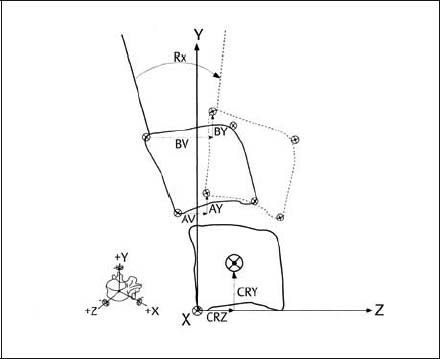
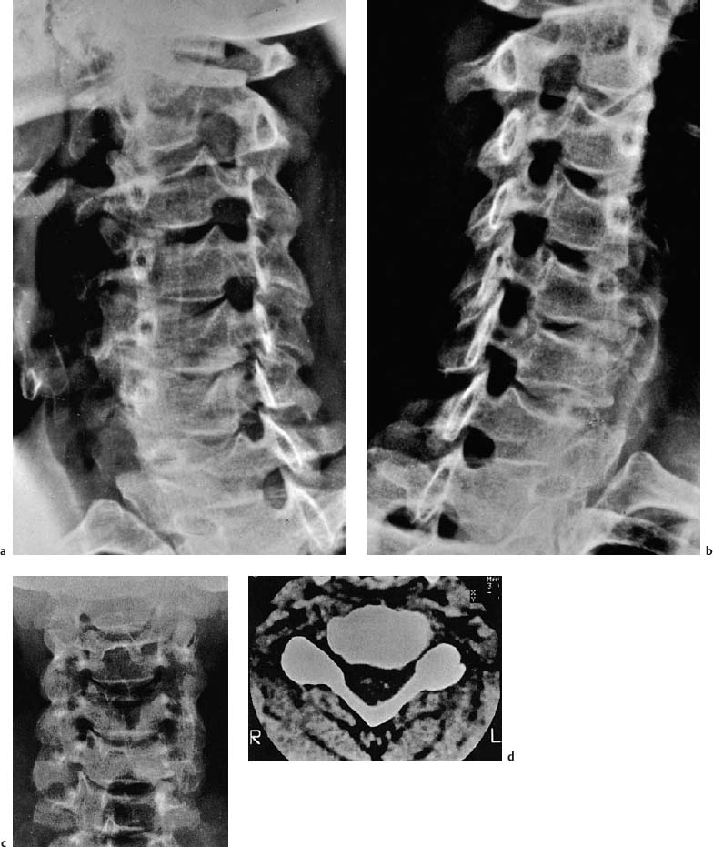
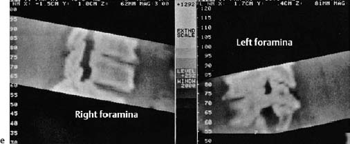
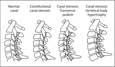
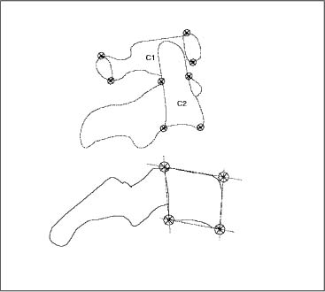
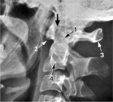
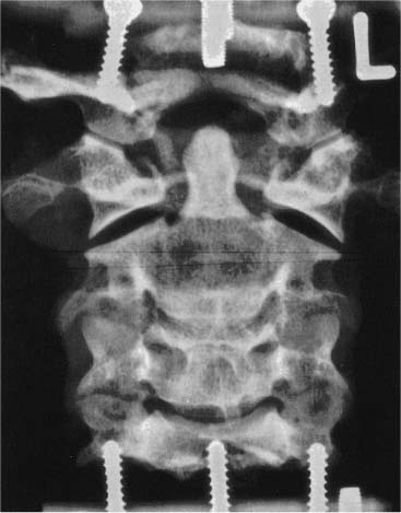
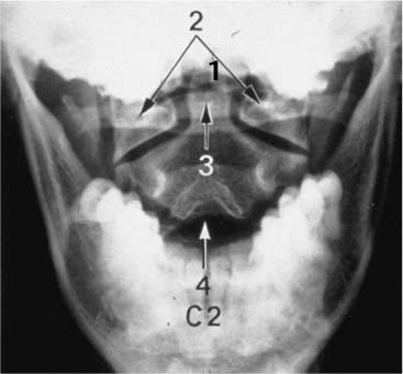
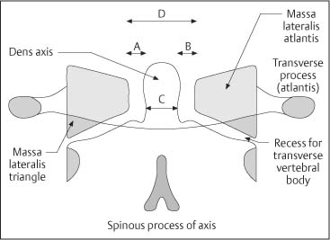
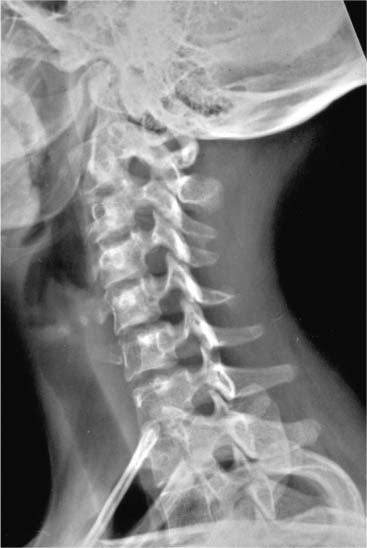
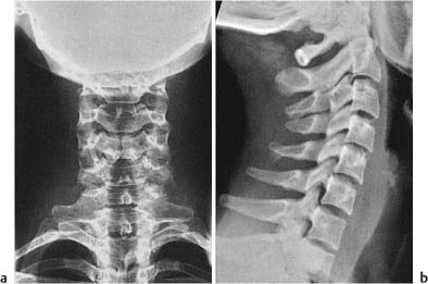
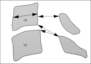
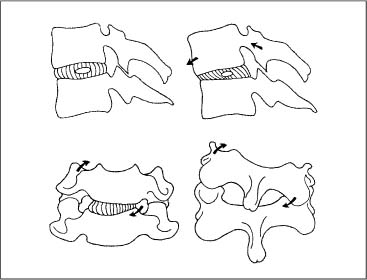
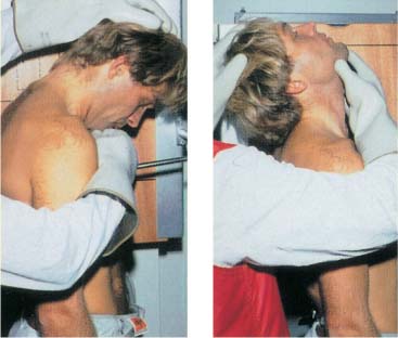
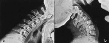
13 Imaging Studies of the Spine The ready availability of high-quality radiographs should not tempt the clinician to order them for every patient who presents to the office with neck or shoulder pain. Even though the exposure to roentgen rays has been significantly reduced in today’s studies, one should also keep in mind the cost–benefit ratio when ordering these studies. Previous research has shown that especially for non-malignant low back pain, routine radiographs of the spine are not indicated initially, that is during the first 4–6weeks of symptom presentation, especially when there is no indication of sinister pathology or specific co-morbidities. Scavone et al. (1981) examined the diagnostic value of 1000 lumbar spine radiographs, and showed that 75% of them did not provide any additional clinically useful information. Over half of the radiographs taken were normal; 30% were clinically questionable. Liang and Komaroff (1982) investigated the cost–benefit relationship between obtaining radiographs at the initial presentation and waiting 8 weeks. The study excluded patients with indications for a potential tumor, inflammatory disease, signs of disk herniation, or radiculopathy. It was concluded that the use of radiographic studies at the initial office visit is not justified in the absence of signs of sinister pathology. Simmons et al. (1995) provides the following literature review summary: “Standard radiographic studies of the lumbar spine are not indicated in patients who, in the absence of any signs of sinister pathology, present with low back pain that lasts less than seven weeks and who show gradual symptomatic improvement.” However, if the pain is thought to be due to structural/congenital abnormalities, fractures, inflammation, or malignant processes, then radiographic studies are clearly indicated as the next step in the clinical work-up routine. The history and clinical situations that help determine the need for plain radiographs include the following data: • Patient age—new onset of unexplained low back pain in a person older than 65 years. • High risk for osteoporosis (hormonal, corticosteroid use, oophorectomy history, etc.). • Known or suspected bladder or kidney disease. • Persistent neurologic sensory or motor deficits. • Progressive pain despite adequate treatment. • Intense pain even at rest. • Night pain. • Fever, chills, night sweats. • Unexplained weight loss. • Injury or trauma that may have resulted in a fracture. • History of repetitive stress loading to the spine that may have caused a stress fracture. • Changes in pain frequency, timing, duration or quality, intensity, and location. This should be done especially if previous studies were performed more than 2 years ago. • Previous low back surgery—to identify and evaluate postsurgical anatomy and hardware or whether there is a change in quality, intensity, duration, or type of the perceived pain. • History of other diagnostic studies such as a bone scan. • The need to prepare for further studies, such as an epidural injection. • The patient with an unreliable history. • Certain psychological or social circumstances. • History suspicious for cancer suspicion (primary or metastatic). • Decisions needed regarding the patient’s vocational fitness or future sports. • Potentially increased risk for injury during normal or routine functional or sports activities. • Specific legal considerations that need to be addressed. Based on their comprehensive review of the literature from 1966 to 2001, Jarvik and Deyo (2002) present two major conclusions about the diagnostic accuracy of clinical information and imaging for patients with low back pain in primary care settings: 1. For adults younger than 50 years with no signs or symptoms of systemic disease, symptomatic therapy without imaging is appropriate. 2. For patients 50 years of age and older or those whose findings suggest systemic disease, plain radiography and simple laboratory tests can almost completely rule out underlying systemic diseases. Advanced imaging should be reserved for patients who are considering surgery or those in whom systemic disease is strongly suspected. These recommendations are well founded on the current evidence. However, with regard to manual medicine, they do not take into account any specific consideration. Radiographic studies in manual medicine may be indicated if there are complaints of recurrent pain or if the practitioner is considering high-velocity low-amplitude thrust or articulatory techniques. The goal of such studies would be to determine as early as possible any potential instability or mechanical abnormality due to space-occupying lesions, fractures, inflammatory processes, or other pathologic states that would otherwise be contraindications for manipulation. In general, radiographs should not be ordered indiscriminately, simply as a “reflex” or as “something to do next,” or purely for medicolegal concerns. Haphazard use would certainly increase the chance of false-positive and false-negative results, not to speak of the unnecessary radiation exposure. Again, in situations where there is clinical uncertainty or suspicion of sinister disease, imaging studies are a logical next step. Such studies, when based on best clinical judgment and current evidence, will help in determining the next diagnostic steps and may provide reassurance to the individual patient that an occult diagnosis has not gone undetected. Standard radiographs of the cervical spine are used to determine major vertebral misalignment, segmental instability, fractures, and dislocations, and to quantify degenerative changes. Clues about the cervical soft tissues can also be obtained. This can be especially important in patients with rheumatoid arthritis, generalized osteoporosis, or previous surgery. The standard radiographs of the cervical spine include the anterior–posterior (AP) view, lateral views, and oblique views. If specific studies of the upper cervical spine or the craniocervical junction are indicated, they should include the AP views and the Sandberg–Gutmann views, in which the roentgen ray tube is tilted 20°. It must be noted that with all of these views there is radiation exposure and concern for the thyroid gland. A radiation shield can be employed without disrupting the diagnostic information in upper cervical spine studies. The following situations are indications for studies of the upper cervical spine: • Functional disturbance (e. g., somatic dysfunction) in the upper cervical spine based on the clinical examination. Findings may include pain elicited with palpatory examination, the presence of hypomobility and/or hypermobility, and pain that is reproduced by introducing rotation to the cervical spine while the head and neck are flexed. • Suspected congenital malformation. • Chronic polyarthritis affecting the cervical spine, e. g., rheumatoid arthritis. • History of recent injury or trauma and associated fracture of the cervical spine. Fig. 13.1 Lateral view of the upper cervical spine in a healthy person. 1 Dens of the axis 2 Anterior arch of the atlas 3 Posterior arch of atlas 4 Vertebral body of the axis The lateral view is performed at a distance of 1.5 m between the roentgen ray tube and the transverse process of the atlas (Fig. 13.1). In the AP view, it may be difficult to visualize the upper cervical spine (C0–C1). For example, the upper row of the teeth and the occipital bone may obliterate the upper cervical spine and thus render the study ineffective (Fig. 13.2). Zimmer (1937), Sandberg (1955), and Gutmann (1981) recommend that the upper cervical spine be radiographed with the head held in approximately 20° of extension while the roentgen ray beam is directed superiorly. This allows projection of the occipital shadow over the upper teeth, ensuring visualization of both sides of the articulations in the upper cervical spine. The disadvantage of this technique is the change in vertebral position in the upper cervical spine due to the head extension secondary to the coupled motion patterns in the upper cervical spinal joints. According to our own studies (Reich and Dvořák, 1986a,b), the “standard” transbuccal view may provide the best view. The transbuccal view attempts approximate the contour of the occiput and the upper row of the teeth. While the atlanto-occipital joint is not visualized in a detailed manner, this view reveals the dens of the axis, the lateral mass of the atlas, and the spinous process of the axis. For orientation, the upper row of the teeth and the transverse process of the atlas are utilized. The focus–film distance is 110 cm, which results in magnification by a factor from 1 to 1.25 (Reich, 1985). Fig. 13.2 AP view of the upper cervical spine in a prepared specimen, void of soft tissues. Presentation of the atlanto-occipital joint, the atlantoaxial joint, and the spinous processes of the second and third cervical vertebrae. Fig. 13.3 AP view of the upper cervical spine with identification of the salient structures. 1 Dens of the axis 2 Lateral mass of the atlas 3 Posterior arch of the atlas 4 Spinous process Fig. 13.4 Schematic representation of the bony structures used in the assessment of positional relationships between the atlas and the axis. This also allows measurement of the distance between the dens of the axis and the lateral mass of the atlas (A–B). These views serve as starting point for the functional lateral radiographs of the upper cervical spine (Fig. 13.3). Various authors recommend an evaluation of atlas position by looking for any asymmetries in the lateral mass triangle (LMT) (Lewit, 1964; Jirout, 1973; Kamieth 1983). The base of this triangle is formed by the posterior arch of the atlas. Any increase in distance is an indication of rotation toward one side. The distance between the lateral mass of the axis and the posterior arch of the atlas is a valuable sign that indicates rotation. The position of the axis is evaluated by comparing the position of the spinous process in relationship to the midline as well as asymmetry between the transverse process and the vertebral body from one side to the other (Kamieth, 1983) (Fig. 13.4). The symmetry between the body and the transverse process is a valuable criterion for axis rotation, especially since the spinous process is typically not located right at the center of the vertebra. The oblique view is utilized in the following situations: • Suspected narrowing of the intervertebral foramina. • Evaluation of the uncinate processes. • Status post trauma—unilateral or bilateral subluxation or overt dislocation. • Fractures of the articular processes. • Increase of the intervertebral foraminal space due to tumors such as neuroma or meningioma. The patient should stand for this technique. The body is rotated 45° with respect to the plane of the film. The left oblique view demonstrates the right intervertebral foramen and the right oblique view demonstrates the left intervertebral foramen. It may be good procedure to label the side of the foramen directly on the radiograph during the procedure to minimize error (Fig. 13.5). Figure 13.6a–e demonstrates a typical left-sided foraminal stenosis due to degenerative changes affecting the cervical spine. During the initial work-up of the mid-cervical and lower cervical spine, the AP and lateral views are the standard radiographic studies. The distance between the roentgen ray tube and the film is 1.5 m. The patient holds the head and neck in a neutral position, with the shoulders lowered maximally so that the cervicothoracic junction can be visualized. It is mandatory to count all the vertebral bodies to make sure that pathology is not missed (Penning, 1980), because the lower cervical spine may not be entirely visible, especially in muscular and obese patients. It may be necessary to utilize a 2–5-pound weight in each hand to lower the shoulders further, or to obtain the standard “swimmer’s view.” Normal lateral and AP views are demonstrated in Figure 13.7. The lateral view allows evaluation of the diameter of the spinal canal (Fig. 13.8) as well as the width of the retropharyngeal and retrotracheal space. The width of the retropharyngeal space is usually between 1 and 7 mm, while the retrotracheal space is 14 mm (Penning, 1980) (Fig. 13.9). The width of the spinal canal is determined by measuring the distance between the articular pillars and the lamina of the vertebral arch (Fig. 13.10). Fig. 13.5 Lateral view of the cervical spine of a 20-year-old woman with a cervical rib. The posture of the head and neck during the examination can have a notable effect on the curvature and appearance of cervical spinal lordosis. For instance, lowering of the patient’s shoulders during the radiographic procedure may introduce a reversal of the normal cervical lordosis simply due to natural adaptive postural changes. This is why it may not be meaningful to measure the degree of the cervical lordosis or kyphosis. Furthermore, such radiographic findings are reported as “abnormal,” but the actual clinical relevance of such a finding has not been fully determined. Fig. 13.6 a, b Lateral view of a 42-year-old man withleft-sided radicular symptomatology in the C6 sensory and motor distribution. There are symptoms associated with unisegmental foraminal spinal stenosis at C5–C6 due to posterior osteophyte formation and hypertrophy of the uncovertebral joints. c AP view. Note the sign of Guntz at C5–C6 left, which clearly reveals a new arthritic change. d Comparison examination using CT. e Reconstructed CT views comparing one right and left side. Fig. 13.7 Standard radiographs of the cervical spine. a A-P view. b Lateral view. Fig. 13.8 Schematic representation of the measurements for the width of the spinal canal. Fig. 13.9 Technique for measuring the retropharyngeal and retrotracheal space according to Penning (1980). Fig. 13.10 Schematic view of a different presentation of spinal canal stenosis in the cervical spine as represented in the lateral view. Constitutional canal stenosis secondary to hypoplasia of the laminae is the most frequent form. Canal stenoses due to transversely-oriented pedicles or due to vertebral body hypertrophy are relatively rare. (After Wackenheim and Dietemann, 1985a.) Fig. 13.11 Motion behavior in a final segment in relation to the facet (apophyseal joint) during flexion and extension motion as well as side-bending in rotation in the mid-cervical spine (Fielding, 1957). A significant number of patients who experience neck pain with movement, will not have objective evidence of an underlying structural abnormality. For this reason, functional radiographic studies have been employed. The goal is to determine whether the patient’s pain can be objectively correlated with segmental or regional motion limitations (e. g., hypomobility) or excesses (hypermobility). Bakke (1931) was the first to use radiographic studies to evaluate motion at the cervical spine. De Seze et al. (1951) and Buetti-Bäuml (1954) presented the first systematic functional radiographic results. A major contribution came from the American spinal surgeon JW Fielding, who introduced cineradiography to visualize normal and abnormal cervical spinal motion (Fielding, 1957). His clear depiction and graphic representations of the relationship between the cervical intervertebral disks and the apophyseal joints during flexion, extension, and side-bending as well as rotation have as much validity today as they did when they were initially presented (Fielding, 1957) (Fig. 13.11). The pioneering work by the Dutch radiologist, Lourens Penning was a major contribution to the understanding of the functional pathology of the cervical spine. His dissertation was a treatise about the degenerative process and its etiology of the uncovertebral joints in the cervical spine (Penning, 1960). This was followed by his seminal study in 1963 on the normal and abnormal ranges of motion in the cervical spine (Penning and Töndury, 1963). Technological advances have resulted in the use of CT scans and magnetic imaging to study motion of the cervical spine. In the past, technical difficulties (projections that were unable to visualize the upper cervical spinal joints) stood in the way of detailed analysis. Newer technologies have allowed further study, especially that of axial rotation (Dvořák and Panjabi, 1987b; Dvořák et al., 1987a, c; Ono et al., 1984; Penning and Wilmink, 1987a,b). Based on our own studies (Dvořák et al., 1988d) and Fröhlich (1988), there is a significant difference between active and passive motion at all spinal levels in flexion and extension. Passive radiographic examination provides the most relevant and reliable information. One of the limiting factors is the pain that would typically appear at the extreme of motion. This may be due to muscle spasm and is quite often reported in the radiological reports associated with a “straightening of the curve.” However, more importantly, the pain may actually be due to segmental instability. Thus it is helpful to encourage the patient to relax as much as possible during the examination. Even with such preparation, the passive functional radiographic study may not provide much additional information in a patient with advanced degenerative changes in the presence of segmental hypomobility. The contraindications for passive flexion and extension motion studies include a history of recent cervical spine trauma, chronic polyarthritis, as well as suspected primary space-occupying lesions or metastases. The study is performed with the patient standing and the left side of the body placed against the film plate. The distance between the film and the roentgen ray tube is 1.5 m. The focus of the beam is upon the mid cervical spine. The patient should be as relaxed as possible, with the shoulders lowered maximally. The patient is stabilized between two padded supports placed anterior to the sternum and posterior to the mid thoracic spine. This helps facilitate a neutral patient position. One should be careful not to introduce rotation, in order to maintain clear visualization of the vertebral bodies. Initially, the patient is instructed to carefully nod his or her head, which introduces a nutation motion (flexion) at C0–C1 and C1–C2. From this flexed position, further flexion is introduced to the neck until the maximal allowable flexion position is reached by the patient. In this final, actively engaged position, the first radiograph is taken. For the passive examination, the radiologist wears a lead apron, lead gloves, and lead glasses. The left hand of the radiologist is placed over the posterior portion of the patient’s head and the parietal region, while the right hand is placed over the patient’s chin. After introducing maximal passive inclination (flexion) at C0–C1 and C1–C2, the operator introduces maximal passive flexion to the remainder of the cervical spine. In this position, the second radiograph is taken. Once the flexed radiograph has been taken, the head is guided passively into maximal reclination (that is, extension motion) at C0–C1 and C1–C2, followed by maximal allowable extension introduced to the neck by the radiologist’s guiding hand. Every care should be taken that the hand guides the head and neck into these positions in a slow, careful, and precise manner (Fig. 13.12). If pain is elicited or exacerbated during the functional examination, it may be necessary to reschedule the patient. In our experience, low-dose analgesic or nonsteroidal anti-inflammatory may help facilitate the execution of the study. Again, it is emphasized that if there is pain associated with the passive maneuver, consideration should be given to the potential presence of segmental instability. If the patient reports the onset of dizziness, nausea, or other autonomic symptoms, further diagnostic neurologic evaluation may be warranted. Representative flexion and extension views utilizing the functional radiographic examination protocol just described are shown in Fig. 13.13. The original method presented by Penning (1960) has been found to be the most useful and reliable method, as well as the computer-assisted method presented by Dvořák et al. (1988d). The techniques introduced by Bakke (1931), De Seze (1951), Buetti-Bäuml (1954) have not been able to reproduce data sufficiently consistently (Fröhlich, 1988; Dvořák et al., 1988d). The two current procedures used to measure passive segmental and regional range of motion in the cervical spine are the graphic method and the computer-assisted method. They are described as follows. Fig. 13.12 Examination technique for passive flexion and extension views using functional radiographic diagnosis in the cervical spine (Dvořák et al., 1988d; Frohlich, 1988). Fig. 13.13 Passive (a) flexion and (b) extension views during functional examination. The cervicothoracic junction should be viewable, requiring that the patient lower the shoulders as much as possible. This method was originally described by Penning in 1960. The flexion view is projected onto the normal film of 24 × 36 cm size and the extension view onto one of 18 × 24 cm. The radiographic film of the extension view is placed upon that of the flexion view while the spinous processes and the vertebral bodies of C7 are matched as much as possible. Subsequently, a line is drawn following the edge of the seventh cervical vertebra in the extension view and the flexion view. This procedure will then be repeated for each vertebra superior to C7. The angle created between the two lines thus marked on the films in the maximal flexion and extension position will determine the degree of range of motion between maximal passive flexion and extension. Fig. 13.14 Landmarks for the computer-assisted method used to determine segmental motion. The landmark of the axis is somewhat difficult because the osseous structures cannot always be clearly defined. Fig. 13.15 Labeling of the different reference points used in the calculations using a computer-assisted model (CAM).
Introductory Remarks
Cervical Spine
Plain Radiographs
Upper Cervical Spine: AP and Lateral Views
Cervical Spine: Oblique View
Mid and Lower Cervical Spine: AP and Lateral Views

Functional Radiographic Studies of the Cervical Spine
Functional Radiographic Diagnosis of the Cervical Spine: Flexion and Extension
The Graphic Method