Imaging of the Knee
Charles P. Ho
Comprehensive examination of the symptomatic knee frequently may require diagnostic imaging to complement and supplement the physical examination for full diagnosis and prognosis of injury. The many derangements may present as overlapping pain syndromes, for which imaging information may provide clarification. Even with specific known injury, detailed imaging may be invaluable for treatment planning and monitoring. The many imaging techniques now available may be selected to address bone and soft tissue injury, for screening and for more specific evaluation.
Radiographic Imaging
Conventional radiography is the most widely available and used imaging modality for the orthopaedic patient. Based on the tissue properties for attenuation of x-ray beams projected through the patient’s knee and then sensed by appropriate film or other detectors for display, radiographs reveal details and contrast for high-attenuation materials such as bone, calcification, and metallic foreign bodies or hardware. Soft tissues have much lower and less variable attenuation properties and therefore much less radiographic contrast for delineation and evaluation of their structures.
Thus, radiographs are excellent for evaluation of the symptomatic knee for osseous fracture and reaction and for metallic implants. Radiographs assist in evaluation of the mechanical axis and alignment of bone and joints, including in the weightbearing stance. The screening radiograph also aids in finding the unexpected underlying process, such as tumor and other destructive lesions, or for metallic foreign bodies.
However, radiographs have limited value when soft tissue injury is the concern of the patient and treating physician. The utility of radiographs for evaluation of internal derangement of the knee is limited beyond screening for large effusions and for nonspecific soft tissue swelling. Purely soft tissue damage to menisci, chondral surfaces, ligaments, and tendons may not be apparent on radiographs. Milder osseous injury from contusion to impaction or avulsion fractures with little or no displacement may be difficult to see on radiographs. Radiographic findings of joint-space narrowing, sclerosis, osseous remodeling, marginal and central osteophytes, subchondral and subcortical cysts, and heterotopic bone formation are all late reactive changes, sequelae to severe chronic joint internal derangement, and soft tissue injury.
Magnetic Resonance Imaging
The advent of magnetic resonance imaging (MRI) has been truly revolutionary for diagnostic imaging, including orthopaedic imaging. By using radiofrequency waves to stimulate mobile protons, specifically hydrogen nuclei, in body tissues and then detecting the signals given off by those
protons when they return to the nonexcited state, all under the influence of a high magnetic field to increase the strength of weak signals, MRI systems can then construct high-resolution images of those tissues and structures being imaged.
protons when they return to the nonexcited state, all under the influence of a high magnetic field to increase the strength of weak signals, MRI systems can then construct high-resolution images of those tissues and structures being imaged.
The overwhelming strengths of MRI lie in the areas that are limitations that we find in radiographic imaging. The abundant hydrogen nuclei in the varying tissue environments of the musculoskeletal system provide excellent signal and contrast for superb imaging of the soft tissues as well as the osseous structures about the knee. MRI also has volume and multiplanar tomographic capability that can be optimized for imaging, as various portions of complex three-dimensional structures (including those of the knee) are best evaluated in each of the three standard orthogonal planes. Customized planes of imaging, although not generally needed, can also be tailored to specific structures when warranted.
These structures have specific normal morphologic and signal characteristics and can be evaluated for derangement of both. In more acute injuries, edema, inflammation, and hemorrhage disturb the tissue’s normal signal and present as increased signal within and about the injured structures on fluid-sensitive T2-weighted MRI sequences. These are particularly conspicuous when the background high signal of marrow fat and soft tissue fat planes are eliminated by fat-suppression MRI techniques. With chronic injuries, the benefit of an increased signal indicating edema or inflammation may no longer be present, but disturbances of morphology generally are still present to be evaluated. Thus, meniscal tears, chondral defects, and ligament and tendon tears that are not apparent on radiographs are accurately evaluated by MRI.1 2 3 4 5 6 7 Bone contusions and stress reactions and even fractures,8 particularly when incomplete or with little or no displacement, may not be visible on radiographs, but are also sensitively apparent on MRIs as increased
signal edema and hemorrhage within the bone and the surrounding soft tissues. The accurate evaluation by MRI of soft tissue and bone injury can assist the treating physician in planning management.
signal edema and hemorrhage within the bone and the surrounding soft tissues. The accurate evaluation by MRI of soft tissue and bone injury can assist the treating physician in planning management.
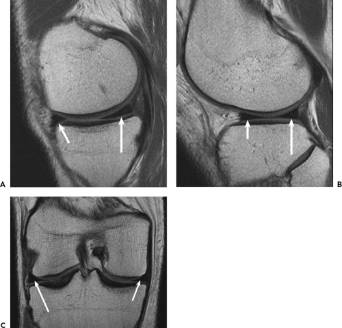 Figure 7.1. Normal magnetic resonance imaging appearance of medial and lateral menisci. Menisci should have low signal with smooth margins and a triangular cross section on sagittal and coronal images. A: Sagittal proton density image through the medial compartment shows normal smaller anterior (short arrow) and larger posterior (long arrow) horns of medial meniscus. B: Sagittal proton density image through lateral compartment demonstrates normal anterior (short arrow) and posterior (long arrow) horns, of nearly equal size, of the lateral meniscus. C: Coronal proton density image shows normal medial (short arrow) and lateral (long arrow) menisci at the mid meniscal body portions. |
Limitations of current MRI techniques must also be considered. MRI may not be able to resolve small fracture lines or fragments or small areas of calcification, which are often still better detected and evaluated by radiologists or other examiners on conventional radiographs and particularly on computed tomography (CT) scans. Also, while MRI is sensitive and excellent for detecting and staging unexpected, as well as clinically apparent osseous and soft tissue masses, the MRI characteristics of such masses may not be specific. Evaluation and correlation for such masses can be much more specific on radiographs. Often radiographs may be needed in addition to the MRI.
Meniscus Imaging
One of the initial applications of MRI to the musculoskeletal system was in evaluation of the knee meniscus.9 Both medial and lateral menisci are best evaluated using both sagittal and coronal plane images, such that the various portions of the menisci can be studied in cross section from the central free edge to the peripheral margins and synovial junction. The normal meniscus has well-defined smooth margins and, with few mobile protons in the fibrocartilage to generate signal, low or no signal on all MRI sequences (Fig. 7.1).
With repetitive stress and aging contributing to degeneration of the meniscus, the margins may become irregular, with roughening and fraying. Intrasubstance degeneration manifests as an increased signal within the meniscus.9 It may begin as a poorly defined increased signal within the more peripheral meniscal tissue, possibly extending to the meniscosynovial junction. The degeneration may progress to coalesce as intrasubstance cleavage planes or “closed tears,” presenting as more prominent and discrete, usually horizontal, longitudinal linear increased intrameniscal signals. When these cleavage planes and the corresponding MRI high signal reach and disrupt the meniscal articular margins, the characteristic degenerative horizontal longitudinal cleavage tear may be seen.
With traumatic meniscal injury, tears of even otherwise normal low-signal meniscal tissue are seen as disruptions of the normal margins and position, with possible displacement of the meniscus tissue in other more discrete tear patterns such as focal free-edge tears to radial tears, vertical-to-oblique longitudinal flap tears, and bucket-handle tears (Fig. 7.2 Fig. 7.3 Fig. 7.4). The meniscosynovial junction may also be disrupted with separation and displacement of the detached or stripped meniscus. The tear location and morphology as well as displaced fragments or flaps can be accurately evaluated by a radiologist on the sagittal and coronal MR images,10,11 often usefully supplemented by the axial images particularly for displaced fragments or flaps. The accurate MRI evaluation and report can be extremely helpful to the treating physician for prognosis and treatment planning, assisting in finding potentially unstable meniscal lesions, and can serve as an intraoperative roadmap to detect displaced fragments that may be trapped and not readily visible by standard arthroscopic views.
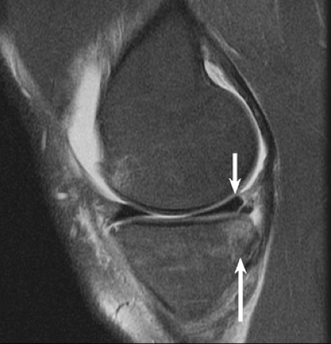 Figure 7.2. Vertical longitudinal tear demonstrated as a high signal line disrupting peripheral superior and inferior margins of the medial meniscus posterior horn (short arrow) on a sagittal fat-suppressed proton density image through the medial compartment. Note the geographic bone edema and contusion of the underlying posterior medial tibial plateau (long arrow) shown as abnormal high bone signal on fat-suppression image. |
Understanding the injury mechanism and pattern can be helpful in accurate evaluation of the imaging examination, as well as in the clinical examination. Characteristic mensical tear patterns may be seen in specific injury patterns. For example, with tears of the anterior cruciate ligament (ACL) involving internal rotation valgus forces and corresponding pivot-shift, oblique longitudinal tears and flap tears of the lateral meniscus posterior horn extending toward the notch as well as often oblique radial tears of the lateral meniscus at junction of body and anterior horn portions are commonly seen, likely corresponding to the areas of impaction force of the anterior lateral femoral condyle against the posterior lateral tibial plateau in the forced pivot-shift and rebound (Fig. 7.4). Peripheral vertical longitudinal and meniscosynovial junction tears of the medial meniscus posterior horn to body are also commonly encountered. These tears are likely associated with the contusion and impaction injury of the posterior medial tibial plateau often associated with ACL tears (Fig. 7.2).
Articular Cartilage and Bone Imaging
MRI has enabled accurate imaging evaluation of articular cartilage damage that could previously only be inferred in
severe chronic settings by late radiographic osseous and joint-space changes. Soft tissue contrast and multiplanar imaging strengths of MRI are particularly well suited for assessment of the complex curved articular surfaces of the knee, including such areas as the femoral trochlea that can be treacherous to both clinical and imaging diagnosis. Detection of earlier stages of degenerative as well as traumatic changes, is now feasible, and may enable earlier treatment that could potentially slow or even arrest progression to late or end-stage sequelae.
severe chronic settings by late radiographic osseous and joint-space changes. Soft tissue contrast and multiplanar imaging strengths of MRI are particularly well suited for assessment of the complex curved articular surfaces of the knee, including such areas as the femoral trochlea that can be treacherous to both clinical and imaging diagnosis. Detection of earlier stages of degenerative as well as traumatic changes, is now feasible, and may enable earlier treatment that could potentially slow or even arrest progression to late or end-stage sequelae.
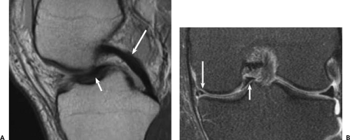 Figure 7.3. Bucket-handle tear of medial meniscus displaced into intercondylar notch. A: Sagittal proton density image through the notch shows displaced bucket-handle meniscal tissue (short arrow) within notch anterior and inferior to the posterior cruciate ligament (long arrow). B: Coronal fat-suppressed proton density image confirms the meniscal bucket-handle (short arrow) displaced into notch away from the peripheral remnant of the medial meniscus body (long arrow). |
MRI enables noninvasive direct imaging of morphologic changes such as chondral fibrillation, fissuring, focal defects and corresponding fragments, and more diffuse thinning and wear, all manifesting as changes of the chondral thickness and surface at the cartilage interface to joint fluid and synovium. Earlier chondral degenerative changes, such as softening or blistering, to later fibrotic change can also be visible as intrasubstance areas of MRI signal change and inhomogeneity, although such evaluation is still qualitative in standard clinical practice.
Chondral Imaging Technique
As with other applications in clinical musculoskeletal MRI, numerous types of MRI sequences are available for and have been applied to chondral imaging.12 13 14 15 16 17 18 The clinical results and experience have been quite varied, and the choice of imaging protocol may be particularly important for evaluation of articular cartilage. The MRI appearance of articular cartilage varies considerably with the type of sequence applied. Specialized “cartilage-specific” sequences have been used, generally based on various gradient echo techniques that usually result in chondral signal that is relatively high or bright compared with subchondral bone and overlying joint fluid and synovium. The high contrast between the bright cartilage and dark underlying bone delineates well the cartilage-to-bone interface, but the lower contrast with the overlying higher signal fluid and synovium demonstrates more poorly the cartilage surface and interface to the fluid. Small, more focal chondral fissures or flaps may be difficult to appreciate as small areas of lower signal in a background of bright cartilage. Sensitivity to partial or even full-thickness chondral thinning to focal defects may also be poor. Also, the gradient echo techniques tend to have poor contrast differentiation and resulting limited sensitivity for evaluation of the subchondral bone as well as the remainder of the soft tissues about the knee.
Spin echo or turbo/fast spin echo sequences have also been used, generally producing a cartilage signal that is low compared with the overlying fluid and synovium. The high contrast demonstrates the chondral surface interface well. Fibrillation, fissures, flaps, and defects are easily seen as focal high-signal and high-contrast changes in a low-signal chondral background. The low cartilage signal on spin echo sequences provides less contrast for evaluation of the cartilage interface to the low or absent signal of the underlying bone plate. This interface is also further obscured by a chemical shift artifact between the fat signal of the underlying bone marrow and the water signal of cartilage. However, fat-suppression techniques may be added to eliminate the chemical shift artifact, as well as to suppress the image high background signal of marrow fat and soft tissue fat planes. This suppression of fat signal expands and magnifies the dynamic range of display of the remaining chondral and other soft tissue and bone signals for better sensitivity
and visibility of the cartilage-to-bone interface, as well as the cartilage substance and surface/interface to overlying fluid and synovium. Injury and resulting signal changes of bone and of soft tissue structures about the knee may also be better demonstrated.
and visibility of the cartilage-to-bone interface, as well as the cartilage substance and surface/interface to overlying fluid and synovium. Injury and resulting signal changes of bone and of soft tissue structures about the knee may also be better demonstrated.
 Figure 7.4. Lateral meniscus anterior and posterior horn tears. A: Sagittal fat-suppressed proton density image reveals radial tear of the meniscus at junction of anterior horn and body portions (short arrow), and segmental defect tear of the posterior horn along and posterior to the popliteus hiatus (long arrow). Note the associated bone high-signal edema of contusion and mild impaction injuries of the anterior lateral femoral condyle and posterior lateral tibial condyle/plateau (curved arrows) in this patient with acute tear of the anterior cruciate ligament (not shown on these images). B: Axial proton density image further confirms the extent of the radial (short arrow) and segmental defect (long arrow) tears of the lateral meniscus of the same patient as in Figure 7.4A. C: Sagittal fat-suppressed proton density image of a different patient with acute tear of the anterior cruciate ligament identifies peripheral vertical longitudinal tear of the lateral meniscus posterior horn (straight arrow) along the popliteus hiatus. Note also the bone high-signal edema and contusions of the anterior lateral femoral condyle and posterior lateral tibial condyle/plateau (curved arrows). |
Clinical Practice of Chondral and Bone Imaging
Spin echo and turbo/fast spin echo techniques, without and with fat suppression, remain the mainstay of MRI, and have proven accurate in evaluation of chondral as well as other soft tissue and bone derangement. A standard imaging protocol employing these sequences can then provide a comprehensive knee examination for essentially all clinical indications. Images should be obtained in all three orthogonal planes about the knee, as the planes are all complementary and each plane is best suited for evaluation of specific portions of the complex three-dimensional structures including chondral surfaces of the knee.
Articular cartilage is often and easily overlooked in imaging examinations. Perhaps more than for any other part of the knee, the chondral surfaces should be evaluated consciously and specifically in each imaging sequence and examination. The tibial plateaus and femoral condyles are well delineated on sagittal and coronal images. The patella and particularly the complex curved trochlea surfaces should be evaluated fully by combining sagittal and axial images.
Chondral fibrillation, fissures, and flaps should be evaluated and described precisely (Fig. 7.5 and Fig. 7.6). Acute
chondral defects should be differentiated from chronic grade 4 chondral loss, as treatment and prognosis may be quite different. More focal sharply marginated defects may indicate more acute injury and the corresponding fragments should be found and reported (Fig. 7.7). The subchondral bone should also be evaluated for more acute contusion or impaction injury with resulting high-signal edema, best seen on fat-suppressed images and often seen in conjunction with the more acute chondral injury. More diffuse chondral thinning may indicate chronic degenerative wear, possibly from remote trauma,19 which should be evaluated and reported (Fig. 7.8). More chronic reactive osteitis of the subchondral bone may be seen as relatively increased signal, typically in combination with other chronic osseous changes of sclerosis, remodeling, cystic change, and osteophyte formation. In practice, the subchondral bone changes when identified in both acute and chronic settings are important and extremely helpful indicators of likely overlying chondral changes. For example, the forces producing acute contusion or an impaction fracture injury of the subchondral bone must be transmitted through and also will likely cause injury to the overlying articular cartilage.20 The cartilage should then be specifically examined to find or exclude the anticipated corresponding chondral derangement (Fig. 7.5).
chondral defects should be differentiated from chronic grade 4 chondral loss, as treatment and prognosis may be quite different. More focal sharply marginated defects may indicate more acute injury and the corresponding fragments should be found and reported (Fig. 7.7). The subchondral bone should also be evaluated for more acute contusion or impaction injury with resulting high-signal edema, best seen on fat-suppressed images and often seen in conjunction with the more acute chondral injury. More diffuse chondral thinning may indicate chronic degenerative wear, possibly from remote trauma,19 which should be evaluated and reported (Fig. 7.8). More chronic reactive osteitis of the subchondral bone may be seen as relatively increased signal, typically in combination with other chronic osseous changes of sclerosis, remodeling, cystic change, and osteophyte formation. In practice, the subchondral bone changes when identified in both acute and chronic settings are important and extremely helpful indicators of likely overlying chondral changes. For example, the forces producing acute contusion or an impaction fracture injury of the subchondral bone must be transmitted through and also will likely cause injury to the overlying articular cartilage.20 The cartilage should then be specifically examined to find or exclude the anticipated corresponding chondral derangement (Fig. 7.5).
 Figure 7.5. Focal chondral fracture of the lateral tibial plateau. A: Coronal fat-suppressed proton density image demonstrates bone high signal edema of contusion/impaction injury of the lateral tibal plateau (long arrow) with high-signal fluid in the focal fracture (short arrow) of the overlying articular cartilage. B: Axial fat-suppressed proton density image confirms the high signal focal chondral fracture (arrow) of the lateral tibial plateau. |
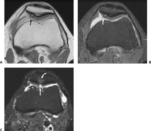 Figure 7.6. Patellar chondral focal fissuring and fracture to bone. A: Axial proton density image shows the chondral fraying and more focal high signal fissure (arrow) to bone over the medial facet of the patella. B: Axial fat-suppressed proton density image at the same level shows more conspicuously the high-signal focal fissure (arrow) to bone over the medial facet. C: Axial fat-suppressed proton density image of a different patient reveals high signal fluid in a focal sharply marginated chondral fracture (straight arrow) to bone on the patella median ridge with poorly defined high signal edema of contusion of the underlying bone (curved arrow). |
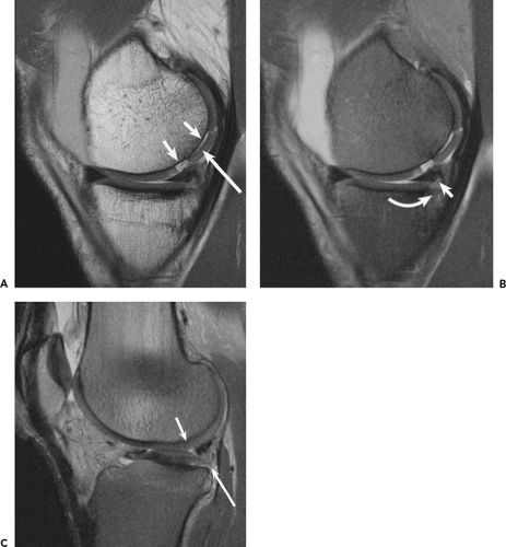 Figure 7.7. Chondral defect and fragment of medial femoral condyle, and chondral flap of lateral tibial plateau. A: Sagittal proton density image reveals focal chondral defect (short arrows) of posterior weightbearing aspect of medial femoral condyle, with corresponding crescentic chondral fragment (long arrow) partially displaced within the defect. The sharp margins of defect and fragment indicate an acute injury. B: Sagittal fat-suppressed proton density image at the same level demonstrates more conspicuously the high-signal fluid within the defect and outlining the fragment, as well as the peripheral inferior surface tear of the medial meniscus posterior horn (straight arrow) and the underlying chondral fissuring and bone edema (curved arrow) of the posterior margin of the medial tibial plateau. C: Sagittal fat-suppressed proton density image of the lateral compartment shows chondral undermining and flap (long arrow). Note also the corresponding small radial free edge tear of the overlying lateral meniscus posterior horn (short arrow). The posterior lateral injury forces have damaged both of these soft tissue structures. |
With acute bone injury, the high-signal intraosseous edema and hemorrhage are conspicuously seen on fat-suppressed images. MRI is exceedingly sensitive for identifying acute bone injury21 (Fig. 7.9). However, fracture lines or avulsion fragments may be difficult to identify, particularly
when they are incomplete or when little or no displacement is present. Correlation with radiographic imaging may assist in evaluation. CT examinations particularly can assist in detecting more discrete fracture lines, fragments, and alignment, and should be considered when such additional information may influence treatment. MRI is also sensitive for repetitive stress or overuse injuries of bone in athletes,8 from stress reactions with poorly defined bone edema to more discrete stress or insufficiency trabecular fracture lines (Fig. 7.10). However, again, the more focal cortical fracture lines may be difficult to see on MRI. CT correlation may be helpful when warranted for treatment decisions.
when they are incomplete or when little or no displacement is present. Correlation with radiographic imaging may assist in evaluation. CT examinations particularly can assist in detecting more discrete fracture lines, fragments, and alignment, and should be considered when such additional information may influence treatment. MRI is also sensitive for repetitive stress or overuse injuries of bone in athletes,8 from stress reactions with poorly defined bone edema to more discrete stress or insufficiency trabecular fracture lines (Fig. 7.10). However, again, the more focal cortical fracture lines may be difficult to see on MRI. CT correlation may be helpful when warranted for treatment decisions.
 Figure 7.8. Grade 4 chondral thinning to bone of the medial tibial plateau (arrows) greater than to adjacent medial femoral condyle. The diffuse extensive chondral absence with subchondral bone low-signal sclerosis and flattening and remodeling correspond with more chronic degenerative chondral loss. A: Sagittal proton density image. B: Coronal proton density image. |
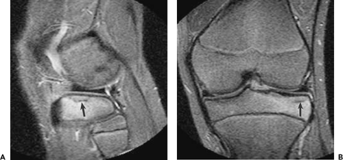 Figure 7.9. Impaction fracture football injury of the lateral tibial plateau with little or no displacement in 11-year-old boy. The high-signal, poorly defined bone edema of the contusion/impaction injury outlines conspicuously the more focal linear low-signal fracture line (arrow). A: Sagittal fat-suppressed proton density image. B: Coronal fat-suppressed proton density image. |
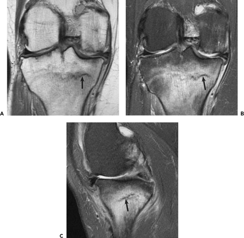 Figure 7.10. Insufficiency stress fracture of proximal medial tibia in a 57-year-old woman. The incomplete low-signal fracture line (arrow) is outlined by prominent, poorly defined bone edema that has intermediate signal on the proton density image and a more conspicuous high signal on fat-suppressed proton density image in which the previously high background signal of fatty marrow has been suppressed, leaving the now more conspicuous high signal of bone edema. A: Coronal proton density image. B: Coronal fat-suppressed proton density image at the same level. C: Sagittal fat-suppressed proton density image. |
MRI may assist in selecting chondral resurfacing treatment and evaluating response to treatment and evolution of chondral resurfacing.22 23 24 25 26 27 More focal and likely acute chondral defects may be better candidates with better prognosis for resurfacing (Fig. 7.7). A patient with more chronic diffuse chondral thinning to bone with chronic subchondral sclerosis or eburnation and cystic change may be a less likely candidate with poorer prognosis (Fig. 7.8). With microfracture or autologous chondrocyte implantation,28 29 30 31 32 33 34 35 the filling and maturation of new cartilaginous material in treated chondral defects can be monitored (Fig. 7.11 Fig. 7.12 Fig. 7.13). Perhaps more importantly, when clinical course is not meeting expectations, poor filling or early and abortive breakdown of new material in the treated defect can be identified by reading the MRI examination. With osteochondral autograft or allograft treatment,36 the incorporation and healing of the graft to surrounding native bone and cartilage may be evaluated (Fig. 7.14). Graft alignment, including potential problems of angulation or step-off of the graft from depression or elevation relative to the surrounding native articular surface, may be evaluated on the MRI (Fig 7.15).
Related posts:
 The ACL-Deficient Knee: Some Thoughts—Past and Future
The Healing Response Technique: A Minimally Invasive Procedure to Stimulate Healing of Anterior Cruciate Ligament Injuries Using the Microfracture Technique
A Look Beyond the Horizon
Functional Biomechanics of Healthy, Anterior Cruciate Ligament-Deficient and -Reconstructed Knees
Microfracture
The ACL-Deficient Knee: Some Thoughts—Past and Future
The ACL-Deficient Knee: Some Thoughts—Past and Future
The Healing Response Technique: A Minimally Invasive Procedure to Stimulate Healing of Anterior Cruciate Ligament Injuries Using the Microfracture Technique
A Look Beyond the Horizon
Functional Biomechanics of Healthy, Anterior Cruciate Ligament-Deficient and -Reconstructed Knees
Microfracture
Stay updated, free articles. Join our Telegram channel

Full access? Get Clinical Tree


